


Concept Laser’s QMmeltpool 3D: In-situ quality assurance with real-time monitoring down to the micron level
Concept Laser, based in Lichtenfels, Germany, is a leading provider of manufacturing equipment for metal Additive Manufacturing using its patented LaserCUSING® technology. In this article, the company reports on the development of the next generation of its quality assurance monitoring system, QMmeltpool 3D, which will be available on its M1 and M2 cusing machines from 2016. The system, states Concept Laser, promises to make a significant contribution to detecting process defects at an early stage as well as being an indispensable tool for process optimisation. [First published in Metal AM Vol. 1 No. 2, Summer 2015 | 10 minute read | View on Issuu | Download PDF]
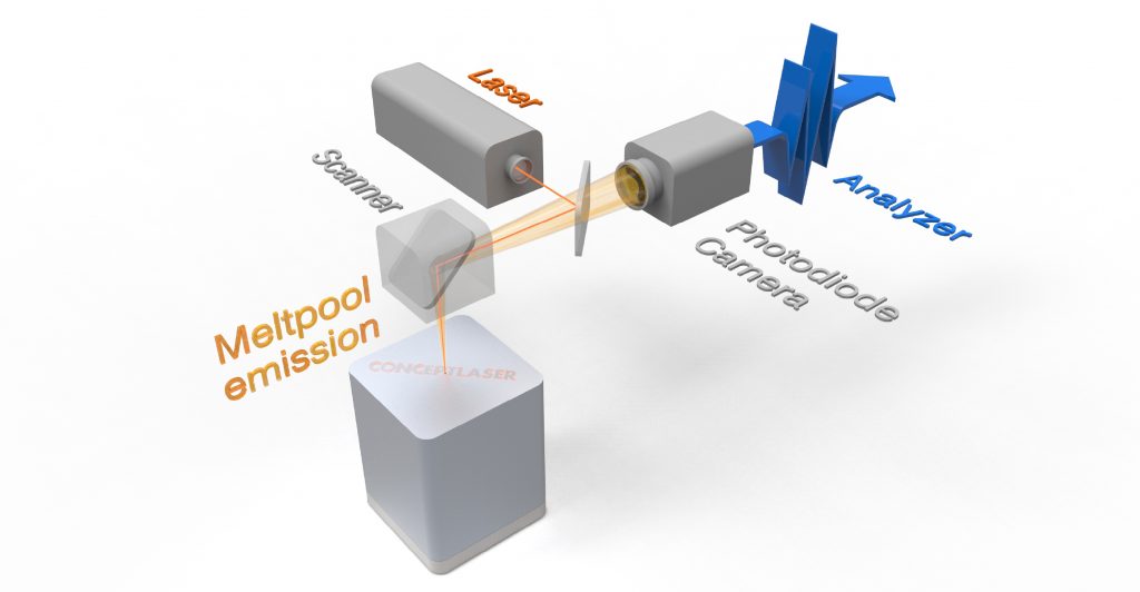
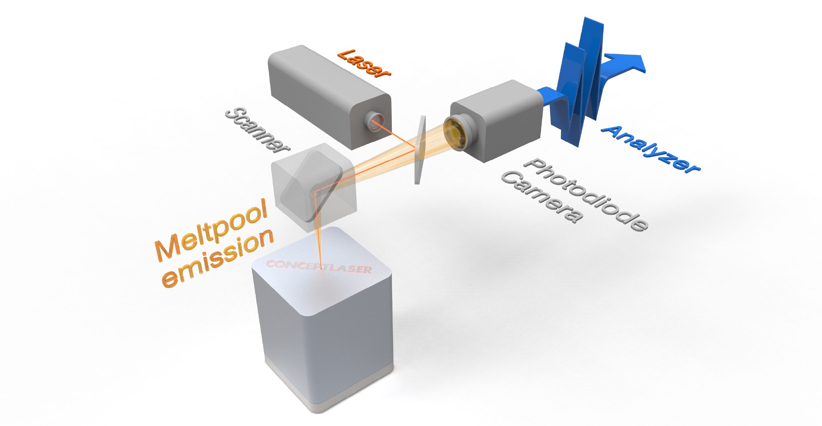
Active quality assurance is one of the most important requirements for producers of critical components by metal Additive Manufacturing and monitoring the key data of a laser melting system, such as oxygen content, temperature, laser output and powder quality, is now commonplace during production. A comprehensive statement regarding the quality of a part cannot, however, simply be made on the basis of machine parameters. With in-situ process monitoring systems based on an on-axis system, it is now possible to obtain information about defects during the build process. Concept Laser has announced the development of a system for position-related, real-time monitoring and three-dimensional visualisation for its LaserCUSING® process. The system, QMmeltpool 3D (Fig. 1), will be available from 2016 onwards for the company’s M1 cusing and M2 cusing machines and offers users the next generation of quality assurance tools.

Sources of defects during laser melting
In challenging application sectors such as medical, automotive and aerospace, safety requirements are strict and high quality is a prerequisite. Defects that can occur during laser melting are as the result of an extremely wide range of influencing factors. Examples include scanning speed or laser output. Process defects can, for instance, be caused by scanning speeds that are either too low or too high, having the effect of excessive or inadequate energy input. Inadequate energy input into the powder bed can lead to unmelted powder in the form of irregularly shaped pores. If the energy input is too high, on the other hand, gas inclusions can be formed that are revealed in micrographs as regular, round pores. The process gas flow, the material and many other factors can also influence the process and part quality.
QMmeltpool 3D generates quality-relevant data in real time for process monitoring and documentation. The system records position-related characteristics of the melt pool while the component is being built. This data can be visualised in a three-dimensional landscape and analysed by the user. Concept Laser states that the quality of the visualisation is comparable to the HD resolution achieved by Computer Tomography (CT).
Process monitoring in laser melting technologies
The QMmeltpool system uses coaxial sensors to detect melt pool emissions that are created during the fusing process in the form of infrared radiation. The coaxial structure allows restriction to a small region of interest with a high local resolution and rapid scanning rates of up to 50 kHz, depending on the detector type. This melt pool monitoring identifies two characteristic parameters; the melt pool area and melt pool intensity. These characteristic parameters can be allocated to corresponding process errors.

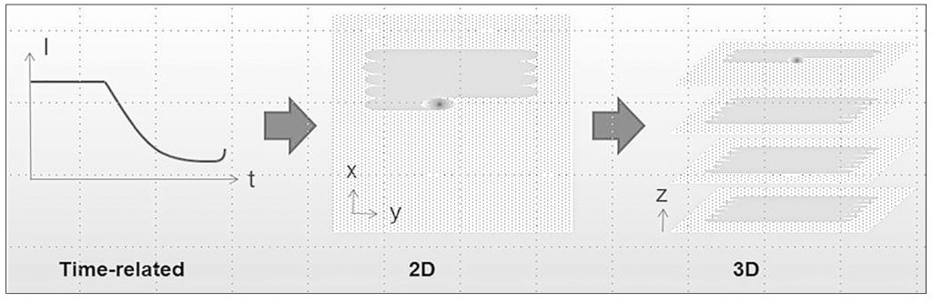
As previously stated, a low melt pool intensity may indicate inadequate laser output or an excessively high scanning speed, resulting in insufficient energy input. Moreover, changes in the area of the melt pool may indicate a variation in the oxygen content within the process chamber. The part geometry also has effects on the thermal conditions in the process, which means that reference samples and a high level of process understanding are required for the variation in data during the process to be interpreted and analysed correctly. In 2D melt pool monitoring, the signals are supplied as average values per component and per layer. This 2D perspective permits a restricted interpretation of localised defects.
Innovations in the QMmeltpool 3D system
The former time-related 2D monitoring of the build process has now become a position-related 3D landscape (Fig. 3). Instead of exclusively time-related data, the system now additionally delivers position-related signals for definitive allocation, comparable to CT. These signals make it possible to generate 3D datasets of the part or its structure. A highly accurate 3D landscape of the part is thus created. In detail, this means identifying characteristic properties of the melt pool. These include the area and intensity of the melt pool that can be investigated using two detectors, a camera and a photodiode, with a high resolution level in terms of location and timing. Following that, these signals are correlated with the corresponding positional data of the laser. This comparison is what makes QMmeltpool 3D so effective: melt pools signals such as melt pool area and melt pool intensity can thus be visualised and evaluated in three-dimensions directly after the build process has finished. The user can trace the process of creating each part in terms of position. Local effects in the part during the build process can now be detected and analysed more effectively.
Coaxial integration: pinpoint accuracy with the on-axis approach
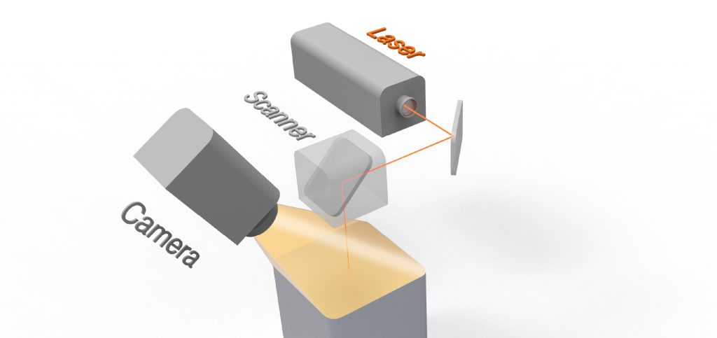
The new approach is based on expanding the 2D inspection into the 3D space, with coordinate-related data acquisition of the melt pool values. It is possible to look at current quality assurance approaches available on the market to assess the new method of QMmeltpool 3D. Traditional off-axis inspections have a lower resolution and lower detection rate. For example, an infrared-sensitive camera is used that is located in a position outside the build chamber (Fig. 2). The advantage of this ex-situ solution is that the system integration of the machine and camera is reasonably straightforward. An off-axis structure enables statements to be made about the overall fusing and cooling behaviour. However, it is not possible to derive a detailed statement about the melt pool.

The on-axis/in-situ structure is based on a two axial arrangement of detectors (Fig. 1). The detectors used are a camera and a photodiode, which use the same optic as the laser. This coaxial integration permits a high coordinate-related 3D resolution of 35 µm. The detection rate results from the scanning speed. If this speed is 1,000 mm/s, the result is 100 µm, i.e. the distance covered by each shot. At 2,000 mm/s, the value is 200 µm. Concept Laser specifies the sampling rate of the camera as > 10 kHz and that of the photodiode as 50kHz. The coaxial arrangement offers the advantage that the melt pool emissions are always focused on one point of the detectors and the frame size is reduced so that the sampling rate can also be increased. As a result, a detailed analysis of the melt pool characteristics is possible.
Possibilities and limitations
QMmeltpool 3D helps to minimise the work involved in quality assurance and to exploit time benefits. The system can supply local indications of defects in the part. As a result, subsequent inspections and tests can be reduced to a minimum. Furthermore, the data is available directly after the build process, resulting in savings in the time taken. The system is unable, however, to rectify defects during the build process. Due to the large number of influencing factors that can cause defects in the build process or on the component itself and the highly dynamic properties of the process, developing a self-correcting control loop represents a significant challenge.
Conclusion and outlook
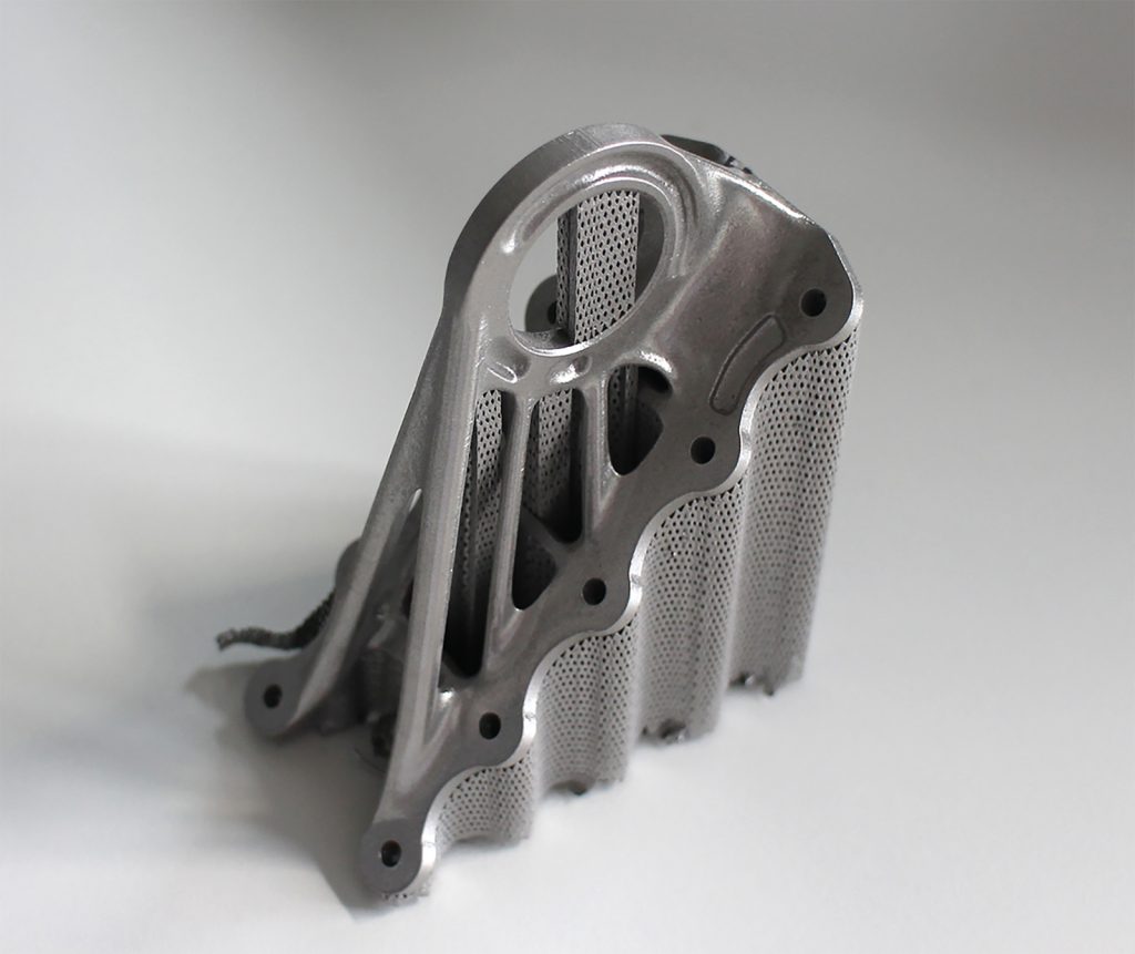
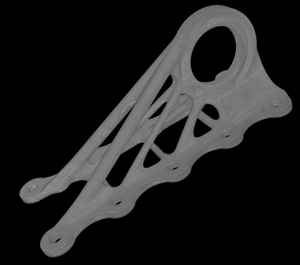
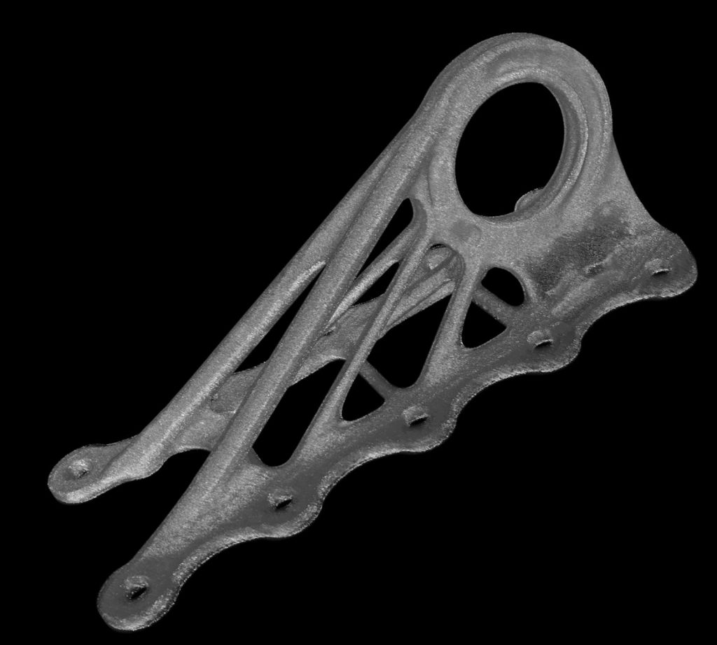
In-situ monitoring systems can detect process characteristics in real time thanks to their high resolution and sampling rates (every 0.1 mm, depending on the scanning speed) (Figs. 4 and 5). In-situ monitoring systems thus make a significant contribution to detecting process defects at an early stage and avoiding them in future. For the user, this represents a tool for optimising the process.
The practical added value of three-dimensional visualisation is not just that it is an original way of providing active quality assurance. In production and process development, component jobs can be optimised through iterative variation of the parameters. Support structures can be adapted and, above all, the design of the part can be structured in a more efficient and production-friendly manner. Last but not least, new possibilities are opened up in material research and validation of materials.

Contact
Concept Laser GmbH
An der Zeil 8
D-96215 Lichtenfels
Germany
Tel: +49 9571 1679 0
Email: [email protected]
www.concept-laser.de
LAST MONTH’S MOST-READ ARTICLES


