Multi-material metal parts by Powder Bed Fusion: New application opportunities
As product developers become more and more aware of the possibilities of metal Additive Manufacturing and the design freedom it offers, metal Laser Beam Powder Bed Fusion (PBF-LB/M) has established itself for series applications in numerous industries. One novel capability of PBF-LB/M which has yet to be fully explored is the production of multi-material metal parts, which would offer huge new potential for designers in many industries. Prof Dr-Ing Christian Seidel looks at methods and solutions for the AM of parts consisting of two arbitrarily distributed metal alloys and presents use cases with the potential for series production by multi-material PBF-LB/M in the near future. [First published in Metal AM Vol. 8 No. 2, Summer 2022 | 15 minute read | View on Issuu | Download PDF]

Additive Manufacturing has become increasingly important for production technology in recent years. In particular, metal Laser Beam Powder Bed Fusion (PBF-LB/M) has already made it into series production in industries such as aerospace, medical, and tool making, as well as general mechanical and plant engineering. Product developers appreciate the possibilities of Additive Manufacturing processes because of the high degree of design freedom they offer – for instance, the topology of a component in the force flow can be optimised according to the loads that occur, and the result can be additively manufactured more or less directly. A well-known example of this is the AM of titanium alloy brackets for aircraft. The possibility of function integration has also been exploited in numerous industries, since solid-state joints or porous structures can be manufactured in a targeted manner. Until now, however, these components have always been made from a single material.
A closer look at the industrial use of Additive Manufacturing reveals that series production has typically been realised in high-tech applications. This is not only because maximum design freedom is desirable in high-tech fields to achieve optimised device performance, but also because higher manufacturing costs are more likely be acceptable in such applications. The reason for this is that production costs can be compensated for, or even overcompensated, in a short time due to the ongoing savings achieved during the use of the component. Hence, a return-on-investment calculation becomes possible in which the increased cost of producing a component is exceeded by the saving achieved in a few years, months or even days. If, for example, a valve block is not manufactured conventionally by means of milling and drilling, but flow-optimised via Design for AM (DfAM), flow losses can be reduced. This may allow the use of a smaller pump in operation, thus saving not only on the investment but also ongoing energy costs. In view of the new possibilities we have seen these high-tech fields achieve using AM, it seems clear that these same fields would benefit from multi-material Additive Manufacturing.

As defined by ISO/ASTM TR 52912 [4], a multi-material component is characterised by the presence of at least two different materials that are firmly bonded together. The production of 2D multi-material components, in which a material change takes place in the direction of the build process between successive layers, can already be carried out today on most commercially available PBF-LB/M machines. To do this, a component is additively manufactured with ‘material 1’ up to the desired height for this material. Then the remaining material 1 powder is removed from the machine and, if necessary, the filter in the protective gas flow and the corresponding seal changed to fit ‘material 2.’ After this cleaning and setup process, Additive Manufacturing continues with material 2, with the previously manufactured part structure serving as the base body and replacing the typical build platform. In summary, additively manufacturing 2D multi-material parts in the improvised manner described is comparatively time consuming, but it is possible on typical PBF-LB/M machines thanks to a manual material change. For the manufacturing of a 3D multi-material component, state-of-the-art PBF-LB/M machines cannot be used, because both materials must be present within one layer. Accordingly, a 3D multi-material component is characterised by the fact that the material can be randomly distributed in the volume.
From mono-material to 3D multi-material PBF-LB/M

For the production of 3D multi-material components by means of PBF-LB/M, it is necessary to push the capabilities of commercially available PBF-LB/M machines on the software and hardware side and to adjust the typical process chain in every step, as shown in Fig. 2.

Pre-process
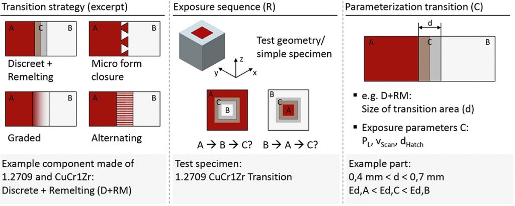
Firstly, the material distribution needs to be defined by the designer. This can be done either by applying the designer’s own expertise or using simulation tools (although a state-of-the-art review has revealed that the optimisation of material distribution within a part is not a standard feature of established Computer Aided Design [CAD] tools). Once the desired material distribution is known, three sub-models of the part need to be generated for the AM process, as shown in Fig. 3. For each material section, a separate model (sub-model) is needed in order to allow for a suitable parameterisation for solidification within PBF-LB/M. Fig. 3 shows a part containing a tool steel (1.2709) and a copper alloy (CuCr1Zr).
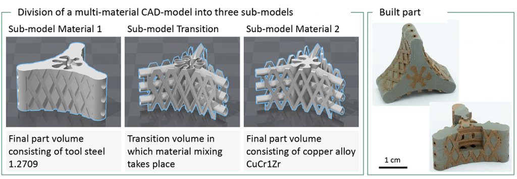
In addition to the sub-model generated per material, a third is required that geometrically describes the transition zone between materials. For each of these partial models, specific parameters are usually required for the build process in order to ensure that the materials produced are of sufficient quality. This means that, for example, laser power, scan velocity and hatch distance might vary for each material region in order to obtain high relative density values and crack-free material. This is due to the presence of different material characteristics in terms of powder properties, conductivity and absorptivity, amongst other factors. Furthermore, differences in part quality may be found depending on the exposure sequence; Fig. 4 shows an example for the material combination of tool steel (1.2709) and copper alloy (CuCr1Zr) shown in Fig. 3.
In-process
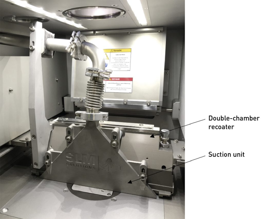
The most significant challenge in the multi-material PBF-LB/M process is to implement powder recoating for multiple materials. Typical recoating mechanisms do not provide for the application of two powder materials within one build job. For that reason, both the machine software and hardware need to be modified in order to enable recoating with multiple powders. Fig. 5 provides a view inside the build chamber of an SLM Solutions SLM® 280 2.0 machine at the Fraunhofer IGCV laboratory in Augsburg, Germany, that is capable of producing multi-material parts. The mechanism used within this machine follows the principle developed by Fraunhofer IGCV [1]. In short, a double-chamber recoater is used to provide two powder materials within one build job. In addition, the coating axes are equipped with a suction unit, which is able to remove a number of powder layers. The multi-material cycle thus follows these steps:
- Material A is applied in layer n and solidified according to its CAD design
- Unsolidified powder material A is removed by the suction unit
- Material B is coated in layer n and solidified according to its CAD design, unsolidified powder material B remains in the build chamber
- The build platform is lowered by one layer height and step 1 is repeated for layer n+1
Following the described principle in steps 1–4, material B remains in the build chamber whereas material A is constantly extracted by the suction unit.
Post-processing
Besides the challenges already familiar in mono-material processing, such as loose powder removal from the part or support structure removal, the separation of powder mixtures is the key additional challenge that comes with multi-material processing. Within the described coating process in steps 1–4, a mixing of the two powder materials cannot be avoided. This is a result of step 2, the removal of unsolidified powder material A using the suction unit. Theoretically, it is sufficient to remove exactly one layer of powder. This would completely remove material A from the build chamber and only material B would be left. Also, only material A would be left in the suction device. However, it was found that the current state of the art does not allow powder layers to be removed so accurately. The particle size distribution of the powder and the resulting particle masses, as well as the achievable uniformity of the suction device, limit accuracy and mean that, usually, three or more layer heights are suctioned to avoid contamination. Therefore, research was carried out into general principles that enable the recycling of powder mixtures, as shown in Fig. 6.
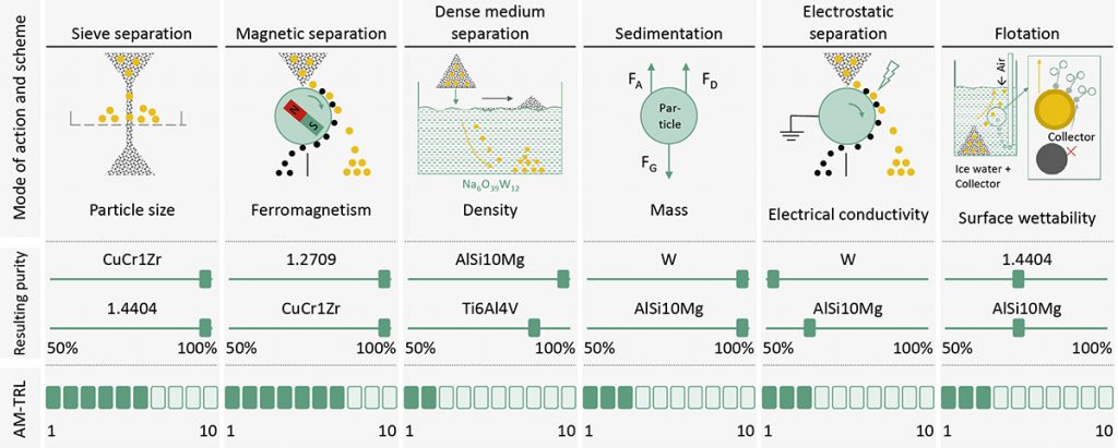
Various principles are known depending on the characteristics of the utilised powder materials. For example, if one powder material has magnetic properties, but the second powder material does not, magnetic powder separation can be used. If it is possible to process the powders in different and overlap-free particle size distributions, separation can also be carried out downstream by this difference using sieves. In addition, other physical principles are available (Fig. 6), but their current suitability for Additive Manufacturing is still significantly lower than that of magnetic separation or sieving (2). As demonstrated by [3], it is not always necessary to aim for a 100% separation of the powder materials in order to be able to reuse them again. The required level of purity is highly dependent on the material combination.
Industrial potential and examples of multi-material parts
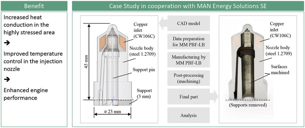
Multi-material components make it possible to make optimum use of material-specific advantages depending on the component requirements. For example, a wear- and heat-resistant steel can be combined with a copper alloy with good thermal conductivity for a large bore engine application. Fig. 7 shows a use case of an injection nozzle jointly investigated by Fraunhofer IGCV and MAN Energy Solutions SE. The multi-material design foresees a copper core in the highly stressed area leading to improved temperature control in the injection nozzle and in consequence enhanced engine performance. The shown part was additively manufactured following the procedure described above.

Fig. 8 shows a section of a gear wheel consisting of two steels. The procedure was as described in steps 1–4. In this case, material 2 was a powder mixture and was deposited in layers in the peripheral area of the gear. In material 2 powder, the carbon content (C content) was increased in advance by means of a graphite admixture. This resulted in a C content of approx. 0.2 wt.% in the interior of the component (material 1, 1.2344, H13) and 0.8 wt.% in the rim. The diffusion of the carbon during melting and heating as a result of laser exposure led to a graded transition between the two areas. The process used allows the thickness of the edge layer to be selectively set and adjusted. This makes it possible, for example, to produce an optimum hardness profile at the tooth flank and at the same time a hardness profile in the tooth root that is optimised for load-bearing capacity. In addition, the procedure shown here can be used to create struts inside the component (Fig. 8b). Subsequent case hardening is not necessary. Only heating and quenching is required to produce a complete martensitic surface layer. The result shown here, therefore, has potential for gear manufacturing.

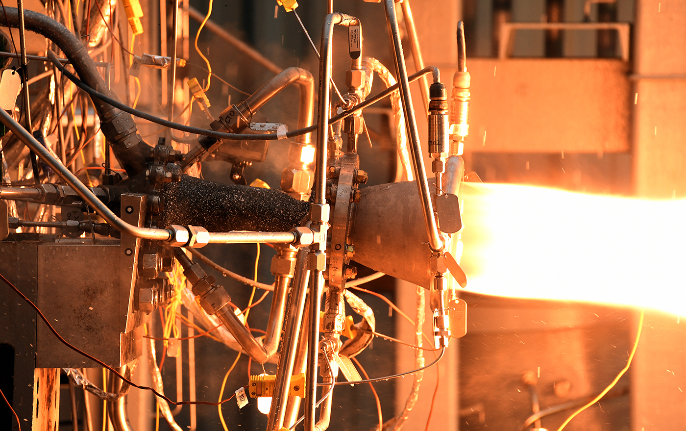
Fig. 9 is an example from the space industry. Combustion chambers are faced with high thermal loads, but also need to be as light as possible. The more performant a chamber can be built, the better for the rocket. The less mass is needed for the required thruster chamber, the more pay load can be sold to customers for the transportation to space. Therefore, increased manufacturing costs can be overcompensated by more load that can be brought to space. For these reasons, space is one of the core industries for Additive Manufacturing in general, and multi-material Additive Manufacturing in particular. In the example shown, a nickel-base alloy would serve as the heat-resistant base body of the chamber and copper-based regions are foreseen to increase heat transfer.
However, the potential for multi-material components is by no means fully described with the components shown in this article. For example, for an injection moulding application, an abrasion-resistant tool steel can be combined with a copper alloy with good thermal conductivity, significantly reducing cycle times in the production of plastic components with high aspect ratios. The combination of aluminium and copper alloys offers opportunities for cost savings in electric motor manufacturing. Furthermore, the advantage of combining a titanium alloy with tantalum can improve dental implants.

In summary, the current state of multi-material processing is mature enough to investigate industrial applications. It is now well known what can and cannot work. For example, it has become apparent that the technological readiness for certain material pairings, such as copper and steel, is sufficient to enable industrial applications. This is due to the fact that the Additive Manufacturing process itself can be mastered. Equally relevant is that with this material pairing, it has been shown that the powder materials mixed in the build-up process can subsequently be sorted with a purity of almost 100% by utilising magnetic separation. In contrast to the material combination steel-copper, the current state of the art makes it difficult to combine materials that are very similar in all respects (e.g., density, magnetisability, grain size distribution). In this case, powder separation is difficult and multi-material processing is therefore not very economical as the reusability of the powders is usually regarded as a central criterion for the economic efficiency. At the same time, however, it is reasonable to ask what advantage multi-material processing would offer in this scenario, since if materials are very similar, synergy effects are limited. The combination of metal alloys with technical ceramics also does not seem to make much sense at present, since the quality of laser-based processed ceramics (e.g., Al2O3) do not meet the typical requirements and processing is not very stable. However, the suitability could be demonstrated for electrically insulating (thin) structures in metal components.
Conclusion
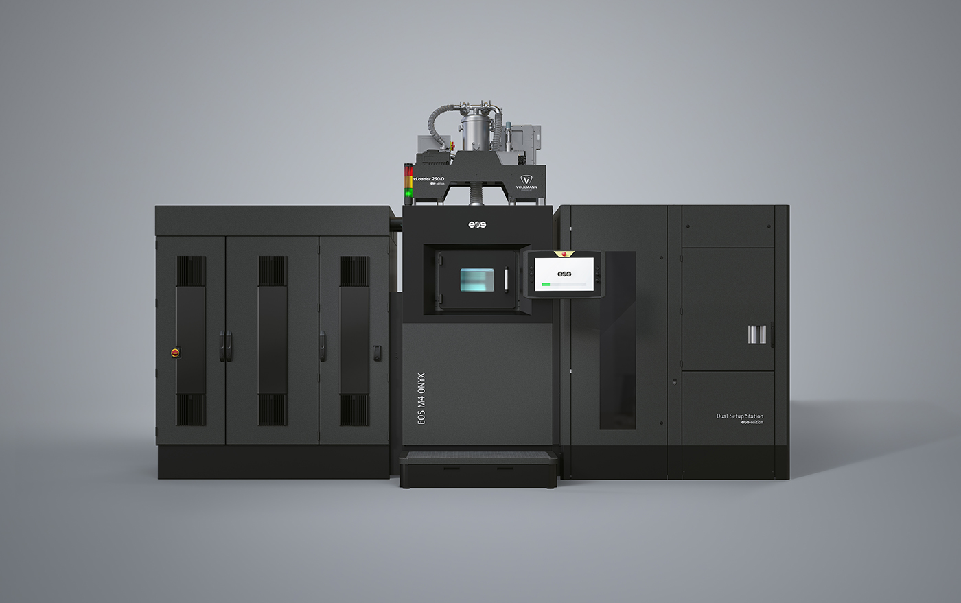
As expected, the technology readiness level of multi-material PBF-LB/M is still lower today than that of mono-material PBF-LB/M. Nevertheless, the example of various industrial applications has shown that now is the time to transfer the topic from research to the targeted development of commercial applications. The basic feasibility has been demonstrated in all areas of the additive process chain and first industrial machinery is available on the market. For a broad industrial application, it is now necessary to address product-specific requirements. In most cases, the foundations for this are available via scientific publications. For this reason, it can be summarised that multi-material processing provides companies, especially in the high-tech segment, with an excellent opportunity for a market advantage in future series products.
Acknowledgements
The author expresses his sincere thanks to the Free State of Bavaria and its Bavarian Ministry of Economic Affairs, Regional Development and Energy for funding the MULTIMATERIAL-Zentrum Augsburg (Multi-material Centre Augsburg). Furthermore, the author thanks Max Horn and Matthias Schmitt for contributing to the figures.
References
[1] ‘Fabrication by Laser-Beam Melting Using the Example of Metallic Compounds with the Copper Alloy CW106C,’ Anstaett, C, Multi-Material Dissertation Technical University of Munich, 2020, http://mediatum.ub.tum.de/?id=1524471.
[2] Powder Separation Strategies for Recycling in Multi-Material Additive
Manufacturing, Horn, M, Prudzilko, P, Anstaett, C, Lutter-Guenther, M, Seidel, C, Reinhart, G, published in the proceedings of Euro PM2018 – Special Material III
[3] ‘Cross-Contaminations in Powder Bed Fusion: Influence of Copper Alloy Particles in Nickel-Base Alloy Feedstock on Part Quality,’ Horn, M, Langer, L, Dietrich, S, Schlick, G, Seidel, C, January 2020, SSRN Electronic Journal
[4] ISO/ASTM TR 52912:2020 Additive Manufacturing – Design – Functionally graded
[5] Additive Manufacturing
Animation Fraunhofer IGCV Coating principle https://www.youtube.com/watch?v=pm62sRQOUgE
Author
Prof Dr-Ing Christian Seidel
Christian Seidel is a full professor for Manufacturing Technologies and Additive Manufacturing Processes and Head of the Smart Manufacturing Lab at Munich University of Applied Sciences. In addition, he serves as Head of Additive Manufacturing Research at Fraunhofer IGCV (Augsburg/Munich) and Chairman of ISO/TC261 Additive Manufacturing. He also holds several positions in both academic and industrial networks.
LAST MONTH’S MOST-READ ARTICLES