Separation anxiety: Lessons learned at NASA from a developmental rocket engine failure
So much is discovered when it just all goes wrong. From a 'design-fail-fix' perspective, it's expected that developmental components may be pushed to destruction. With rocket engines that operate near the limits of their performance, however, the need to understand the causes of a failure is critical. In the competitive commercial space business there's a clear advantage not to disclose knowledge gained from such incidents. Thankfully, NASA can share what others cannot. Here, Alison Park, Deputy Technical Fellow, Materials and Additive Manufacturing, and Paul Gradl, Principal Engineer, share insights into one failure. [First published in Metal AM Vol. 9 No. 1, Spring 2023 | 20 minute read | View on Issuu | Download PDF]
Have you ever thought about the 1960s Apollo programme and the feat accomplished to put humans on the moon? These were the days of vellum drafting tables and parts made on manual machines. What would the engineers of the Apollo programme think about the proliferation of various Additive Manufacturing technologies inserted into the design and development of rocket propulsion systems? Would the multiple developmental rocket engine failures still have happened as the teams tried to understand in parallel the complex physics of space flight and hardware design? Could they have executed the design-fail-fix cycle faster if had they had access to Additive Manufacturing? [1]
It is fascinating to imagine what might have been possible if AM had been available to face some of the fundamental technical problems that stood between the Apollo engineers and success. However, even with the benefits of AM fully realised in design, testing, and production, the physics of rocket engines are still challenging to overcome. The environments rocket engines must perform in are extreme: if something can go wrong, it will.

It is necessary, then, that the important groundwork, process control, and critical integration needs are methodically implemented. What becomes evident very quickly is that designing, manufacturing and assembling parts into a complex rocket propulsion system involves significant resources – time, funding, and skillsets – to meet the end goal, which is always one thing: a safe and successful mission.
NASA’s Marshall Space Flight Center (MSFC) in Huntsville, Alabama, USA, provides the expertise and capabilities to shape nearly every facet of the nation’s ongoing mission of space exploration and discovery. Whether it’s propulsion systems, space habitats, planetary landers, or cutting-edge technology to guide scientific missions, Marshall powers the future of space exploration.
NASA MSFC is now taking full advantage of AM for rocket propulsion systems to reduce time-to-test and iterations through the design-fail-fix cycle. Other advantages of AM have been realised for rockets, including overall cost and schedule reductions, consolidation of parts, complex features, and using novel AM alloys to increase performance. One technology maturation effort to help advance AM was the Long Life Additive Manufacturing Assembly (LLAMA) under NASA’s Game Changing Development (GCD) programme [2].
The objective was to evaluate the feasibility of Laser Beam Powder Bed Fusion (PBF-LB) with the GRCop-42 (copper-chrome-niobium) alloy for the fabrication of high-duty cycle lunar lander-sized rocket combustion chamber assemblies. The project’s tasks included developing and maturing the PBF-LB process and the GRCop-42 alloy, performing design and analysis of the hardware, managing the procurement and integration of hardware requirements, and running a series of hot-fire testing of the sub-assemblies. The goal of the hot-fire test series was to meet a minimum of fifty starts on a single chamber assembly.
Rocket thrust chamber assembly development under the LLAMA project
A typical rocket thrust chamber assembly (TCA) for chemical propulsion has three major sub-components: the injector, the combustion chamber, and the exhaust nozzle. The goal of the TCA is simply to generate thrust by providing a volume for combustion and converting the thermal energy to kinetic energy [3]. The combustion chamber and exhaust nozzle are most often regeneratively cooled using complex internal coolant channels for high-performance, high-pressure engine systems.

The combustion gas temperature can approach 3,300°C and pressures can often exceed 50 Bar. Without active cooling of the chamber walls using the propellant(s) from the system, the chamber would melt almost instantaneously; but these chambers are designed with walls that are only a few sheets of paper thick, making traditional manufacturing a challenge. This was a huge opportunity to introduce PBF-LB, to create these complex coolant channels with fine features for the chamber, and it has become a prevalent practice in the commercial space sector.
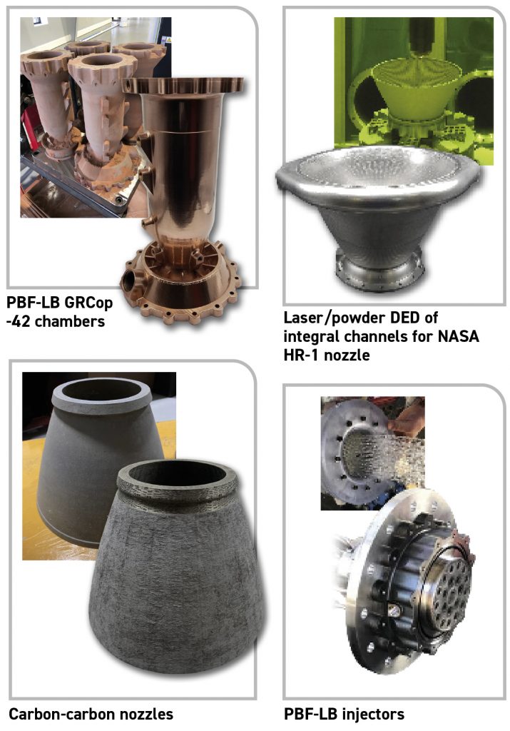
The injector is no simple feat either and, when conventionally manufactured, often contains hundreds of components brazed or welded together; AM has simplified this process. Regeneratively cooled nozzles present similar challenges to cool the wall as the combustion chambers, but must be manufactured on a grander scale. The LLAMA project set out to design and test all these AM components using PBF-LB for the injector and chamber and Laser Beam Powder Directed Energy Deposition (DED-LB/powder) for the regeneratively-cooled nozzle [4]. Fig. 2 shows some examples of LLAMA TCA components. In addition to the aforementioned AM techniques, advanced carbon-carbon uncooled nozzles were fabricated and tested.
The alloy selected for the combustion chamber was GRCop-42 (Cu-4 at.% Cr-2 at.% Nb). GRCop-42 was developed by the NASA Glenn Research Center (GRC) in the mid-1980s, along with alloy GRCop-84 (Cu-8 at.% Cr-4 at.% Nb) [5]. The GRCop-alloys are copper-based alloys that use chromium-niobium (Cr2Nb) precipitates for dispersion strengthening [6]. GRCop-42 possesses desirable material properties such as high thermal conductivity, high creep resistance, extended low-cycle fatigue life, enhanced oxidation resistance, and high tensile strength at elevated temperatures approaching 800°C [7]. These material attributes remain when processed using PBF-LB, and it has been an alloy of choice for TCAs following its development in 2019.
Successful hot-fire testing of AM TCAs
NASA has accumulated over 40,000 seconds and over 1,100 starts on multiple GRCop-42 and GRCop-84 combustion chambers. This includes a single 10 kN thrust GRCop-42 chamber, produced by PBF-LB, that accumulated over 188 starts and greater than 8,030 seconds. Every one of those seconds was counted meticulously.
Although hot-fire testing of chemical propulsion systems may seem like a regular occurrence, it is not for the faint of heart. The propulsion environment is harsh. Adrenaline and tensions run high, as do expectations. As an engineer, you face an overabundance of design decisions, and the time and financial investment drive high expectations. Component integrations are complex. Things can go wrong in milliseconds; in the thrill and rumble of the engine, you forget to breathe.

When the LLAMA project successfully tested a TCA, the team breathed a little bit easier after obtaining fifty-one starts to meet the goal of the project. This success led the team to test a second chamber, fabricated on the same build plate as the first (and two others), using identical processing steps. This test series was expected to provide additional process data on repeatability and performance metrics.
…and one failure
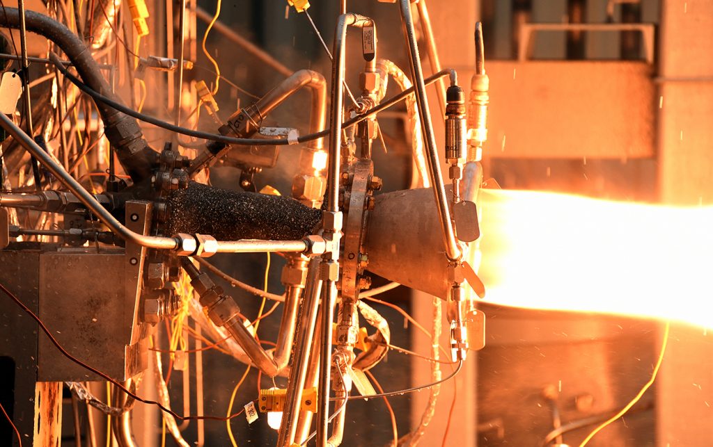
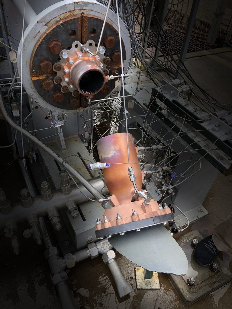
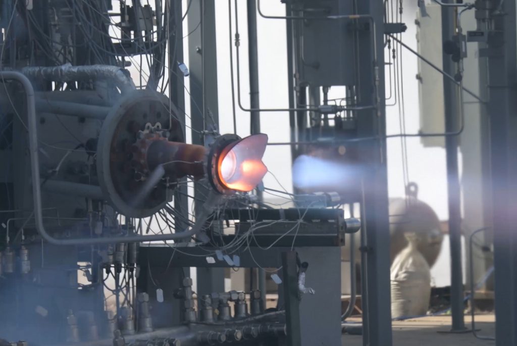
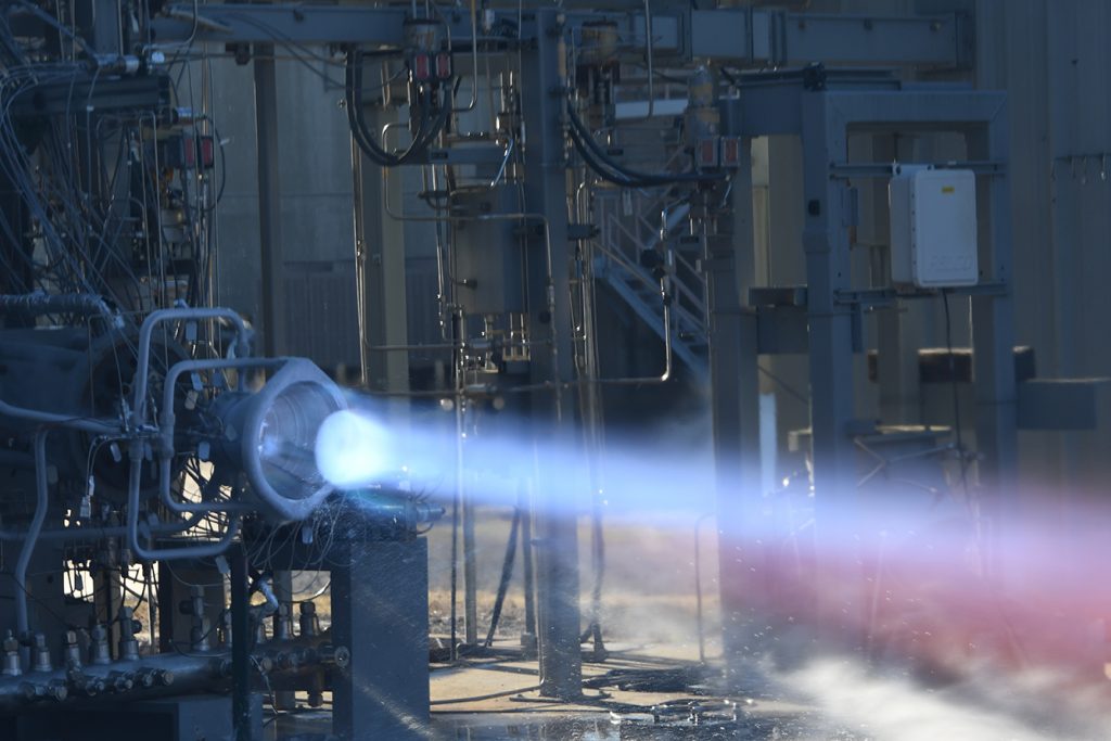
In February 2021, NASA initiated the test series at Marshall Space Flight Center’s Test Stand 115 (TS115), with liquid oxygen and liquid methane as the propellants. The team experienced the adrenaline-filled emotions typical during this type of experimental hot-fire testing. Identical conditions were being run on the second LLAMA chamber, which had successfully been tested eight times prior (Fig. 3). This test started as routine and typical – until it wasn’t.
This LLAMA TCA experienced no issues during start-up and achieved steady state chamber pressure in less than one second. Following steady state, the test ran for almost nine seconds – then, an experimental carbon-carbon (C-C) nozzle extension began to fail. This C-C nozzle extension failure was expected, as it had reached its predicted life limit, so there was little concern and the test continued to run.

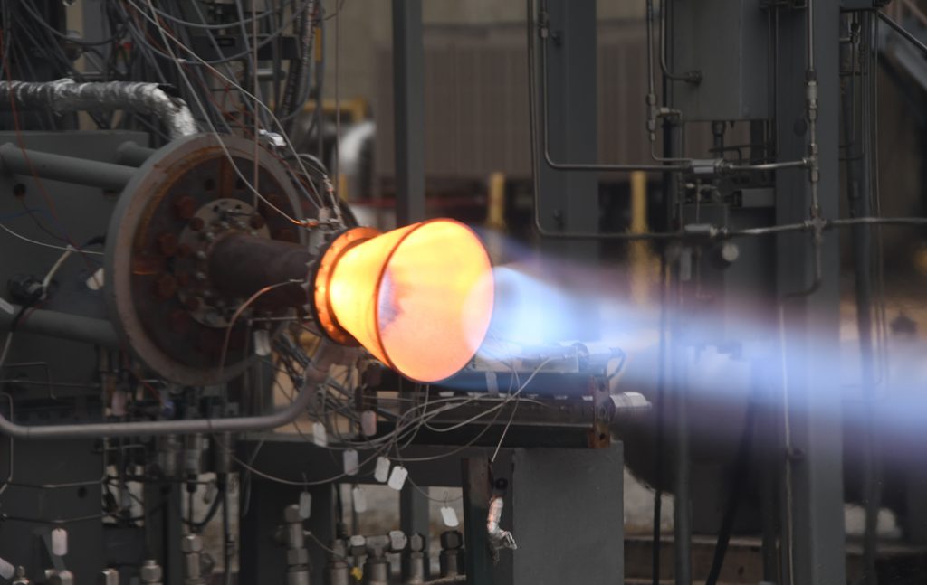
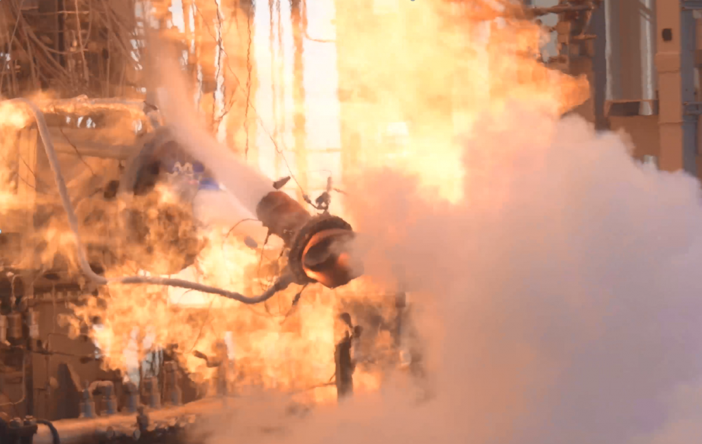
At approximately eleven seconds into the test, hot gases spewed from the fire-breathing chamber and it was fully engulfed in flames (Fig. 4). This was no longer a normal test, but a premature disassembly. The thrill and excitement of testing turned into instantaneous concern. The test was shut down immediately and safely per the proper commanded sequence. The team plans for these types of failures, but rarely is the protocol used.
Immediately, the team observed on the remote cameras in the test control centre that the chamber was split in half. After the test stand was cleared for personnel, the hardware and surrounding area were inspected. There was no damage to test stand equipment, personnel, or area wildlife. The team looked, puzzled, at what lay in front of them; the chamber was cleanly separated, as if it had been sawed in half (Fig. 5).
This separated chamber and C-C nozzle extension were secured to preserve the fracture surfaces from the as-failed condition, and this anomalous test occurrence prompted a deep process evaluation. The engineers who were close to the AM process and observed this failure were suspicious as to how clean the break was. Could it have been caused by witness lines from the build?
Evaluating the test failure
The evaluation looked at all aspects of the test history, sequencing, hardware, AM build process, inspections, and any additional records [8]. A visual crack and subsequent leak was observed in the high-speed video upon review (Fig. 6). This opening in the chamber quickly grew and, in 300 milliseconds, the chamber separated in the barrel section completely.
The first step in the evaluation was to collect the history of the chamber’s processing steps, including the powder feedstock, AM process, and post-build process, including Hot Isostatic Pressing (HIP), machining, cleaning, and inspection data. This subject chamber was built along with three other chambers – two of which were identical build models – on the same build plate. The ‘twin’ chamber had just completed an extensive hot-fire test series and accumulated fifty-one starts and nearly 1,000 seconds.
Further investigation into the build records indicated interesting information about the four chambers. There had been both intended and unintended build interruptions during their manufacture. The history of these interruptions was present as witness lines on the hardware, shown in Fig. 5. Other than these interruptions, the build records indicated no anomalies, the HIP parameters were correct, and the other post-processing operations were all as expected.
Witness lines are defined as clearly distinguishable lines on the surface of an AM part that run parallel to the build plane. These are caused by variations in the layer scanning time (where parts may cool) and layer thickness, and are typically formed during build stoppage and interruption events. The height of each of the visible witness lines was measured and correlated exactly to layers with the slices indicating build stoppages (Fig. 7). While the witness lines looked similar, the mechanisms for each were different and resulted in a different environment.
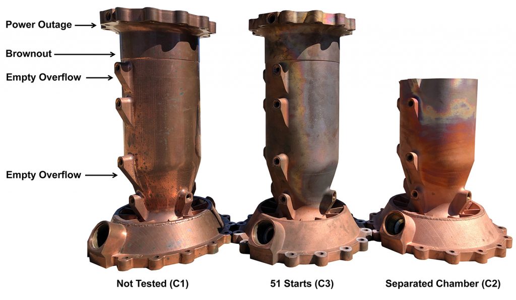
For instance, the emptying of the PBF-LB machine’s overflow caused the parts to be exposed to an open atmosphere for less than sixty minutes each. Where build interruptions were caused by power failures, the PBF-LB build chamber remained sealed, but did not have an active purge. The brownout interruption was ten minutes and the power outage was less than 120 minutes.
It was the second ‘empty overflow’ build interruption, located in the barrel section of the chamber, that correlated exactly to layers with slices of the separated chamber 2 and thus received a lot of attention. The team used the ‘sister’ chambers that were additively manufactured along with the failed chamber to help evaluate the material and processing. One sister chamber (C3) was tested and the other chamber (C1) untested. These chambers allowed for the characterisation of the exact witness line locations to determine flaws, microstructure, chemistry, and mechanical testing to understand the failure and provide an extensive set of data.
The fracture surfaces of the failed chamber (C2) were evaluated following the separation event. When first observed with the naked eye, it was evident the fracture surface was planar, but there were two distinct areas that had been slightly deformed into a cup shape. These ‘cupped’ areas were roughly in the same circumferential position where the leak was first observed during the test. Under an optical microscope, the fracture surface showed the scan pattern as parallel lines across the surfaces. This could indicate that the build restart at this witness line created a severe lack of fusion between particles which may have led to reduced mechanical properties.
There was also evidence of some unmelted GRCop-42 powder particles. Under a Scanning Electron Microscope (SEM), the fracture surface showed irregular pore shapes and lower degrees of deformation prior to fracture due to a higher level of porosity and lack of powder particle fusion. Chemistry analysis via Inductively Coupled Plasma (ICP) and Inert Gas Fusion (IGF) showed the chamber had slightly higher oxygen levels and higher chromium/niobium ratio than were required by the specification target. This was also indicated in the chemistry for the powder certification. It is known that excess oxygen can reduce conductivity, high temperature strength and creep resistance leading to fatigue crack initiation sites.
To fully answer how these types of build interruptions and re-start events could have contributed to the reduced mechanical capabilities at the witness line, micro-tensile coupons were extracted directly from the chambers (Fig. 8). In addition to these samples, simulated build stoppage samples were built that emulated the power outage environment and time, as well as the powder overflow event and time. From these simulated samples, tensile and low cycle fatigue (LCF) mechanical testing was conducted to determine the impact of the build interruptions and restarts.
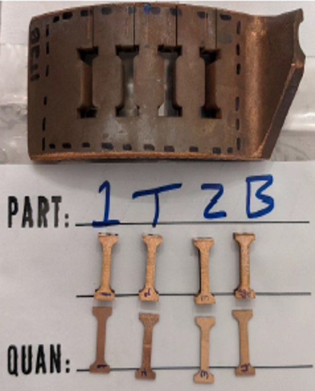
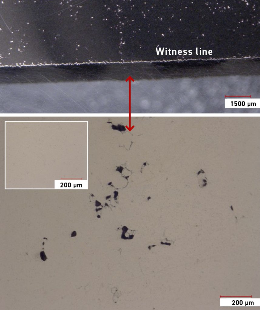
The micro-tensile specimens excised at the witness lines of the chamber (C1) indicated higher porosity approaching 2% compared to the rest of the chamber (0.5%) as shown in Fig. 9. Even the 0.5% porosity was extremely high compared to the near 100% density observed in typical PBF-LB builds of GRCop-42 (post-HIP). Sections were taken from the chambers and these samples were mounted, polished, and optical microscopy images were collected. It was evident from these images that the material had higher randomly distributed porosity throughout, but also showed the congregation of porosity around the witness lines.
Micro-tensile test results showed a reduction in Ultimate Tensile Strength (UTS) by 30% compared to a controlled sample taken in an area not affected by the witness line. The strain to failure was also reduced by 80%, indicating a brittle material condition. This could have contributed to the reduced load-bearing capacity at the witness lines along with cyclic strains at the weakened joint.
The tensile test data from the chamber initially led the team to believe that build interruptions could cause a reduction in properties, but the tensile test data from the simulated build stoppage specimens told a different story. The average tensile data from the emulated samples with power outage and powder overflow events were nearly identical to the control specimens (no build interruption), as seen in Fig. 10.
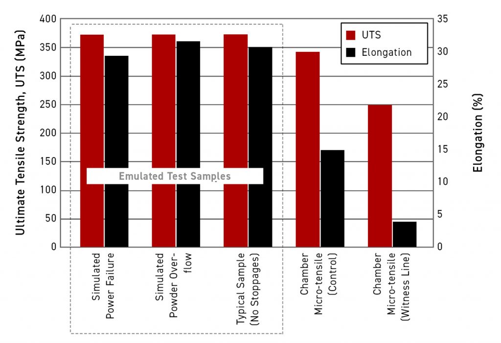
The ultimate strength (UTS,) yield strength (YS), and elongation indicated no differences. The coupons exhibited close to 100% density and acceptable tensile properties results. LCF testing was also completed and indicated no difference in fatigue life between the different types of restarts and control specimens. This emulated sample data confirmed that parts showing the witness lines after a proper restart procedure do not inherently possess weakened material properties. There may have been other contributing factors, operational and/or process sensitive, that contributed to the increased level of porosity on the witness line: the layer of the chambers remelted after the restart procedure.
The emulated tensile and fatigue samples along with the chamber tensile samples were subjected to post-mortem fractography (Fig. 11). The emulated samples with witness lines along with the control were consistent with expected fracture surfaces with a ductile failure: the typical cup and cone. The micro-tensile sample used as a control, from an area with no witness lines, also indicated deformation and necking before rupture. The fracture surfaces from the witness line of the C1 chamber micro-tensile samples revealed highly granular but less deformed fracture surfaces, a large quantity of unmelted powder particles, irregular-shaped porosity, and visible scan/melt pattern.
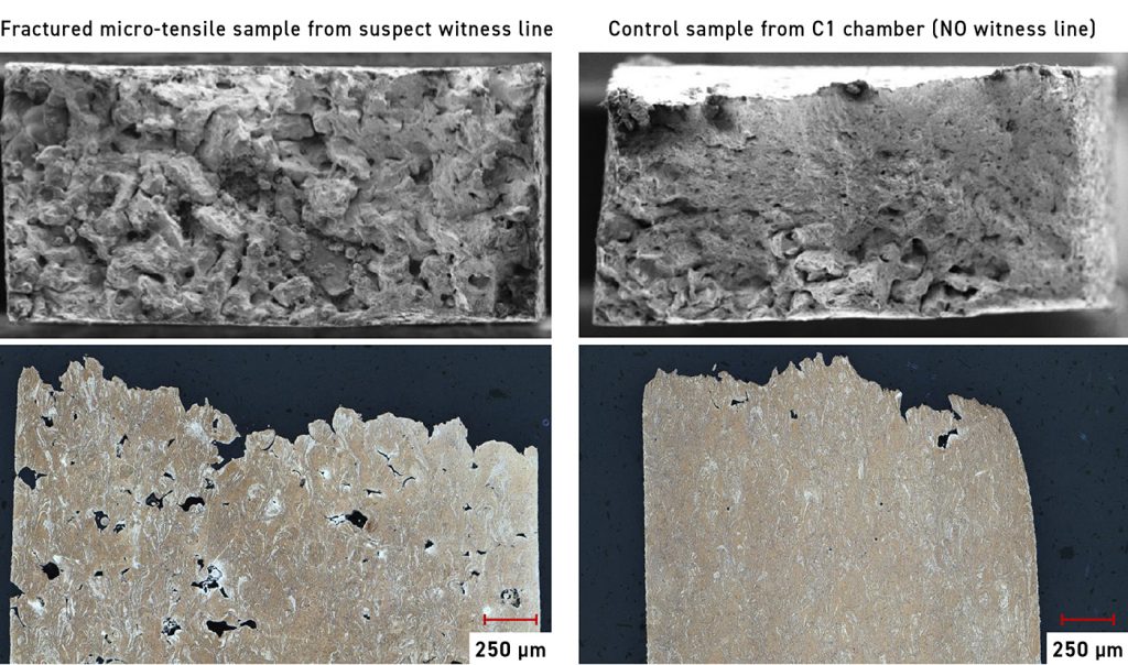
This suggested that the porosity observed was from a lack of fusion and not enough energy present to fully melt the powder and layers. This observation left the team a bit perturbed since all build records indicated proper operation of the machine. The PBF-LB parameters and hardware used had built dozens of combustion chambers previously, with the same GRCop-42 alloy, that were near 100% density and successfully tested.
Failure evaluation findings
The findings from this evaluation indicated several contributing factors leading to the failed chamber. Large pores were heavily concentrated at the build interruption witness lines. These did not completely close during the HIP process due to their size, which reduced the load-bearing area around the witness lines. This reduction in load-bearing area, along with thermal and structural fatigue of these surfaces, resulted in an overload during hot-fire testing. The porosity in the chambers was found to be much higher overall than typical PBF-LB builds with GRCop-42. It was also observed that the porosity increased with the height of the build.
The developmental path any AM user takes to prepare for part production will vary depending on the requirements and end goal of the project. It might be an early development part used to iterate design prototypes or a critical component used for crewed spaceflight. Whatever the path may be, the key lesson one can learn from our chamber’s ‘premature disassembly’ is that the AM user needs to have a thorough understanding of the entire AM process [9]. Small changes in parameters, feedstock, or other processing can impact the integrity of the part. This, of course, is known and observed in all manufacturing operations, not just AM.
NASA is investigating various AM processes as they rapidly advance, and is currently using them to produce components used in development and in critical spaceflight applications. NASA also works with commercial industry partners to insert AM design and hardware into spacecraft and launch vehicle systems. Therefore, NASA advocates that the qualification and certification of the materials and processes used to produce AM components are critical to their safe use.
To support the certification of AM processes and materials, NASA has developed a technical standard titled NASA-STD-6030 ‘Additive Manufacturing Requirements for Spaceflight Systems’, which establishes the policy framework for the development and production of AM hardware [10]. The backbone philosophy of NASA-STD-6030 is the understanding that AM materials are highly process sensitive, so a sound foundational process control logic provides the basis for reliable part design and production.
Such process development and definition activities prior to embarking on ‘flightworthy’ level production are necessary to ensure sufficient quality. While the LLAMA chambers were not subject to the requirements of NASA-STD-6030 for this experimental test series campaign, the chamber test failure is illustrative of the rationale behind several of the requirements established in NASA-STD-6030. This failed chamber provides an excellent case study for robust process development and in-depth material performance evaluation.
Due to the nature of current Additive Manufacturing machines or a particular part geometry, build restarts may be unavoidable. NASA-STD-6030 introduces several requirements relative to process restarts, as build interruptions may be associated with a higher risk of detrimental material flaws relative to the nominal, steady-state operation of the AM process. Therefore, it is crucial that a suitable build restart procedure be developed and documented for each alloy if build restarts are to be allowable for a component build.
The restart procedures should include – but are not limited to – recording the reason for the stop, maximum allowable stop time, build platform cooling limits, location of the stop, and the condition of the last part layer. A proper restart study includes mechanical test data and microstructural characterisation, destructive article evaluations, visual and volumetric inspections, and in-situ monitoring system data (if available). This provides a team with the necessary information to ensure transferability of the restart procedure to a desired component geometry. A list of criteria and qualified procedures should be agreed upon before the build is initiated.
If unplanned build interruptions happened within a flight-hardware production setting, those interruption events are required to be documented and dispositioned as a nonconformance in the build production. Regarding the LLAMA chambers, though these parts were manufactured in a non-flight hardware production setting, had pre-test examinations of the witness lines or some in-situ Non-Destructive Evaluation (NDE) of the chambers between restarts been performed, then the significant lack-of-fusion flaws could have been discovered at the middle witness lines on the observed chambers. This may have been grounds for a ‘non-conformance build’ disposition.
However, the observations of the top and bottom witness lines, which exhibited only minor geometric offsets and no surface-connected porosity, may have supported a ‘use-as-is’ disposition (had the middle witness line not been present). This illustrates the careful and rigorous practice needed to manufacture high-value/mission-critical components, especially if one wants to preclude undetected failure modes, such as those identified in the LLAMA chambers, to prevent potentially catastrophic consequences.
Conclusion
Rocket engines are unforgiving. The LLAMA project proved this, despite the team initially testing a chamber fifty-one times to meet project goals. All the hard work in design, analysis, fabrication, assembly and process planning culminates at the test stand, where the goal is to push components to the edge of their operational limits. Successes are rewarding, even when hot-fire tests last only for a few seconds. Failures are humbling and, though they can happen in milliseconds, they offer learned experiences for decades to come.
The Apollo engineers of the 1960s experienced many failures, but they persevered, even without cool AM machines at their disposal. We can embrace their positive thinking, adaptability, teamwork, and the mindset which saw them turn their failures into opportunities to learn and improve so that future failures can be prevented.
The first step is admitting to these failures. Our goal in admitting this failure is to start a conversation. We believe that lessons are learned the hard way and carried forward into all future designs, bringing us a step closer to success. NASA has a unique role to play in AM’s development and infusion into flight systems, and educating the industry about the process to get there. We believe that getting there will eventually lead us to establish a permanent human presence on the Moon and begin our human exploration of Mars. AM must, therefore, be applied in a methodical and safe manner.
Authors
Alison Park, Paul Gradl
National Aeronautics and Space Administration (NASA)
Acknowledgements
The authors would like to thank Ben Williams for leading the evaluation team and team members including Will Tilson, Colton Katsarelis, Gabe Demeneghi, David Ellis, TS115 crew, David Myers, Scott Ragasa, MSFC NDE Team, and various industry partners and test labs.
References
[1] S.C. Fisher, S.. Rahman, Remembering the Giants: Apollo Rocket Propulsion Development., 2009. https://ntrs.nasa.gov/citations/20100027314.
[2] P.R. Gradl, J. Fikes, Long Life Additive Manufacturing Assembly (LLAMA), NASA. (2020). https://www.nasa.gov/directorates/spacetech/game_changing_development/projects/LLAMA.
[3] D.K. Huzel, D.H. Huang, Modern Engineering for Design of Liquid-Propellant Rocket Engines, American Institute of Aeronautics and Astronautics, Reston, VA, 1992. https://doi.org/10.2514/4.866197.
[4] P. Gradl, D. Tinker, A. Park, O. Mireles, M. Garcia, R. Wilkerson, C. Mckinney, Robust Metal Additive Manufacturing Process Selection and Development for Aerospace Components, J. Mater. Eng. Performance, Springer. (2021). https://doi.org/10.1007/s11665-022-06850-0.
[5] R.P. Minneci, E.A. Lass, J.R. Bunn, H. Choo, C.J. Rawn, Copper-based alloys for structural high-heat-flux applications: a review of development, properties, and performance of Cu-rich Cu–Cr–Nb alloys, Int. Mater. Rev. (2020). https://doi.org/10.1080/09506608.2020.1821485.
[6] P.R. Gradl, S. Elam Greene, C.S. Protz, D.L. Ellis, B.A. Lerch, S.E. Greene, C.S. Protz, D.L. Ellis, B.A. Lerch, I.E. Locci, Development and Hot-fire Testing of Additively Manufactured Copper Combustion Chambers for Liquid Rocket Engine Applications, 53rd AIAA/SAE/ASEE Jt. Propuls. Conf. (2017) 1–27. https://doi.org/10.2514/6.2017-4670.
[7] P.R. Gradl, C. Protz, K. Cooper, C. Garcia, D. Ellis, L. Evans, GRCop-42 development and hot-fire testing using additive manufacturing powder bed fusion for channel-cooled combustion chambers, in: AIAA Propuls. Energy Forum Expo. 2019, American Institute of Aeronautics and Astronautics Inc, AIAA, 2019. https://doi.org/10.2514/6.2019-4228.
[8] B. Williams, P. Gradl, W. Tilson, C. Katsarelis, G. Demeneghi, D.C. Ellis, L-PBF GRCop-42 Chamber Witness Line Process Evaluation, in: JANNAF Jt. Propuls. Conf., JANNAF, Huntsville, AL, 2022.
[9] Paul R. Gradl, Omar R. Mireles, Christopher S. Protz, Chance P. Garcia, Metal Additive Manufacturing for Propulsion Applications, 1st ed., American Institute of Aeronautics and Astronautics, Inc., Reston, VA, 2022. https://doi.org/10.2514/4.106279.
[10] National Aeronautics and Space Administration, NASA-STD-6030, Additive Manufacturing Requirements for Spaceflight Systems, 2021.

LAST MONTH’S MOST-READ ARTICLES