Optimising powder removal in PBF-LB Additive Manufacturing: A Digital Twin approach
As Additive Manufacturing pushes the boundaries of design, post-processing remains a major challenge – in particular powder removal in Laser Beam Powder Bed Fusion (PBF-LB). But what if the digital twin of a part could not only optimise its design, but also predict and streamline powder removal? Here, Joseph Kowen explores how Solukon’s SPR-Pathfinder software achieves this, using advanced simulation to map powder flow and automate depowdering, ensuring that even the most intricate designs remain manufacturable. [First published in Metal AM Vol. 11 No. 1, Spring 2025 | 10 minute read | View on Issuu | Download PDF]
Advocates of Additive Manufacturing have long claimed that ‘complexity is free’ when it comes to AM design. The economic argument embedded in this statement is that AM allows for the production of complex products without significant increases in cost or effort. In conventional manufacturing, adding complexity, such as intricate designs or customisation, usually increases costs significantly. Since Additive Manufacturing builds parts layer by layer from the bottom up, as the promise goes, even the most unconventional engineering concepts can be brought to life with a simple click in Computer-Aided Design (CAD) and ‘printed’ with little further thought.
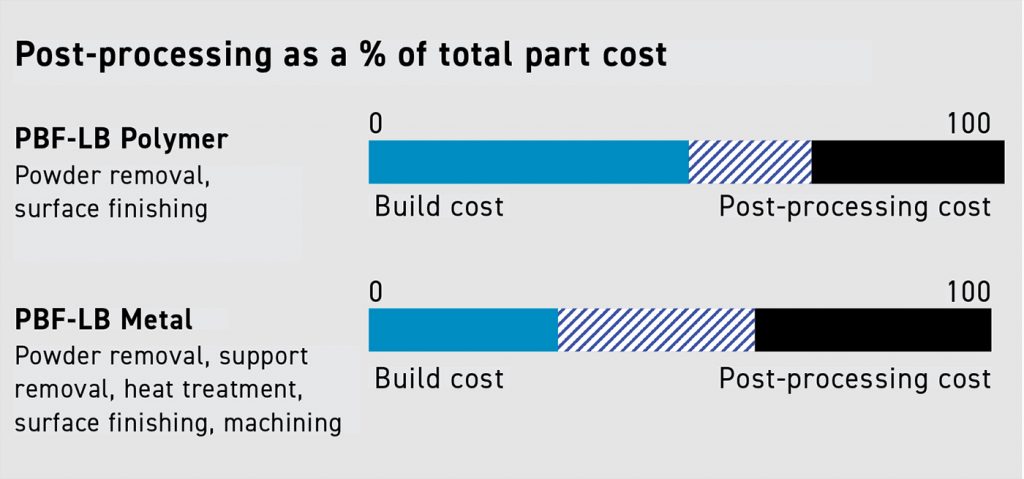
A simple concept can be tarnished by reality. And so it is with Additive Manufacturing. It is widely acknowledged that the downstream processing of AM parts is a headache, and even AM’s most enthusiastic proponents generally underestimate the costs. Famously, the post-processing of AM parts has been called the industry’s ‘dirty little secret.’ Given that post-processing can account for anywhere between 30% and 70% of the total cost of a part, depending upon the design and the AM technology used, post-processing could easily also be referred to as AM’s expensive little secret. The percentage of the total cost attributed to post-processing is generally higher for metal AM than for polymer applications.

The pain of powder removal
This topic has been widely covered, including in this publication, highlighting the necessity of adopting an active powder management strategy for AM, particularly for Powder Bed Fusion. The reasons for action and methodology in powder management are extensive. Reactive materials pose a risk of explosion. Small particles of all powders in the work environment, including airborne particles, are an occupational and health risk for workers in the facility. Powder wastage and high labour costs for handling and removing residues are indirect cost factors that can render many AM applications economically unviable. Failure to remove powder deposits can complicate downstream processes, such as support removal and heat treatment. It can cause a part to be defective or to fail regulatory approval. Lower yield due to unwanted powder residues is very costly. Finally, reusing powder improves the sustainability of the process.
AM machine manufacturers have generally not fully addressed powder-related challenges, leaving third-party suppliers to step in with powder removal solutions of varying sophistication.
Given that the preoccupation with powder removal and management has driven many AM users to adopt some of the solutions available in the market, one would expect that the cumulative industry knowledge and experience on the topic would have gradually mitigated many of the typical powder issues. However, as with many innovative technologies, there is a learning curve. Automated solutions involving vibration, knocking and rotation, if used indiscriminately, can potentially cause damage to parts, and different powders could behave in various ways.

In short, inexperienced use of unsophisticated depowdering methods may not provide solutions to all powder issues. Even the most experienced powder removal solution providers are still learning and continuously improving based on feedback and success stories reported by an expanded user base. The more users continue to adopt these solutions, the greater their appreciation of the challenges will be, and the sooner they will be able to offer a better understanding of the factors that lead to better results.
Beyond the learning curve dynamic just described, there is another less intuitive reason why powder removal is, in some cases, becoming more complicated. The reason lies in the growth of a body of knowledge called Design for Additive Manufacturing (DfAM). Among the leading DfAM advantages, we routinely hear the arguments pertaining to increasing part complexity, lightweight design, and part consolidation. As DfAM gains traction among product developers, designs are increasingly pushed to their limits. With a deeper understanding of AM’s benefits, engineers are increasingly exploring design boundaries, enabling the creation of parts that are beyond the reach of traditional manufacturing.
As DfAM becomes more established, designs are pushed further, making powder removal increasingly complex. While a virtual design can embrace (almost) anything a fervent imagination can dream up, and that virtual design can almost always be additively manufactured, the question then quickly becomes: can the part be post-processed and used as its designers intended? AM designs, it seems, have limits.
In short, the more we deploy the principles of DfAM, the greater the challenge of removing all powder residues. As designs become more complex, it’s essential to accept these limitations, learn from them, and work within them to make the most of what AM can truly offer.
Design for post-processing
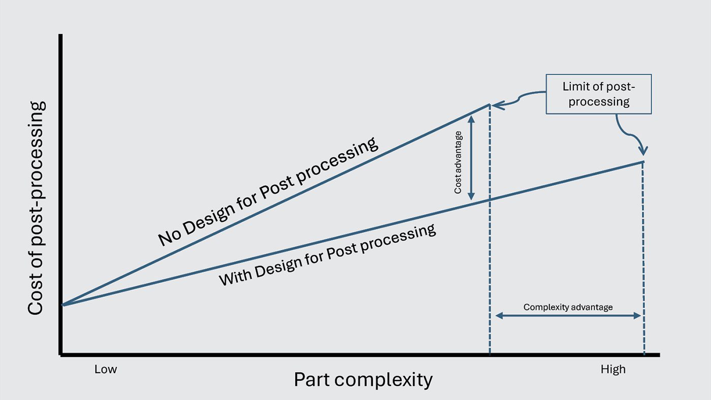
Designing with post-processing in mind can reduce AM costs, particularly for powder removal (Fig. 3). In metal AM, this means that successful product designers need to give thought in advance to several key process limitations. The limitations are a function of the technology being used to manufacture the part, and considerations will be different for metal Binder Jetting than for PBF-LB. Even electron beam PBF will have other considerations than those relevant to PBF-LB due to the different methods of support and powder removal in each process. The takeaway is clear: the more a designer understands the intricacies of the AM process, the better the processing strategy, and the lower the part cost.

Predicting powder behaviour and removal
What if there was a tool that allowed AM operators to simulate and automatically pre-calculate the removal of powder from inside a part made by PBF-LB? In other words, how could the digital twin of a part be used not just for production but also for post-processing? Solukon Maschinenbau GmbH, a pioneer in powder removal technology for Additive Manufacturing, has commercialised an easy-to-use software tool for doing just that. The solution, called SPR-Pathfinder, was first developed in 2018 under the name SiDAM in collaboration with Siemens, which wrote the algorithm that lies at its heart. The driving force behind its development was Christoph Kiener, Principal Key Expert – Functional Product Design & Realization at Siemens. Solukon provided the platform and means for realising the output from the algorithm. SPR-Solukon’s customers and partners tested Pathfinder for several years. Siemens owns the patent rights to the depowdering process, but Solukon finally acquired the source code and has held an exclusive license to the software since 2021. Since then, Solukon has further optimised the software and equipped it with new features.
Solukon’s solution
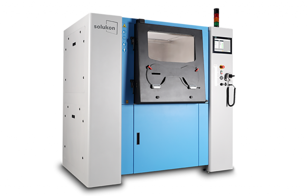
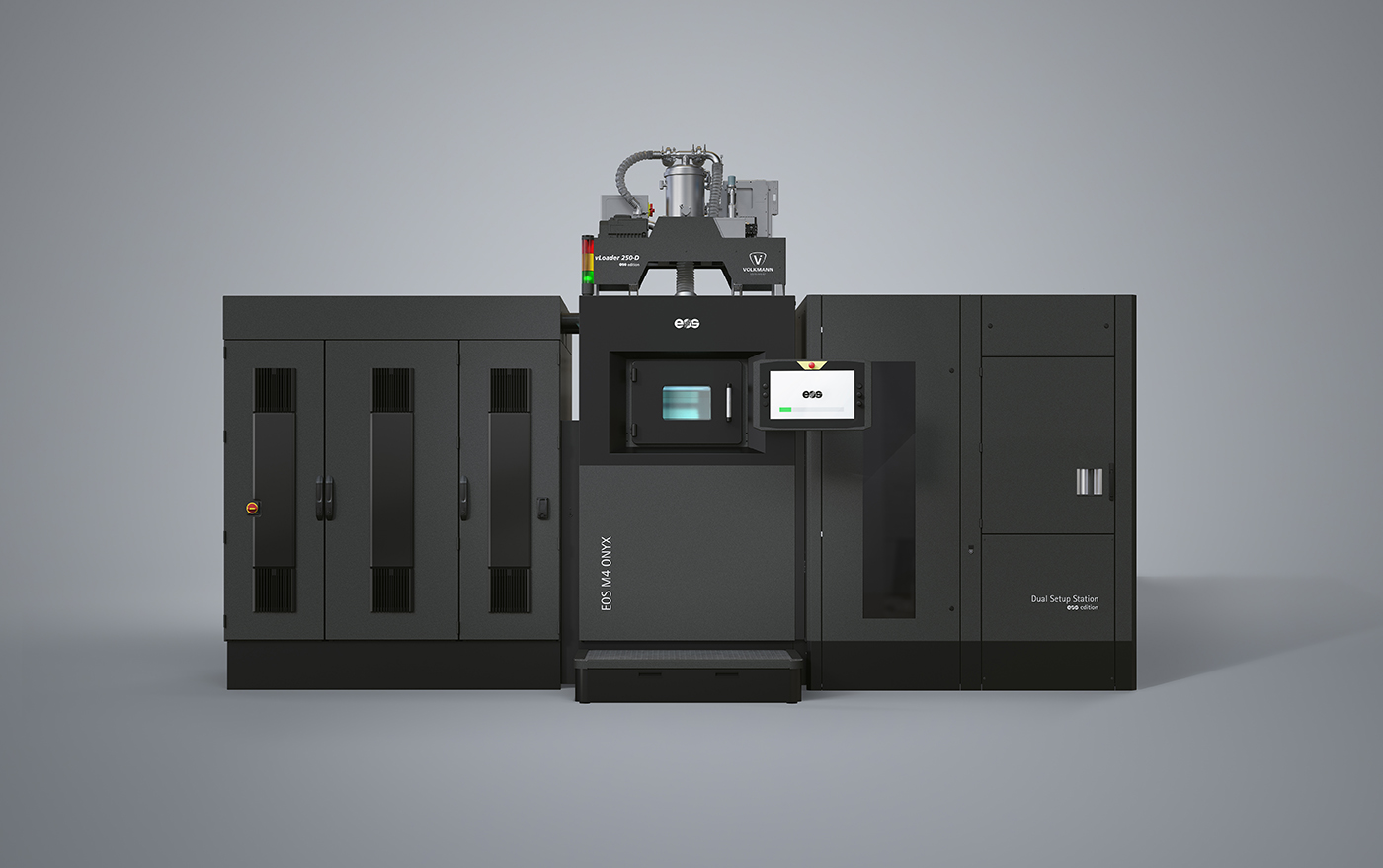
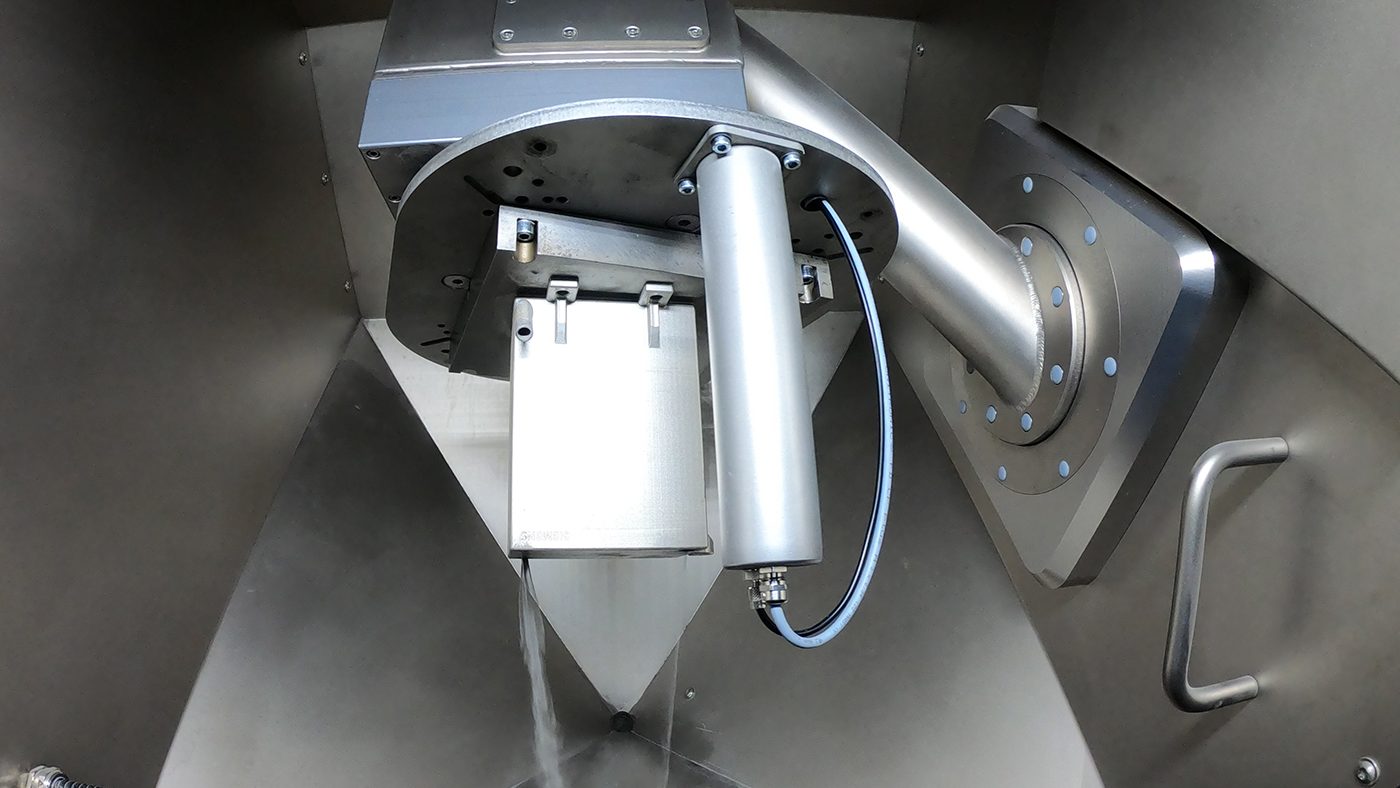
Solukon’s early development of industrial solutions for the depowdering of metal AM parts led to the introduction of the SFM-AT800 in 2015 (Fig. 4), the AM industry’s first automated machine for powder removal. This was a machine developed in response to market demand, with industrial companies turning to Solukon to address the issue of removing powder residues from metal AM build plates.
At the time, the main issue was how to remove the particles from inside complicated support structures. The solution was to automate the depowdering process by placing the build plate and parts into an enclosed environment, frequently inert, and mechanically manipulating it to release hard-to-clean and hard-to-reach residues. The particles were initially agitated or fluidised through pneumatically-driven mechanical vibration, assisted by gravity and the rotation of the build plate through different positions to maximise the powder flow. The company later added high-frequency knocking, which worked in parallel with vibration and was designed to loosen clumps of powder stuck inside the deepest recesses of the build through controlled hammer action. More recently, it has added ultrasonic excitation to its repertoire, which excites the powder particles and readies them for transportation out of the part. This is assisted by gravity through the continuous rotation of the build plate.

How SPR-Pathfinder works
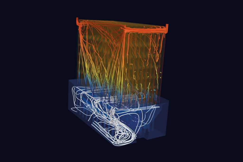
The concept of SPR-Pathfinder is to simulate or pre-calculate the extraction of each particle of powder from inside the additively manufactured parts. The interior of the part could be a channel designed for a functional purpose, such as cooling channels in tooling or complex inner surfaces of a heat exchanger. It could also be an interior space created at the point where a support structure joins the part to the build plate. The steps to operate the software are straightforward:
Loading the CAD file
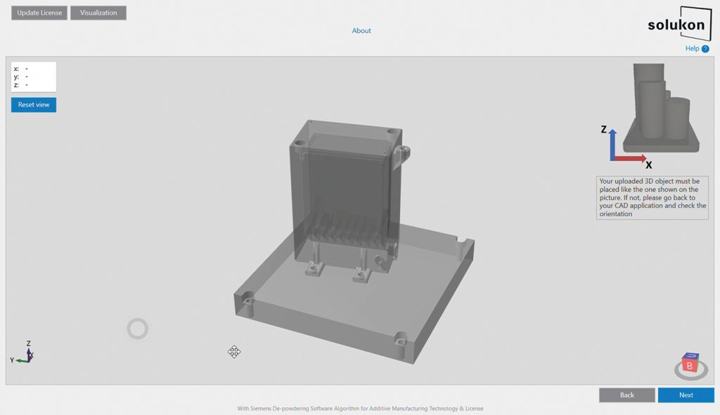
The CAD file of the entire build, including the base plate, is loaded into the Pathfinder software in STL format (Fig. 5). The build can consist of a single part, multiple copies of the same part, or a collection of different parts.
Selecting parameters
Parameters such as the powder used in the build process are selected. Pathfinder is compatible with Solukon depowdering systems, including SFM-AT350, SFM-AT350E, SFM-AT800-S, SFM-AT1000-S, and the recently introduced SFM-AT1500-S. These parameters allow the algorithm to automatically generate a tailored path and cleaning protocol for operating the machine.
Running the software
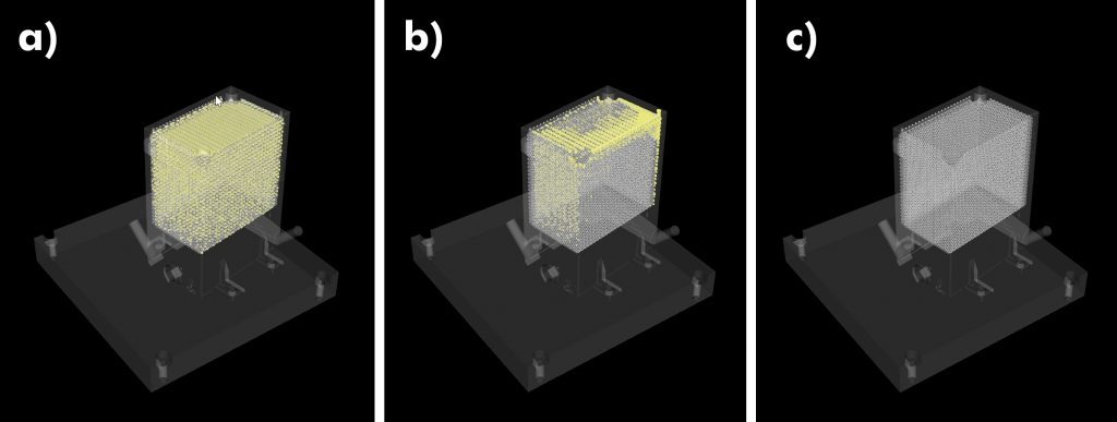
Pathfinder runs to create a machine path and cleaning protocol, optimising powder removal from internal part cavities (Fig. 6). It operates locally on a non-networked computer requiring a minimum of 32 GB of RAM, though more powerful systems will process the simulation faster. The time to run the algorithm varies from a few minutes to several hours, depending on part complexity and the power of the processor.
Identifying powder removal issues
Pathfinder can identify areas where powder removal is not possible due to intricate internal geometries. For instance, a complex heat exchanger may have an opening that is too small for powder to exit. The software highlights these bottlenecks, enabling users to predict cleaning difficulties before a build begins.
Generating the cleaning protocol
After the simulation, the software generates a cleaning protocol that is loaded into the Solukon machine for use in the depowdering cycle. If successful, the protocol ensures all powder is removed in the shortest time possible.
This highlights the need for deeper insights into powder behaviour at a granular level to optimise depowdering. Grain-by-grain simulation ensures even the most complex parts can be cleaned effectively.
Calculation grain-by-grain
The algorithm uses the simulation of the fluidised powder in conjunction with gravity to calculate an exit route, akin to the principle of an emergency evacuation route for a building or a stadium where one must avoid overcrowding and blocking at the exits. This means that it can identify where the powder can flow and creates pathways for the remaining powder to escape from the inner areas of the part.
The algorithm works by assigning a value to each grain of powder that cannot directly reach an opening. It then identifies the powder grain that is furthest from an opening and calculates the optimal path for the Solukon machine to follow in order to guide this grain towards an exit. The powder removal machine uses vibration, with the build plate rotating in 90-degree increments across three dimensions to facilitate movement. However, depending on the part, not all grains of powder can be evacuated due to the constraints of internal channels or other geometrical obstacles within the part.
Smart powder removal
Manually programmed sequences can work for simple components. For more complex parts, a single movement to remove what appears to be a powder choke point inside the part could result in powder getting stuck elsewhere. Manual programming by an operator is unable to see the entirety of the problem from beginning to end. Without full control or visibility, it becomes nearly impossible to ensure that all powder is removed effectively. The software is able to see further and operate quicker than the human brain, in much the same way that software was able to become more proficient at chess than the most talented grandmaster. The movement sequence proposed by the algorithm does not seem comprehensible at first because the software is able to pre-calculate the behaviour of a full chain of future movement sequences using the simulation and the algorithm. The algorithm has long-distance cause-and-effect vision, which the human brain is unable to compete with.
The most profound power of smart simulation of the powder removal process is in the ability to save time in the product development process. Time is money. Even before a product is fully engineered, an inventive engineer with a strong understanding of the PBF-LB process can now use this tool to assess the manufacturability of a part at an early stage, pushing design limits with greater confidence. The cost of design iterations varies depending on the complexity of the product, the industry, and the stage in the development cycle (Fig. 7). Generally, the later an iteration occurs, the more expensive it becomes as factors such as prototyping, testing, tooling, and production adjustments add to the costs.
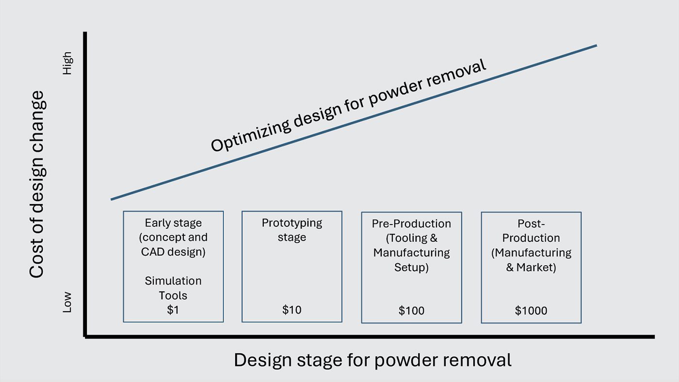
A simulation of powder removal in the AM process is a new digital tool, now available alongside existing simulation tools used at the early design stage, such as finite element analysis and computational fluid dynamics. The ability to make changes based upon a digital analysis at the early design stage is a powerful cost avoidance strategy. This can boost AM feasibility and reduce time-to-part production while also maximising the functionality of design that makes AM so appealing.
Complex designs
Complicated designs are increasingly making their presence felt in the AM media. Many in the industry are familiar with examples of extravagant designs that push the boundaries of what can be achieved. Conflux Technology, an Australian company specialising in complex heat exchangers, is a prime example. One of its signature parts, which has intricate internal channels for optimal heat exchange, was featured on the cover of Metal AM magazine’s Spring 2019 issue. The case for AM-produced heat exchangers lies in their ability to offer superior performance due to the increased surface area provided by their complex designs. Leap71, based in Dubai, is another innovative design company whose advanced creations frequently adorn the pages of industry publications. A notable example is its aerospike engine, which includes numerous complex channels. AM is justified by its ability to create these channels, which are either challenging or impossible to achieve using traditional methods. A category in its own right, though perhaps less dramatic than the examples mentioned above, is of course tooling with internal cooling channels.
Case study: chemical reactor in a box
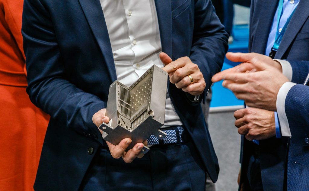
Chemical plants today are large, complex operations with multiple pipes and connections. A collaborative project titled 3D-PROCESS (an acronym for Disruptive Digital Design – Printed Reactors for the Optimization of Chemical processes through Energy Savings and Sustainability) involved several German organisations and was supported by funding from the German government. The project aimed to develop alternative processes for the sustainable and energy-efficient manufacture of chemicals. A team of researchers from Siemens, Evonik, INERATEC and the Karlsruhe Institute of Technology developed a shoebox-sized, additively manufactured chemical reactor integrated into a scalable unit made as a single piece (Figs. 8, 9). The highly complex design can mix chemicals and conduct heat, avoiding energy-hungry chillers. The unit can be scaled up, starting from a model that processes one litre all the way to a machine capable of handling 500 litres. The innovation was recognised at Formnext 2024 with a design award.
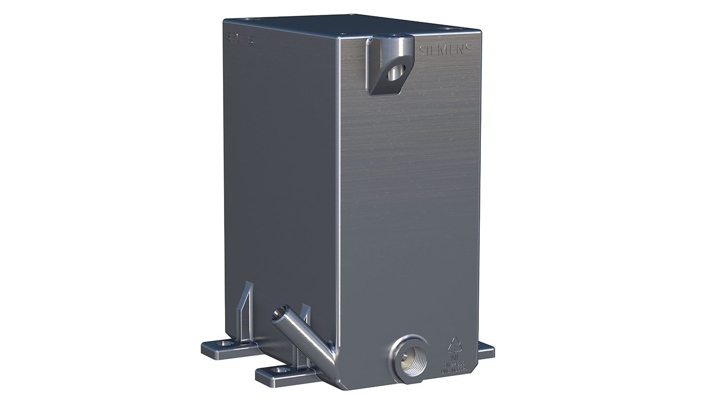
The complex internal structure of this corrosion-resistant alloy part presented a substantial challenge to manufacture. Without AM, it is doubtful that the part could have been made at all. Given the complexity, product designers were faced with a challenge: how to maximise the complex design without affecting the ability to remove the unfused powder from deep inside the part. The designers ran the part through the Pathfinder algorithm (Fig. 6), which proposed a machine path for the successful cleaning of the part, which was then depowdered inside a Solukon machine after the build (Fig. 10).
Case study: thrust combustion chamber
Sòphia High Tech is an industrial research and development organisation based in Somma Vesuviana, Italy. It specialises in AM for the aerospace industry. Sòphia developed and built a lightweight one-piece regeneratively-cooled thrust chamber assembly (TCA) for liquid rocket engines. The conventional process for manufacturing TCAs involves separately constructing the injector, main combustion chamber, and nozzle, which are then assembled and welded together.
Sòphia‘s engineers were able to streamline this process by producing a single-piece TCA using advanced Additive Manufacturing technologies (Fig. 11). The design produced an innovative part with a complex interior structure. The interior channels with rectangular sections were 1 mm in height 2-5 mm in length, with the total channel length being 500 mm. Complete depowdering of the inside of the structure is necessary for success.
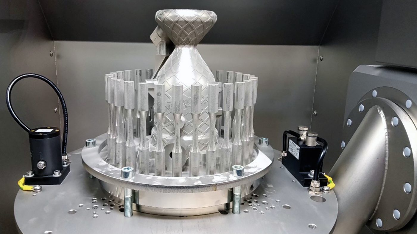
Sòphia is an experienced developer of complex parts and has extensively used automated depowdering systems. The challenge in this case was how to programme the automated system to release the most stubborn powders from the complicated interior design. For this, they ran the Pathfinder algorithm, which automatically produced the cleaning cycle programme. It generated a protocol with 216 separate steps, which ran on a Solukon AT350 in a 40 minute cycle. The cycle was run twice as a precaution to ensure complete depowdering. The part was produced in Inconel 718 on a TRUMPF TruPrint 3000 with a build plate of Ø 300 x 270 mm.
What have we learned?
Metal AM parts are becoming more complex. If they are too intricate and produced using PBF-LB, it may be geometrically impossible to remove the powder from inside the structure.
Building a complex part in a single piece has advantages in design, function and manufacturability. However, failure to remove all of the powder can impact the part’s function or regulatory approval. Identifying this issue early reduces mitigation costs, typically requiring only minor design tweaks. Modelling the powder removal process based on the digital twin is, therefore, the cheapest way to understand whether a part design is viable from the perspective of powder removal.
The inability or difficulty of removing powder would usually require redesign and, in some cases, necessitate building the part in separate pieces to facilitate powder removal. This would involve a manufacturing process to join multiple parts by welding or brazing, meaning higher labour costs, extended production time, and potential issues at the joins.
Even if automated depowdering through mechanical agitation or rotation could, in principle, be deployed to solve the issue, programming the device is time-consuming and would result in a less efficient powder removal cycle.
It is gratifying to know that deploying digital analytical tools to solve physical problems through the use of powerful yet relatively cheap computing power is a reality in the AM industry. We have become accustomed to using design, diagnostic and simulation tools such as CAD, CAE, FEA, and CFD that can give us a high-level understanding of the physical behaviour of a real product even before the first layer has been printed. To this illustrious parade of engineering acronyms, we can now add another advanced digital solution, this one to solve a problem endemic to Additive Manufacturing. Perhaps we could call it Powder Mobility Analysis (PMA) or Depowdering Feasibility Analysis (DFA). Regardless of how we define them, smart tools – such as those embedded in the Pathfinder algorithm – serve both to diagnose problems and to execute remediation. They are yet another example of how advanced manufacturing continues to integrate the digital and the physical. We live in interesting manufacturing times.
Author
Joseph Kowen
Joseph is an industry analyst and consultant who has been involved in Additive Manufacturing since 1999. He is an Associate Consultant at Wohlers Associates, part of ASTM International’s AM Center of Excellence.
www.linkedin.com/in/joseph-kowen-a5129b3/
Contact
Solukon Maschinenbau GmbH
Aulzhausener Str. 14
86165 Augsburg, Germany
www.solukon.de
[email protected]

LAST MONTH’S MOST-READ ARTICLES