


Velo3D: How a ‘support-free’ Laser Powder Bed Fusion process could remove roadblocks to serial Additive Manufacturing
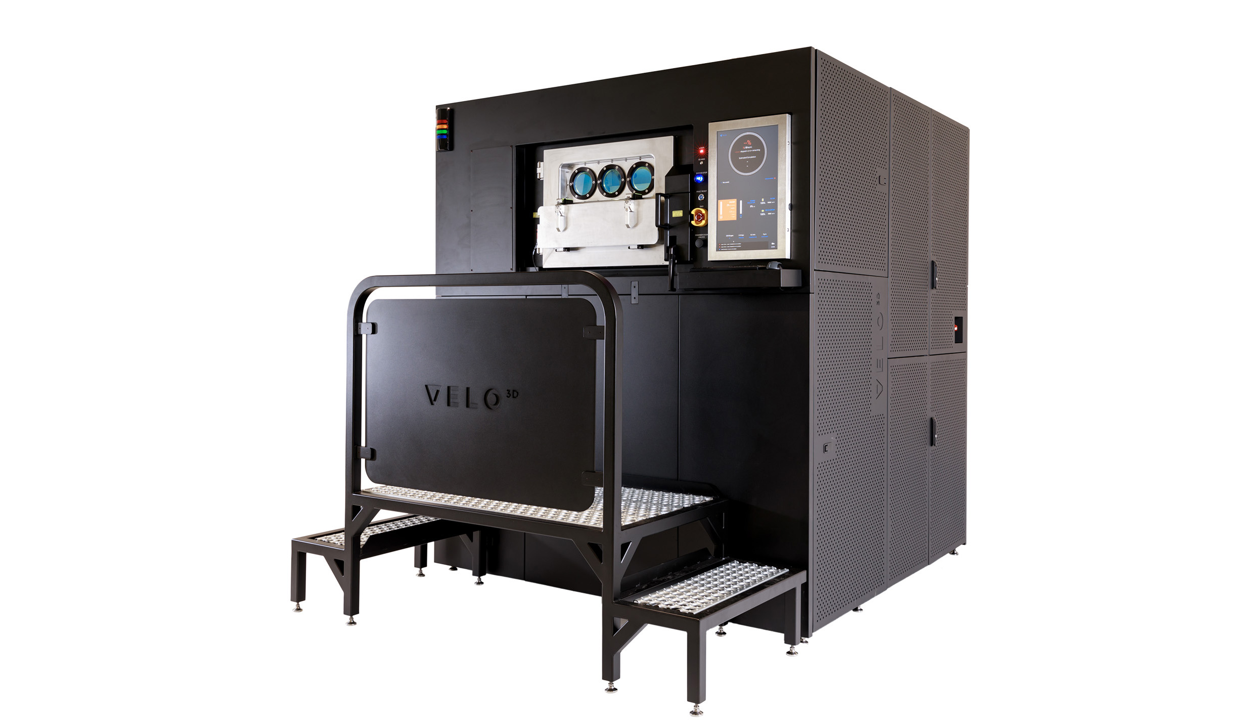
With its Sapphire machine and Flow build preparation software capable of highly-controlled, virtually support-free Additive Manufacturing, Velo3D is pushing the limits of what is possible with Laser Powder Bed Fusion (L-PBF). Since launching its first machine in 2018, the California-based company has seen success with a range of highly complex parts which would challenge even the most experienced AM engineer. In this article, Zach Murphree, Velo3D’s Vice President of Technical Partnerships, explains the key factors which set the company’s process apart from the wider AM market. [First published in Metal AM Vol. 5 No. 3, Autumn 2019 | 10 minute read | View on Issuu | Download PDF]

There is a misconception in the Additive Manufacturing world that Zach Murphree, Vice President of Technical Partnerships at Velo3D, is on a mission to clear up. The scaffold-like structures that everyone in the industry refers to as ‘supports’ are in reality, he says, anchors. They are used to keep the layers of fused metal powder from peeling up and away from the previously-built layers or build plate below, rather than to support the layers above and prevent their collapse.

“The term ‘support’ is really a holdover from plastic printing,” he told Metal AM magazine. “Here, you need support structures because you’re fighting gravity, and the part would distort or even collapse without them. With L-PBF, however, you’re fighting the metal’s tendency to curl upwards, especially at angles of 45˚ or less. If you don’t anchor these surfaces down, your recoater blade will eventually smash into them, damaging the workpiece, the blade, and possibly even the machine.”
This ‘taco shell effect’ is not unlike what happens when two sheets of unrestrained metal are butt-welded together. In AM, however, any unrestrained metal can lead to build failures, hence the need for temporary structures that later require costly, labour-intensive machining and grinding to remove. And it is this secondary post-processing – more than any other manufacturing constraint – that has been the thorn in metal powder bed AM’s side since its very inception.
Whether they are supports or anchors, Murphree and his colleagues at Velo3D aim to reduce the reliance on them in metal AM. Doing so will, it is expected, allow manufacturers to skip the lion’s share of post-processing; they will no longer need to use valuable time ‘taking down the scaffolding’ post-build. Build plates could also, the company believes, become a thing of the past, if parts were to be made free to ‘float’ within a fully-utilised build chamber. Most importantly, reducing support structures could allow the realisation of the much-vaunted design freedom associated with AM, which has until now come with many caveats. Geometric constraints might be largely eliminated, as well as worries over warping, part orientation, and wasted support material.

Reaching the goal of support-free AM
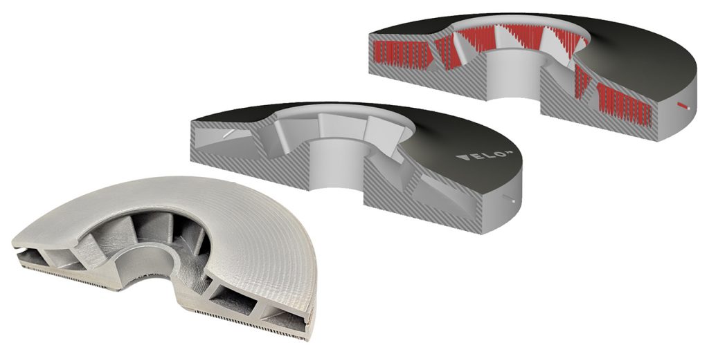
Velo3D isn’t quite there yet, stated Murphree, but it is close. The company’s Sapphire AM system can currently build support-free surfaces at angles lower than 10˚ (often horizontally), as well as structures with large inner diameters that would normally need to be tear-drop shaped to maintain their structural integrity using conventional L-PBF systems (Fig. 2). In addition, Velo3D states that it is often able to build even very complex workpieces ‘right first time’, something that few in the Additive Manufacturing industry can claim.
While Velo3D’s process has some unique features, it, like almost all powder bed AM processes, relies on a bed of finely-atomised metal powder; a pair of lasers; and a gas-filled, oxygen-free chamber. As in the majority of AM processes, parts are built layer by layer, from the bottom up, with a recoater spreading fresh material across the burgeoning workpiece at every step.
Explaining what is different about Velo3D, Murphree stated, “For the most part, our technology is based on a much higher level of process control. Our company founder and several others here have extensive experience in the semiconductor industry, and they have leveraged that experience to develop a far more capable AM machine, one that no others can currently match in terms of beam management, integrated metrology, machine construction, our non-contact recoater design and, especially, the build software. That’s key.”

Infinite control over finite elements
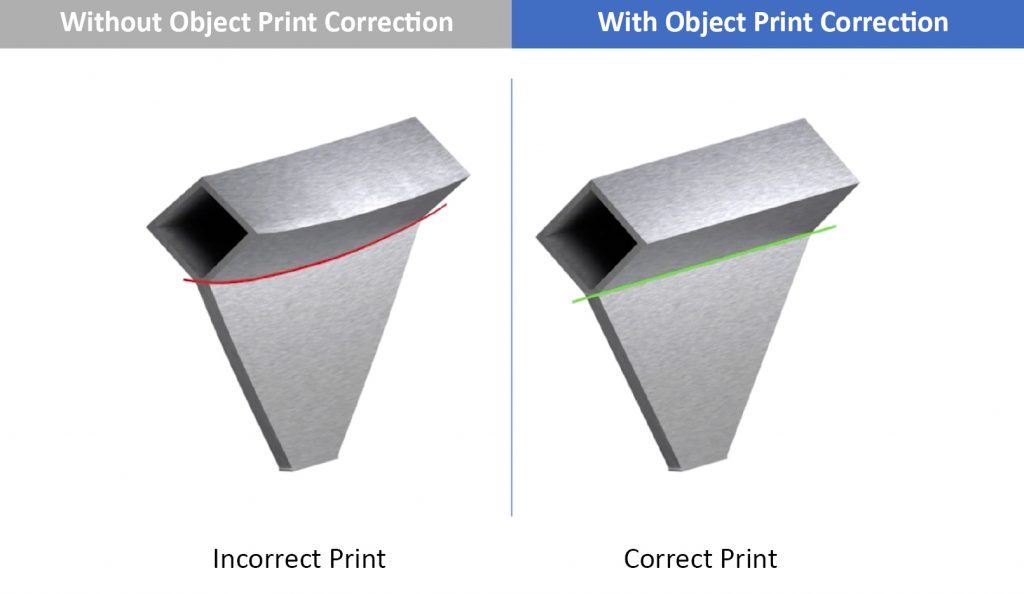
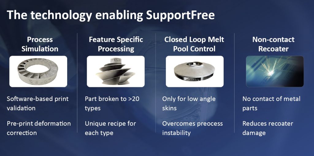
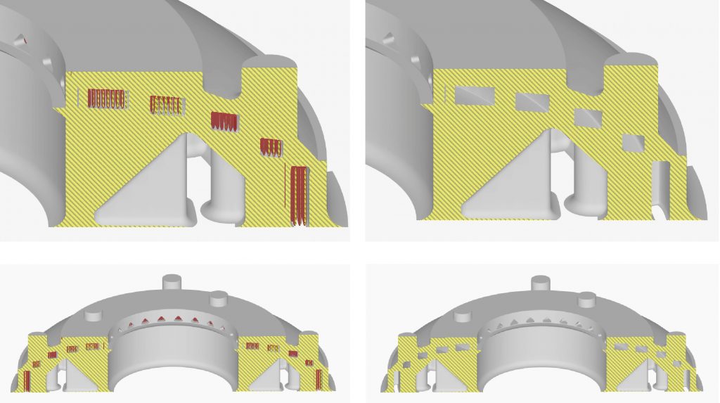
The processing algorithms within Velo3D’s Flow software, Murphree noted, are an order of magnitude more advanced than those used by most AM systems. This software is able to accurately simulate the build in advance; analysing, predicting, and then compensating for potential deformation long before manufacturing begins (Fig. 3). In addition, rather than processing one layer at a time, Flow looks at ‘several tens of layers’ both above and below the current one, detecting part geometry on-the-fly and applying feature-specific routines wherever needed to further optimise the build strategy.
This is somewhat similar to Finite Element Analysis (FEA) software, Murphree stated, which uses implicit modelling to analyse an entire workpiece at once. “If you’re going to build the correct geometry, you need to consider the complete geometry, and focus your efforts on applying the right processes in this larger context,” he says. “This is a big chunk of our ‘first part, good part’ success ratio.”
The computing power needed to achieve this FEA-like functionality would likely have been cost-prohibitive as little as five years ago, but thanks to parallel computing and the use of very efficient software code, Velo3D can solve ‘huge slabs’ of the model simultaneously. This means analysing thermal boundaries all around the melt pool, then applying an optimised mix of laser power, beam positioning, and spot size to fuse the metal without negatively impacting the surrounding area.

Greater accuracy through the elimination of process variables
Even the best build software doesn’t guarantee that the laser will go where you tell it to. Build accuracy may be affected by alignment issues, beam quality and atmospheric conditions within the build chamber. Murphree states that Velo3D has addressed each of these factors in its technology. Using the same attention to detail found in semiconductor fabrication, his team believes that it has reduced or eliminated the process variables common to L-PBF systems (Fig. 4).
This last factor highlights another important difference between Velo3D’s system and others, he says. “For example, we have the ability to align our lasers to within 50 µm or less of one another at every single layer. The result is far greater part quality, with no visible overlap or witness marks where the lasers have traded-off duties. We have a non-contact recoater and enhanced gas flow, both of which serve to improve process stability. We also control the oxygen levels to less than 10 ppm, and often fall below 1 ppm – roughly 1000 times better than the industry’s standard. We’ve found that an oxygen level of even 50 ppm affects the surface tension on the melt pool, and has a dramatic impact on its behaviour.”
Monitoring and control of spot size
Murphree explained that control of spot size in laser powder bed systems is crucial, explaining that even a 10% increase in the diameter of the spot can decrease the amount of applied power at the melt pool exponentially. “Left uncompensated, this can mean 98% material density instead of the 99.9%, fully-dense metals expected by the industry. This might not sound like much, but it’s actually a huge difference, especially for those producing aerospace and power generation components. The metal’s mechanical properties can deteriorate markedly as well, with unacceptable levels of porosity as well as lack of fusion between layers, a failure mode that’s quite difficult to detect.”
Velo3D manages these variables and more, he says, through gas-tight, thermally-stable machine architecture and continuous process monitoring via a host of onboard sensors. Aside from the basics such as chamber temperatures and oxygen levels, data on thermal lensing, scan-field distortion, and other indicators of optical health – what he calls the heart of any AM system – are also collected, providing complete in-process history of all part builds as well as an opportunity to further refine system performance. “That’s been an important goal for us from the very beginning and to learn from all this data,” stated Murphree.
Case study: KW Micropower Inc.
Recently, Velo3D collaborated with Florida’s KW Micropower Inc. to develop a unique diffuser housing for production by metal Additive Manufacturing (Figs. 5, 6). Enrique Enriquez, founder and President of the business, stated, “I’d talked to every AM company I could find and they all told me the same thing: we can’t build your part. Fortunately, at the last IMTS show, a friend suggested I stop by the Velo3D booth – and that changed everything.”
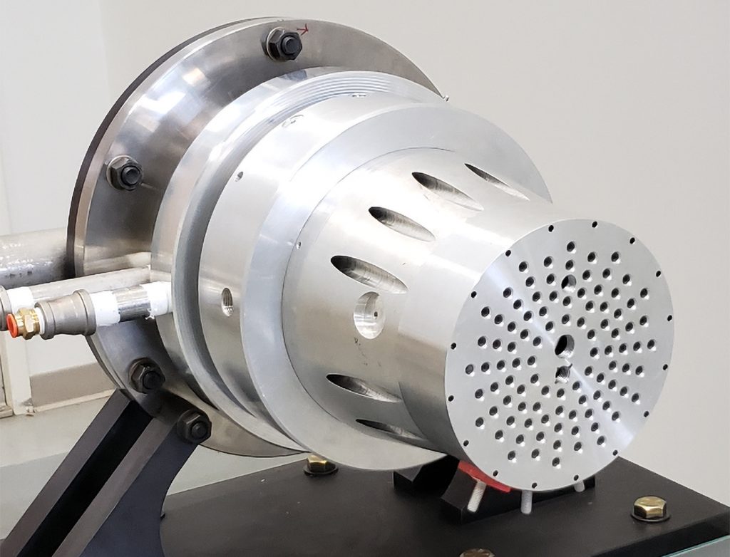
Enrique’s diffuser housing is a Ti6Al4V disk measuring approximately 25 cm in diameter by 10 cm high, and contains a complex series of internal, low-angle passageways for gas flow. It is a critical component in a miniature power generator that he’s been working on for the past four years, and he will soon be exploring serial production of the device.
When finding a manufacturer who could produce the part, the hurdle was the internal channels and the fact that there was no way to remove the hundreds of tiny supports required by other metal powder bed printers (Fig. 7). As stated earlier, Velo3D’s process is nearly support-free. In addition, due to the Sapphire’s high level of process control, Murphree had few concerns over building the part in titanium, a difficult-to-process and reactive alloy. He was also able to use the company’s Flow software to improve Enriquez’s original design, reducing its weight by 37% while improving its flow characteristics. According to Murphree, the part was built correctly on the first attempt.
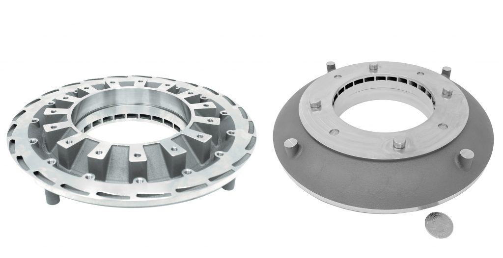
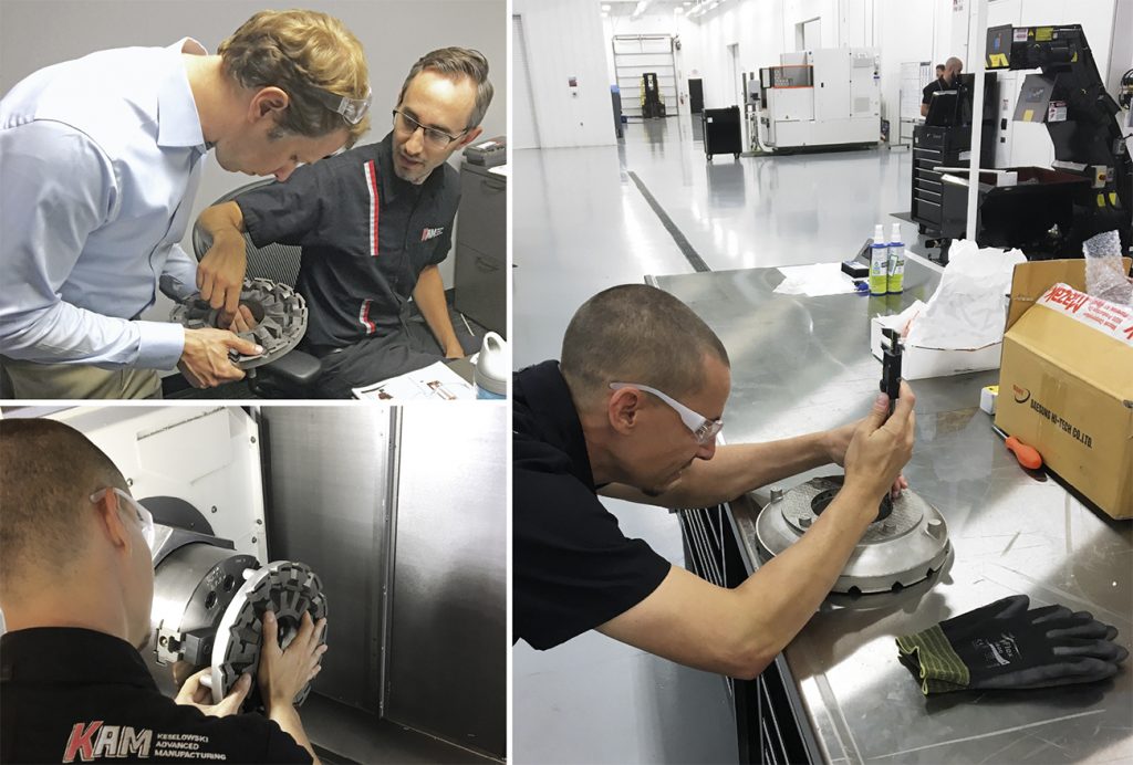
As with almost all additively manufactured parts, the component still required some post-processing following the build process. Murphree contacted Jim Thompson, Director of Operations for Keselowski Advanced Manufacturing (KAM) in Statesville, North Carolina, USA, to inquire about finish machining several of the diffuser housing’s close-tolerance features. KAM has extensive experience in the fields of both additive and subtractive manufacturing and is quite familiar with Ti6Al4V.
The diffuser housing was machined on the KAM shop’s Mazak I300S 7-axis machining centre, allowing Thompson to complete the part in one operation. KAM also built an aluminium replica of the part on one of its existing metal powder bed AM systems to test the impact of Velo3D’s support-free process on its post-processing requirements (Fig. 8). Following testing, Thompson stated, “With the Velo3D part, the internal channels were clean – no supports, just like Zach told me. In contrast, the part printed on our legacy equipment, as we anticipated, required us to spend approximately forty hours on support removal and clean-up of the surfaces afterwards. There was none of that with the Velo3D part, nor were there any of the usual problems with supports breaking loose and getting caught between the cutter and workpiece, possibly damaging both.”
KAM’s President, John Murray, added another key point: “Because the Sapphire is inherently more accurate than competing technologies, parts come out of the machine closer to net shape. This means you’ll need less machining time to finish them. And as anyone who owns a metal printer knows, the raw material itself is not inexpensive. Comparing the Velo3D part with the one that we printed, I figure you could save an additional 10–30% on material costs, plus the additional build time necessary to lay down all that metal, only to machine it away later.”
Conclusion
Following the successful build and finishing of his part, a pleased Enrique Enriquez stated, “The results have been totally amazing. We’ve logged thousands of test hours with the generator, and hope to start sending prototypes out next year for evaluation. A device this small is very sensitive to what they call parasitic losses due to friction and imbalance; in order to compensate for that, you need to find ways of making everything more efficient. That’s what Velo3D brought to the table. Because of their capabilities, we’re now able to do some amazing things that were never expected out of a generator this small. Their technology has opened up a world of opportunities for me.”
Contact
Joyce Yeung
Director of Marketing
Velo3D
[email protected]
www.velo3D.com
LAST MONTH’S MOST-READ ARTICLES


