


Smart sensor-integrated parts by AM: A look at a novel possibility with industrial applications
Additive Manufacturing processes offer a high degree of design freedom. The Laser Beam Powder Bed Fusion of metals (PBF-LB/M), in particular, has established itself for series applications of complex-shaped parts in numerous industries. In this article, Prof Dr-Ing Christian Seidel considers the next major step in PBF-LB, which could offer designers unknown potential: the production of sensor-integrated AM parts. Methods and solutions for the manufacturing of sensor-integrated AM parts are presented and industry-relevant case studies showcased, illustrating the potential offered by sensor-integrated ‘smart parts.' [First published in Metal AM Vol. 8 No. 4, Winter 2022 | 20 minute read | View on Issuu | Download PDF]
Product developers appreciate Additive Manufacturing because it offers a high degree of design freedom. For instance, the topology of a component in the force flow can be optimised according to the loads occurring, and the result can be ‘printed’ more or less directly. A well-known application for this capability is in aircraft brackets made of titanium alloys. The possibility of function integration has also been exploited in numerous industries, since, with AM, solid-state joints or porous structures can be manufactured in a targeted manner.
On top of these applications, several examples can be seen where sensors were implemented manually by operators during the build process. The resulting sensor-integrated parts are also referred to as ‘smart parts.’ Additive Manufacturing technologies are particularly suitable for such parts, since the principle of layer-on-layer manufacturing allows sensors to be integrated close to the desired measuring point, even in parts with complex geometries.

Current fast-growing digital trends, such as condition monitoring and predictive maintenance, are increasing the pressure on Additive Manufacturing technologies to be able to produce smart parts whose condition can be monitored by sensors. In this way, maintenance intervals can be minimised and components proactively replaced, even before their technical failure. To realise the Additive Manufacturing of such sensor-integrated smart parts, two main challenges must be solved:
- The build process needs to be modified to allow for sensor handling
- The sensors need to be able to withstand the thermal loads that occur during the build, and must be fully functional downstream of the integration
Possibilities for integrating sensors during the Powder Bed Fusion process
![Fig. 2 Comparison of different methods for integrating sensors in Powder Bed Fusion technologies (Courtesy Binder et al. [1])](http://www.metal-am.com/wp-content/uploads/sites/4/2022/12/fig-02-1-1024x417.jpg)
Following Binder, et al. [1], three different approaches are known for integrating sensors during PBF-LB (Fig. 2):
- Manual insertion of sensors
- Automated insertion of sensors
- Direct manufacturing of sensors, for example by means of a multi-material mechanism
Each approach has its strengths and weaknesses. Manual sensor integration has disadvantages compared to an automated solution, as the integration times are much higher and operator expertise is needed. In addition, loss of part quality and reproducibility must be avoided, which is a challenge because, typically, the inert gas atmosphere must be interrupted to manually insert the sensors into the part. However, no additional machine components are needed for the manual process.
The most elegant way to fabricate a smart part is to build the sensors via PBF-LB within the build chamber. Using this method, no additional sensors need to be handled. One way this can be achieved is by processing multiple materials within a single build. However, this concept still has limited maturity, and more research is required before it can be tested and determined to what extent direct sensor production is possible on an industrial scale.

Fig. 3 illustrates an automated sensor integration process. The images were captured in the laboratory of Fraunhofer IGCV in Augsburg, Germany. To achieve the automated sensor integration, an AconityOne metal PBF-LB machine (Aconity3D GmbH, Herzogenrath, Germany) was modified to allow for a pick-and-place unit to be used within the build chamber; this additional hardware was integrated into the AconityOne and can also be controlled by the machine software. The layer-on-layer build job can be interrupted in a defined layer (steps 2-7 in Fig. 3) to allow for automated sensor integration without losing the protective gas atmosphere.
![Fig. 3 Automated sensor integration by utilising a vacuum gripper, following Binder et al. [1]: Step 1: building cavity geometry, 2 and 3: vacuum cleaning of cavity, 4: pick sensor from sensor magazine inside the build chamber, 5 and 6: place sensor inside the cleaned cavity, 7: application of a new powder layer, filling the cavity with the sensor, completed, 8: continuation of the main build](http://www.metal-am.com/wp-content/uploads/sites/4/2022/12/fig-03-1.jpg)
Integration of Weldable Strain Gauges – pilot testing and case study of a probe rake
Weldable Strain gauges (WSG) are used to monitor mechanical force, such as compression and strain. Typically, WSGs are fixed to the surface of the part by glued or weld-on bonding. This conventional approach has crucial disadvantages: a WSG mounted on the component surface does not provide any information about the forces inside of the component and is exposed to the surrounding environmental influences.
Due to the layer-on-layer build method of Additive Manufacturing parts, sensors can be integrated almost anywhere within the part; therefore, these drawbacks are overcome. But the adhesive bonding typically used presents challenges for many metal Additive Manufacturing processes due to their high process temperatures and the curing times of the used glues. Therefore, Binder et al. [2] described a weld-on method for WSG integration where the firm fusion for force transmission is created by applying weld seams between the sensor (WSG) and the AM component. Since welding is the basic principle for PBF-LB, no additional laser source is needed for the spot welding required to connect the WSG with the part.

For handling the WSGs, Binder et al. [2] used manual integration, as the system shown in Fig. 3 is not currently optimised for the handling of flexible components such as WSGs. Fig. 4 (left) shows the as-built tensile test rod with the integrated strain gauge. As can be seen in the measured data (Fig. 4, right), the accuracy of the WSG is limited until a strain of 0.027%. Starting at 0.027% strain, load detection of the as-built smart tensile rod, compared to the value of the tensile testing machine, is accurate with ca. +/- 5% deviation in measured stress values.
![Fig. 4 Weldable strain gauge (WSG) tensile test: (a) Schematic view of the tensile rod with integrated WSG; (b) Associated graph: the tensile testing machine is shown in dotted line, the 5 times repeated answers of the WSGs in different shades of grey. (Source Binder et al. [2])](http://www.metal-am.com/wp-content/uploads/sites/4/2022/12/fig-04-1-1024x563.jpg)
After having proven that the integration of WSGs is possible for basic geometries such as a tensile rod, a case study with a gas flow probe was performed. Thereby, a ‘probe rake’ provided by Vectoflow GmbH was redesigned and additively manufactured as a smart part. The said component is usually manufactured by the company Vectoflow, without integrated sensors, using PBF-LB. Its function is to measure locally occurring gas flows in a streaming field (e.g., within an aero engine).
Due to the surrounding flows, vibrations can also occur on the measurement system, which cannot be detected so far. However, vibration data is an important parameter for both the design of the measurement system and for more detailed testing and analysis of flow fields.

Fig. 5 shows the ‘smart version’ of the probe rake manufactured out of nickel-base alloy IN718. This part was built on an SLM®125 system (SLM Solutions AG, Lübeck, Germany) at Vectoflow GmbH. For the integration of the WSG, the parameter constellation from pilot testing with the tensile rod was used (laser power PL = 150 W, scan speed vs = 200 mm/s, weld width 0.18 mm). Since the WSG requires a cable connection, a cable duct (X-Y plane) was provided, through which the measuring cables of the sensor component are guided out of the probe rake via the carrier plate.
![Fig. 5 Additive Manufacturing of smart probe rakes with integrated Weldable Strain Gauges (WSGs) to determine occurring vibrations and forces. Case study performed by Fraunhofer IGCV together with Vectoflow GmbH (Source Binder et al. [1])](http://www.metal-am.com/wp-content/uploads/sites/4/2022/12/fig-05-1-1024x510.jpg)
To evaluate the proper operation of the smart flow rake, a vibration test of the system was performed. The test setup is shown in Fig. 6. An MX840B amplifier was used with a quarter-bridge circuit (350 ohm) at a sampling frequency of 1,200 Hz. A defined frequency of 350 Hz was applied to the flow rake in accordance with the US military standard MIL STD 810 H via a turbine vibrator. The flow rake was then subjected to a test with a defined frequency of 350 Hz. The correctness of the vibration behaviour was ensured by an externally applied Fibre Bragg Grating (FBG) sensor. In this state, the vibrations detected by the strain gauge (WSG) were evaluated and compared with those of the FBG. Fig. 6 shows that the power maxima occurred equally at 350 Hz. This confirms the correct operation of the concept.
![Fig. 6 Test setup for the additively manufactured sensor-integrated smart flow rake, focus: determining the accuracy of measurements in terms of vibration and spectral power densities under an applied vibration of 350 Hz (Source Binder et al. [1])](http://www.metal-am.com/wp-content/uploads/sites/4/2022/12/fig-06-1-1024x415.jpg)
Case study: RFID-sensor-monitored gear wheel
The probe rake case study showed that implementing sensors with cables is challenging for automation. For that reason, the integration of the WSG was done manually to ease cable handling inside the powder bed. In this case study, radio-frequency identification (RFID)-based sensors are used to monitor a gear wheel. As RFID-sensors do not typically require cables, they are suitable for both manual and automated integration, for example by means of a vacuum gripper. However, several challenges remain, such as: ensuring proper operation and data transfer of RFID sensors in an electromagnetically shielded metal environment; enabling battery-free operation; and offering sufficient protection against thermal load during the manufacturing process.
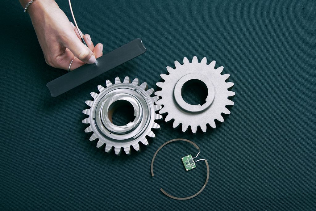
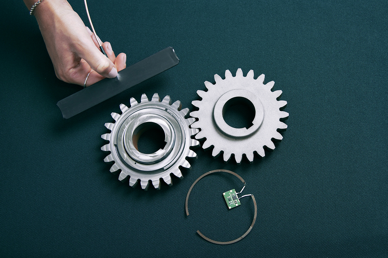
By overcoming these challenges, it will be possible to draw conclusions about the lubrication or damage condition of a gear through vibration analysis, but also to record eigen frequencies of the system or the rotation speed of the gear. Within this case study, a straight-toothed type C gear with a tip diameter of 118 mm, a bore diameter of 40 mm, twenty-four teeth and a normal modulus of 4.5 was investigated. The gear is a typical gear test geometry and is designed for a load of 250 Nm at 3000 rpm, Fig. 7.
![Fig. 7 Illustration of the used test gear with a diameter of 118 mm with a focus on the concept of the external antenna in combination with the internal sensor cavity (Source Binder et al. [2])](http://www.metal-am.com/wp-content/uploads/sites/4/2022/12/fig-07-1-1024x477.jpg)
Of the RFID technologies, UHF (ultra-high frequency, 868 MHz) provides a high data rate and long reading range (up to 12 m) compared to LF (low frequency, 125 kHz) and HF (high-frequency, 13.56 MHz) with a reading range of few centimetres, making it the most suitable technology for the project. The UHF RFID technology is widespread, so that a large selection of components and infrastructure is available for a corresponding system.
However, as it is known that electromagnetic waves are strongly shielded by metallic components and, compared to LF technologies, which use inductive coupling, are not able to penetrate metal, this is a major obstacle. Therefore, an antenna located on the outside of the gear wheel is to be combined with a well-protected sensor unit positioned inside the gear wheel. In this way, negative shielding effects on the electromagnetic waves can be reduced, and the more powerful UHF technology (longer range, faster transmission rate) can be used.
A dipole antenna was designed on the outside of the gear which matches the circular shape of the part. To be able to measure the acceleration data inside the gear and to protect the electronic printed circuit board (PCB) from environmental influences, such as moisture or oil, a cavity was designed for the sensor integration. The following components were used and positioned inside the cavity (width: 20 mm, depth: 3.5 mm) to implement the concept:
- UF Reader PulsarMX UHF Mid-Range Reader (power transmission: 27 dBm, 500 mW)
- KX122 Tri-Axis Accelerometer (Kionix)
- UHF RFID IC: Rocky100 (860-960 MHz, ISO18000-6 type C compliant, operating temperature between – 45 and + 85°C)
To ensure sufficient protection against thermal load during the manufacturing process, the cavity design foresees a triangle shaped closing of the cavity, Fig. 8. As with the case study on the probe rake using WSG, the electrical connection of the PCB was made using the laser in the PBF-LB machine as a spot welder.
![Fig. 8 Sectional view through the cavity of the gear wheel during the build-up process (Source Binder et al. [2])](http://www.metal-am.com/wp-content/uploads/sites/4/2022/12/fig-08-1-1024x614.jpg)
After the gear wheel was additively manufactured, and the powder removed, contour conforming wire electrical discharge machining was used to separate part and build plate, and the foreseen cavities were filled with an insulating material by casting. As part of the validation process, a CT scan verified that the electrical contact between the antenna and the RFID transponder was successful and that the position of the integrated circuit board was maintained even after casting and curing of the insulation matrix.
Subsequently, the function of the sensor-monitored gear was ensured by checking the readability of the data. At a distance of 1 cm between the reader and the gear wheel, the data can be read out reliably, even when the gear wheel is rotating. The gear wheel was rotated at approx. 360°/minute and the resulting wirelessly transmitted values were read out.
In summary, the gear wheel case study demonstrated how a smart gear wheel can be produced by designing a UHF RFID antenna and extending the standard Additive Manufacturing process. This approach offers great potential for industrial applications and, at the same time, hardly influences build time and manufacturing costs. Nevertheless, specific challenges remain to be investigated on a case-by-case basis before industrial adoption.
Post-heat treatment:
Current PCB can typically not withstand thermal loads of over 600°C. This can become a challenge if, for example, stress relief annealing, or other material-specific heat treatment routines are required.
Data transmission rate:
To enable vibration monitoring of the component in the future, it is beneficial to record and transmit vibrations at a higher frequency. While the system presented in this work is capable of transmitting data at a frequency of 1–2 Hz, for vibration measurement it is desirable to be able to resolve vibrations at, for example, > 1,000 Hz, otherwise relevant high-frequency vibration changes might not be resolved. Initial approaches for overcoming this challenge are already available but need to be verified for the specific industrial application.
Reading distance:
The maximum readout range within this case study was less than expected at ~1 cm instead of the desired range of several meters. This is probably due to the electromagnetic field influencing the metal environment and the rather low achievable gain of the antenna. Specific investigations on antenna design and performance are recommended.
Conclusion
The layer-on-layer build-up concept of Additive Manufacturing enables the production of complex geometries. In addition, process interruptions during the build process can allow sensors to be inserted into components, turning them into so-called ‘smart parts.’ Compared to manufacturing technologies such as milling, casting or forming, there are hardly any restrictions regarding the positioning of the sensors, which allows excellent possibilities for applications such as condition monitoring.
This paper outlined three possible methods for sensor integration:
- Manual integration
- Automated integration
- Direct Additive Manufacturing of sensors in the part (e.g., through multi-material processing)
Today, manual integration is especially beneficial when sensors with cables, such as the WSGs in this article, must be used in powder bed-based processes. Today, these form-labile components can’t be inserted automatically in a process-safe manner. RFID technology-based sensors are form-stable and can be handled well using, for example, vacuum gripping technology. Therefore, they can be inserted manually or automatically using the approach described within this contribution. However, to ensure proper function during operation, it must be ensured that the measurement signals of the RFID sensors can pass through the metal component. In the example shown, this was achieved by means of an additively manufactured antenna.
The advantage of automated sensor integration is that the inert gas atmosphere in the build chamber does not have to be interrupted and, in general, the insertion process takes only a few seconds. This means that producing ‘smart parts’ extends the machine operating time only marginally, whereas the functionality of the built components can be significantly increased.
It can, therefore, be assumed that sensor-integrated and additively manufactured components hold great potential that has yet to be tapped at present. With the current state of knowledge, this potential can be exploited. Since there are currently no commercial machines available on the market that enable the AM of sensor-integrated components, targeted collaboration between researchers, machine manufacturers and users will be required in the coming years to leverage this potential.
Acknowledgement
The author expresses his sincere thanks to the Free State of Bavaria and its Bavarian Ministry of Economic Affairs, Regional Development and Energy for funding the MULTIMATERIAL-Zentrum Augsburg (Multi-material Centre Augsburg). Furthermore, the author thanks Maximilian Binder, Thomas Bareth and Veronika Stapff for their valuable contributions.
References
[1] Binder, M, Dirnhofer, C, Kindermann, P, Horn, M, Schmitt, M, Anstaett, C, Schlick G, Seidel, C, Reinhart, G, ‘Procedure and Validation of the Implementation of Automated Sensor Integration Kinematics in an LPBF System,’ Procedia CIRP, Volume 93, 2020, pp. 1304-1309, https://doi.org/10.1016/j.procir.2020.04.090
[2] Binder, M, Fischer, M, Dietrich, S, Seidel, C, Reinhart, G, ‘Integration of Strain Gauges in Components Manufactured by Laser-Based Powder Bed Fusion,’ Proceedings of the Machining Innovations Conference (MIC) 2020, https://papers.ssrn.com/sol3/papers.cfm?abstract_id=3724097
[3] Binder, M, Machnik, A, Bosch, M, Kreitz, K, Schlick, G, Seidel, C, ‘In-situ Integration of Weldable Strain Gauges in Components Manufactured by Laser-Based Powder Bed Fusion,’ Proceedings of the 33rd Annual International Solid Freeform Fabrication Symposiom 2022, pp. 1878-1894
[4] Binder, M, Stapff, V, Heinig, A, Schmitt, M, Seidel, C, Reinhart, G, ‘Additive manufacturing of a passive, sensor-monitored 16MnCr5 steel gear incorporating a wireless signal transmission system,’ Procedia CIRP, Volume 107, 2022, pp. 505-510, https://doi.org/10.1016/j.procir.2022.05.016
Author
Prof Dr-Ing Christian Seidel
[email protected]
[email protected]
Christian Seidel is a Full Professor for Manufacturing Technologies and Additive Manufacturing Processes and Head of Smart Manufacturing Lab at Munich University of Applied Sciences. In addition, he serves as Head of Additive Manufacturing Research at Fraunhofer IGCV (Augsburg/Munich). Furthermore, he holds several positions in both academic and industrial networks.
LAST MONTH’S MOST-READ ARTICLES


