


Simufact Additive: Accelerating the metal Binder Jetting workflow with sintering simulation
The ability to 'design out' distortion during sintering is seen as key to enabling the faster commercialisation of metal Binder Jetting (BJT). The Simufact Additive software platform, now on the third release of its BJT sintering module, is able to accurately simulate the sintering process, predicting shrinkage, slumping and friction-related distortion, either with or without 'live' and 'ceramic' setters, resulting in a downloadable 'compensated' component geometry to be fed directly to the AM machine. In this article, Jeff Robertson explores through case studies how The ExOne Company has been using the software in its AM adoption and R&D centres to optimise customer parts for sintering. [First published in Metal AM Vol. 7 No. 3, Autumn 2021 | 20 minute read | View on Issuu | Download PDF]
While the manufacturing industry has been successfully sintering parts formed with bound metal particles for volume production through the Metal Injection Moulding (MIM) process since the 1980s, newcomers to sinter-based AM processes such as Binder Jetting now want a fast and easy digital manufacturing solution more in line with the Additive Manufacturing mindset. Both MIM and BJT parts are created with ultra-fine metal powders, usually in the 10–30 µm range, and binders, with BJT using far less binder than MIM. In MIM, this pre-blend of powder and binder is shot into a mould. In BJT, the binder is jetted onto a layer of loose powder, layer by layer, until the final shape is created. In both processes, the green parts created from the bound powder must then be debound and sintered at just below the melting point of the metal powder until the particles are successfully fused to the desired density.

In order for metal Binder Jetting to realise its full potential as a high-speed, low-cost metal AM process for complex designs, it is widely acknowledged that the sintering process must be effectively managed. At ExOne, BJT can now reliably deliver final parts with high densities of 97+% for a wide range of metals, as well as dimensional accuracy of 1–2.5% on the first build, with even better results of less than 1% after a design has been optimised for the process (primarily sintering). Despite the ability to build and sinter BJT parts consistently, the challenges associated with large amounts of shrinkage and distortion still remain. Until recently, however, MIM and BJT experts have relied solely on their experience and iterative trial-and-error processes to nail down a final design that could be transitioned to high-volume production. This often involves multiple iterations, as manufacturers work through distortion issues, such as slumping, with design changes and setters. At ExOne, it usually takes three or four iterations to dial in a complex part to its best Design for Additive Manufacturing (DfAM) accuracy.
With all the new excitement over BJT, and a strong desire across the industry to speed its adoption to serious serial production volumes, the market now demands a sintering simulation software that enables the DfAM process to be optimised for engineers who lack the extensive, somewhat tribal, knowledge of sintering phenomena which is held by the MIM industry. What’s more, there’s a belief that better simulation tools could reduce or eliminate the need for setters or other final finishing processes altogether, bringing increased efficiency to the BJT process and making it even more appealing for lower part volumes. With the successful implementation of effective simulation software to facilitate technological maturation, BJT may deliver on its long-awaited potential.
The Simufact approach to sintering simulation
Simufact Engineering, a division of Sweden’s Hexagon AB, is a world- leading metal manufacturing process simulation software developer, which has been delivering best-in-class solutions for metal forming, welding, joining, and AM for more than twenty-five years. With this deep base of knowledge and experience, Simufact has a strong understanding of how to effectively model most metal manufacturing processes.
Simufact Additive has been a leading solution for metal Powder Bed Fusion (PBF) process simulation since its release in 2016. Following the success of the initial release, and at the request of some in the German automotive industry, Simufact set out to develop its own sintering simulation solution. The challenge of creating an entirely new modelling approach, one that had not been achieved despite previous attempts by the MIM industry, was not lost on the Simufact team. The challenge inherent in modelling the sintering behaviour of metal powders is that this involves much more complex multi-physics than have previously been included in Simufact’s process simulation models.

Four years later, in 2020, Simufact added its metal binder jet sintering module to the same Additive user interface. Simufact Additive’s BJT sintering module utilises a phenomenological, macro-scale finite element analysis approach to model the thermo-visco-plastic material behaviour of bound metal powders during sintering. Using the macroscopic method, Simufact does not model the individual powder particles or pores, but applies a continuum modelling approach to predict the net strains and distortion in a powder aggregate. “Dominant mechanisms during sintering are diffusion and viscous behaviour of the powder material which must be captured in the constitutive relations to effectively simulate the process,” explains Dr Kiranmayi Abburi Venkata, Senior R&D Manager at Simufact Engineering. The included multi-physics incorporates the following phenomena:
Diffusion
Reduction and elimination of pores between the powder particles. This is the dominant behaviour that drives shrinkage.
Gravity
Slumping due to the effect of gravity when the metal becomes more viscous as it approaches melting temperature.
Friction with baseplate and/or setter
Drag due to friction between baseplate and part or setter can inhibit movement of the part and contribute to total deformation, as well as part failure.
Creep
The tendency of a solid material to deform permanently or in an inelastic manner under the influence of external loads, such as gravity, and friction at elevated temperatures.
Grain growth
Rate of diffusion changes as a function of grain size. As grains grow during sintering, the rate of shrinkage decreases.

Using Simufact Additive sintering simulation
Using the software – which is currently optimised for 316L, with other materials coming soon – requires about 5–10 minutes of setup. User inputs required include:
- Geometry of the green part
- Setter design and type details (live or ceramic), as required
- Sintering cycle details, such as ramp rates, temperatures and hold times
- Initial relative density
- Friction coefficient
- Relevant material properties such as viscosity, surface energy or shrinkage rate, grain size (if not included in the library)
The user then generates the finite element mesh using the built-in meshing capability, with a single-click ‘Generate Mesh’ feature that does not require any prior FEA experience. One may also add a reference geometry as the desired final output for comparison at this point. Simufact is even able to compare the simulation with imported scan data directly in the GUI.
After starting the simulation run, the first simulation results are readily available to review, enabling the user to observe the simulation results as the calculation progresses. Metal binder jet sintering simulation runs do not require any advanced hardware, typically running on an engineering laptop. Simulation runs for parts with average size and complexity usually finish in 5–30 minutes, with complex geometries taking longer, generally not longer than a day, to run.
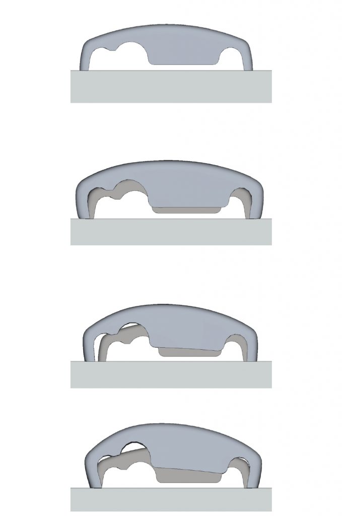
The functionality in highest demand from industry is the ability to perform distortion compensation (Fig. 2). The ability to output a pre-deformed shape that, when additively manufactured and sintered, will result in a nominal geometry, has the potential to change the way the industry designs parts for Binder Jetting.
Simufact Additive enables the user to define the final component geometry they are trying to achieve, and the required maximum surface deviation. From here, the software takes over and automatically performs multiple iterations of compensation, getting closer to the desired outcome with each step (Fig. 3). Out of this automated iterative compensation routine, the resulting geometry will have a non-uniform compensation vector across the geometry surface; applying more or less compensation at various regions on the part. While this capability was originally developed to support a PBF-LB compensation workflow, it is even more critical due to the highly non-linear deformations inherent to the BJT sintering process. It should be noted, though, that compensation is not a silver bullet, and not all deformations can be effectively compensated. It is required that the design first yield a stable, controlled deformation without excessive non-linear behaviour.
Simulation to enable BJT DfAM
The process of DfAM in BJT is not that different from other AM processes; only the ‘rules’ are different. Process simulation software can be an effective DfAM tool that enables one to evaluate the effects of the manufacturing process given the combination of inputs, including:
- Component geometry
- Sintering orientation
- Support/setter strategy
- Process parameters
- Material parameters
Changes to geometry may impact the desired orientation and support requirement. Changes to the orientation will likely also require changes to required supports (setters). All of these inputs will have an effect on the resultant part post sintering. It follows that the engineer must design the component geometry with the sintering orientation and support/setter strategy in mind; in an ideal case, the component would be dimensionally stable and totally self-supporting. However, this is generally not the case in practice. More often than not, a part that is not idealised for BJT is handed to the AM engineer responsible to build and sinter it effectively. In some cases, changes to the component design are available, in some cases, not.
Simulation software informs the designer of what will happen during manufacturing and enables them to quickly and efficiently evaluate in an effort to optimise the component design, orientation, and support/setter strategy. In this way, design engineers who do not have extensive experience and tribal knowledge of sintering behaviour may be able to evaluate various design trade-offs quickly and without the intervention of the more seasoned manufacturing engineers. When DfAM is done well, the engineer is able to find the optimal balance between part performance, dimensional stability, risk of build failure, post-processing effort, and cost. The iterative process of going from preliminary design to successful build and sinter can be reduced by several [design > print > sinter > inspection] loops.

The question is frequently posed (normally in the context of PBF-LB): Would you trade a bit of mass, stiffness, or whatever other performance metric is relevant for a part that will be guaranteed to build successfully, within dimensional tolerances, with no support removal required? The answer is: Maybe, but the compelling question illustrates what the design engineer may go through when generating new part designs. Process simulation gives engineers the opportunity to efficiently evaluate these design trade-offs with relatively low risk.
Another approach to determine the optimal design is through automated evaluation of many design variants. Simufact is able to be driven entirely by automated scripts. This capability enables the engineer to come up with potentially limitless design candidates for parametric/sensitivity investigation, queue them all up and run them overnight. Through the use of advanced automated result post-processing techniques, engineers can quickly review a large number of results and select the best design candidates for closer review.
Regarding accuracy and material characterisation
During development and validation work with industry partners, Simufact was able to achieve 95+% correlation (+/- 5% dimensional deviation) between simulation prediction and scan-based measurement. This level of accuracy of course requires special attention to material characterisation for a given ‘recipe’. Much like in PBF-LB, a recipe consists of many contributing factors including powder, binder, build parameters, debinding, and sintering process parameters. Recent observations indicate that the software delivers 80–90% accuracy of out of the box with default 316L material properties, improving to 85–95% with limited calibration effort.
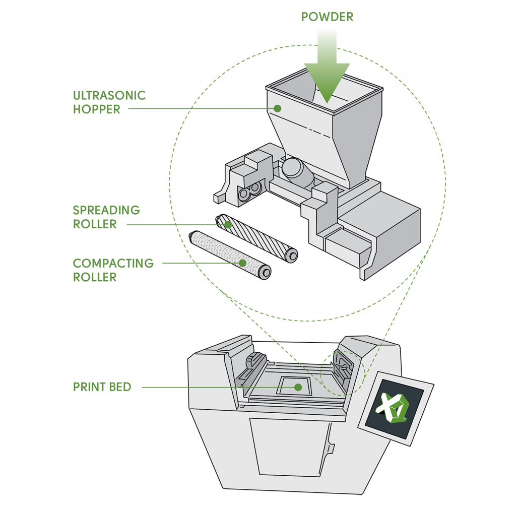
One important consideration is that the software requires input of an initial relative density which is assumed to be uniform across the part. While the solver is capable of considering a non-uniform green part density, that information must be known and provided as an input to the simulation. However, the difficulty in obtaining such a density distribution experimentally hinders the utilisation of this data in simulation. Based on simulation sensitivity studies performed, a pronounced effect of non-uniform green density distribution on sintering behaviour is observed. Logically, improved uniformity of green part density will result in more uniform sintered density and a more predictable deformation during sintering. Therefore, it is essential to qualify the build stage such that the desired green density is achieved. ExOne’s approach to reducing green part density variation lies with its patented Triple Advanced Compaction Technology (ACT), as shown in Fig. 4. Not all BJT AM machines can produce parts with the same level of consistency and uniformity in green part density.
Achieving success with ExOne
Over the course of 2021, ExOne has able to achieve success in working with Simufact Additive. ExOne has applied the software on multiple customer projects and validated its capability to support the BJT DfAM process. “Fundamentally, the software works,” stated Kyle Myers, Director R&D at ExOne. “We’ve proven it out with real parts with real challenges. ExOne’s goal was: does the software intuitively predict where parts would distort? And it does. As this area of digital sintering simulation is still very new, we’re really looking forward to how far a reliable simulation software can take the binder jet market in improving part design for sintering. Already, recent updates have improved the Simufact software to a place of enhanced understanding and acceleration of design, and we expect the whole field of sintering simulation to continue advancing rapidly.”
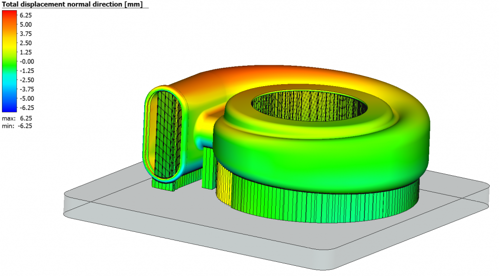
In the recent case of the Maxxwell Motors, the ExOne team wanted to evaluate feasibility for a radical new approach to build and support the copper windings during sintering. Simufact Additive enabled ExOne to determine that what seemed like a ‘crazy’ design would in fact work. Upon physically building and sintering the part, the results from physical and virtual tryout were more or less a match. In this case, ExOne was able to validate that the novel design was in fact feasible.
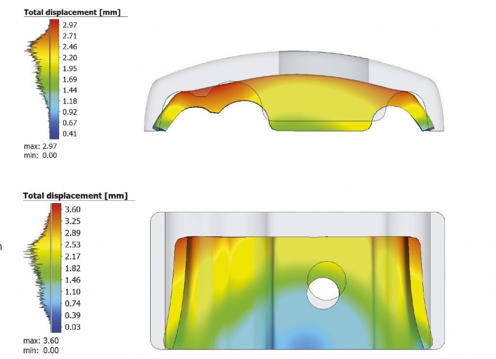
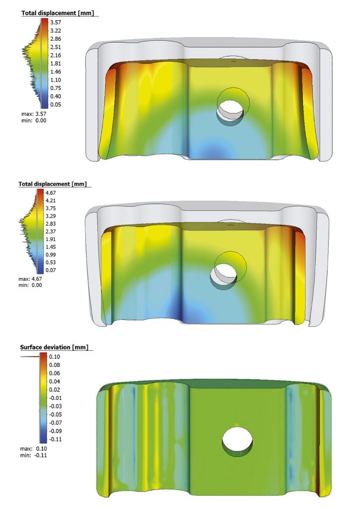
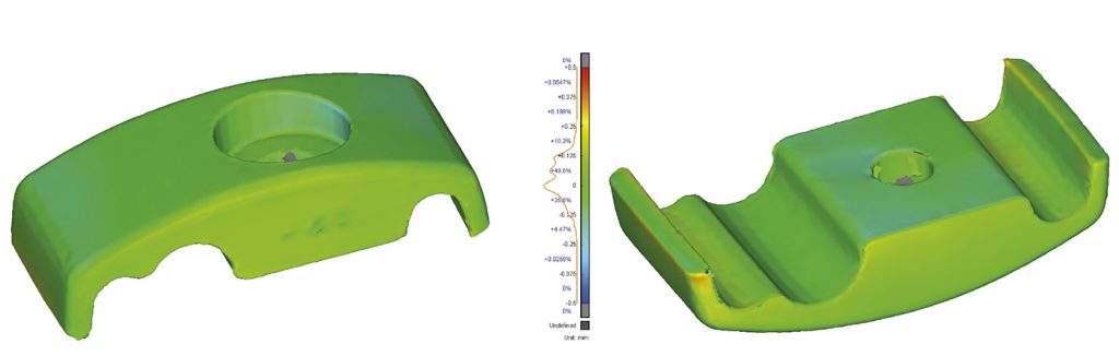
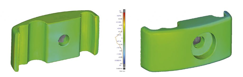
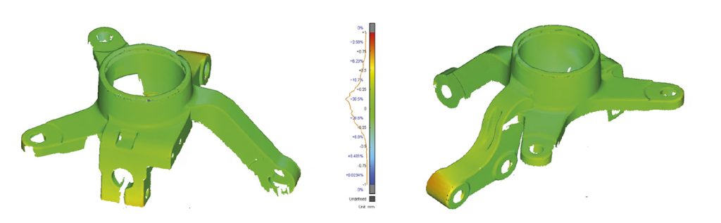
Two example applications are shared here to illustrate how the software has been applied at ExOne. The first example is a simple wire fastener that does not require a setter and was sintered in two orientations. Fig. 5 shows the simulation result when sintering the nominal geometry for both the horizontal and vertical orientations. The second example is a more complicated automotive-style steering knuckle that is built with a live setter, as shown in Fig. 6. In both cases, no special material characterisation was performed and all simulations were run with off-the-shelf 316L material properties that ship with Simufact Additive. All geometries were built in an ExOne Innovent machine with 316L powder and sintered in an Elnik 3045 furnace. The final sintered parts were then scanned using Hexagon’s Absolute Scanner and surfaces compared with a best-fit alignment.
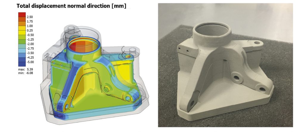
The two sintering orientations resulted in significantly different behaviours, as illustrated in Fig. 5. The horizontal orientation results in a bridge-type section where slumping due to gravity becomes the dominant driver of distortion. Friction also has a noticeable effect in this case, affecting how much the ‘legs’ will resist shrinkage laterally during sintering. The vertical orientation is more dominated by friction between the part and the baseplate. In this orientation, the resistance to shrinkage due to friction is very noticeable and results in a sintered geometry that is much narrower at the top than at the bottom. While the steering knuckle was a larger and much more complex geometry, it distorted more predictably due to the application of a live setter (support made from the same material as the part). A lack of unsupported or thin, free standing features meant that the shrinkage component was the dominant strain component affecting the sintering deformation.
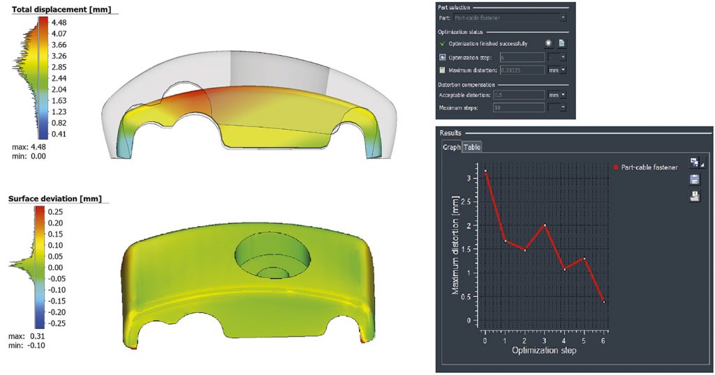
Only the cable fastener was selected for compensation. The horizontal orientation required six simulation-based compensation iterations to achieve the desired tolerance of less than 0.5 mm, whereas the vertical orientation required only two iterations. A selection of compensation iteration geometries compared to nominal are highlighted in Fig. 3. The progression of the compensation routine and results from the successful (sixth) iterations are shown in Fig. 7. Each simulation run took about 7 minutes to complete on a 4 core laptop.
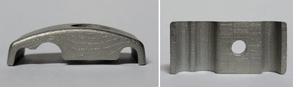
Fig. 8 shows the compensated, additively manufactured and sintered cable fastener for both orientations. It is visually apparent that the simulation software was able to effectively capture the relevant behaviours for both the horizontal and vertical orientations, and generate a compensated geometry that would distort into the desired shape. Figs. 9 and 10 provide a shape comparison between the scan data of the compensated, post-sintering physical specimens and the target nominal geometry used to drive the compensation. 99+% of scan data points are within +/- 0.25 mm of the desired nominal shape for both the horizontal orientation and vertical orientation.
Scan based evaluation of the steering knuckle simulation results also showed a positive outcome and good agreement between the simulation based predicted final geometry and scan data of the as-sintered nominal geometry is observed (Fig. 11). While not entirely within the desired tolerance of +/- 0.5 mm, approximately 91% of the measured surface was within that range. An additional consideration is that the steering knuckle is larger, measuring 72 mm at the widest point compared to 30 mm for the cable fastener. Holding the same absolute tolerance inevitably is more challenging on larger components. The correlation level could likely be improved through additional calibration of the friction coefficient.
The Simufact roadmap for sintering simulation
While these are still the early days of simulation software for metal BJT AM, Simufact has a detailed roadmap for where it plans to take the solution in the future. It plans to achieve this through a mix of in-house development, partnerships with industry, and funded research projects. Future capabilities may include:
- More material data shipped with the software, starting with 17-4PH and 4130
- A generalised material characterisation to reduce the effort of calibration
- Anisotropy of the part resulting from build orientation
- Considerations for different sintering environments
Conclusion
Metal BJT AM has the potential to open the application of AM to a much wider range of industries. When compared to other metal AM technologies, BJT can produce parts faster, cheaper, and without the effects of residual stress and strain due to melting and solidification. One of the main hurdles to its widespread adoption, however, is the need to manage complex sintering behaviour.
Reliable simulation software can be a powerful BJT DfAM tool, enabling the designer to rapidly iterate the design and manufacturing strategy to determine the optimal balance of dimensional control, robustness, cost, and speed. Through this study, Simufact Additive and ExOne have demonstrated that complex sintering behaviour can be effectively managed, lowering the hurdle towards industrialisation of metal BJT AM. Simulation software on its own does not make the BJT process work, but applying it effectively can increase industrialisation of the technology.
Contact
Jeff Robertson
Director of Business Development, Americas
Simufact and FTI, part of Hexagon
[email protected]
www.hexagon.com
Sarah Webster
Chief Marketing Officer
The ExOne Company
[email protected]
www.exone.com

LAST MONTH’S MOST-READ ARTICLES


