


Optimised thermal management in semiconductor fabrication using AI-enabled generative design and Additive Manufacturing
An unexpected consequence of the COVID-19 pandemic has been its impact on the multibillion-dollar semiconductor microchip market: at the very same moment as demand for consumer electronics skyrocketed due to global lockdowns, the supply of semiconductors was bottlenecked by production disruptions. Now, supply chain shortages threaten the production volume of the industries dependent on these parts. Scott Green and Niels Holmstock, 3D Systems, and Lieven Vervecken and Gert-Jan Paulus, Diabatix, explore how metal AM can be used to increase efficiency in semiconductor fabrication and boost the speed at which these vital components can be produced. [First published in Metal AM Vol. 7 No. 2, Summer 2021 | 25 minute read | View on Issuu | Download PDF]
Metal Additive Manufacturing is easily connected with market segments such as aerospace, automotive, and healthcare, but the value AM provides is unique, and can be applied to any market segments wherein the performance and function of a system can benefit from function-first component design methodologies.
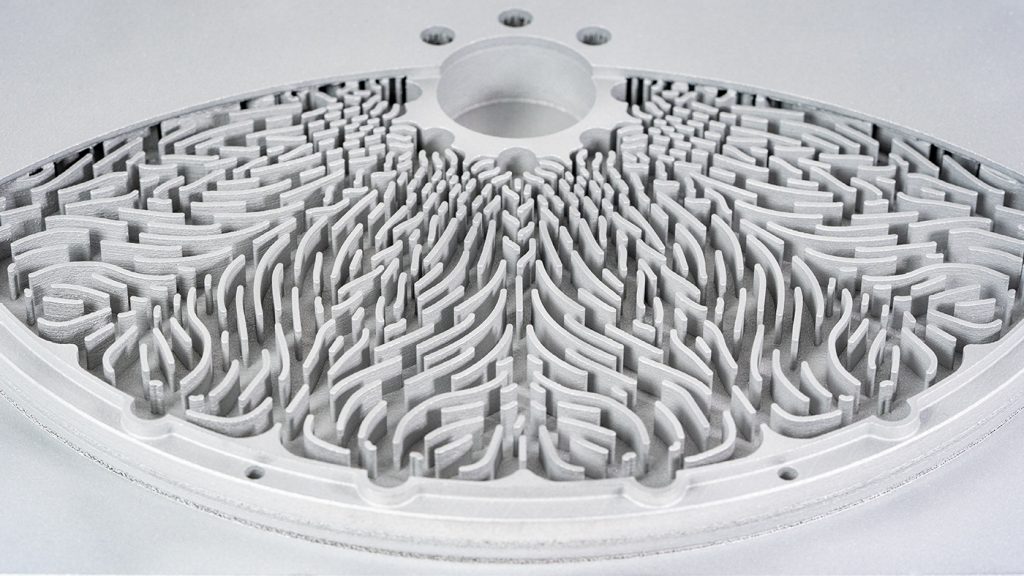
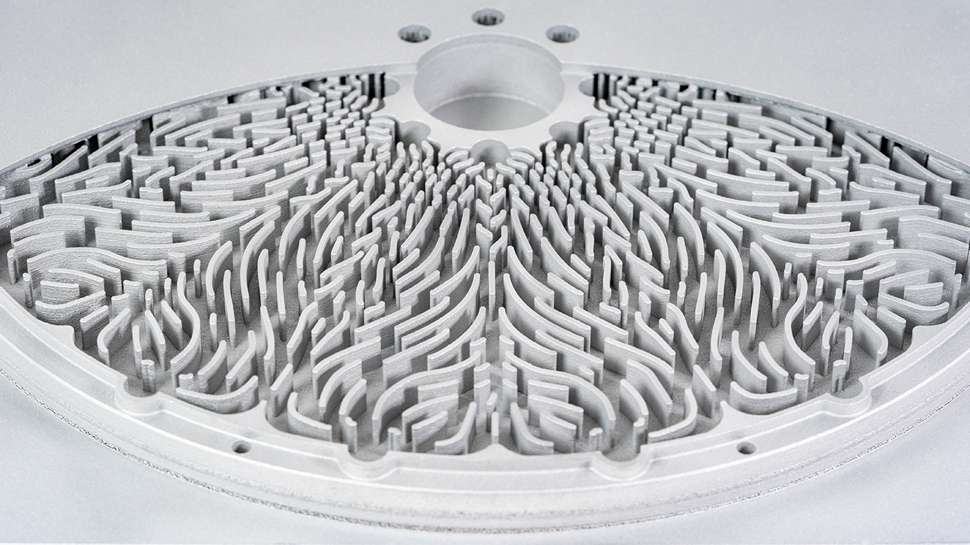
In 2021, it has never been more critical for semiconductor fabrication equipment to have the highest possible productivity, reliability, and technical capability to help alleviate the burden of global chip shortages. Sometimes, nothing major changes, and new endeavours are not attempted, until there is a deadline, pressure, or an emergency – and the race is on. Now, novel AI-enabled generative design software, plus production-quality metal AM, are working together to solve major performance and supply chain challenges in the semiconductor capital equipment industry. Fig. 1 shows a metal AM wafer table with a sophisticated cooling structure, key to increasing the efficiency of semiconductor manufacture.

Microchip fabrication and supply chain shortages
Microchip fabrication is considered state-of-the-art in advanced manufacturing. This industry is driven by the pursuit of faster, more efficient processors and higher capacity memory chips where we see racing vectors driving ultra-high levels of detail fidelity, resolution, and precision, all wrapped within massive investments in advanced tooling systems and infrastructure. Multibillion dollar production lines depreciated over billion-unit production runs present staggering metrics, as well as massive continuous optimisation initiatives. When it comes to optimising the hardware and tools that exist within these production lines, the emergence of industrial Additive Manufacturing solutions has started to present a significant opportunity to engineers and designers at the very front line of problem solving.
Now, more than a year into the pandemic, we’re all too familiar with its impacts, not least of which is the blow dealt to supply chains. An unexpected side effect of the pandemic has been a global shortage of semiconductors, which is disrupting the production of all sorts of consumer products, from cars to electronics. In December 2020, Volkswagen said that bottlenecks in the supply of semiconductors meant it would produce 100,000 fewer cars in the first quarter of 2021, as its parts makers were unable to secure supplies. Nissan, Renault, Daimler, and General Motors are also struggling with the shortage, which may lead to production being reduced by as much as 20% per week.

On top of this, due to the pandemic requiring the vast majority of the population to work remotely and stay at home, demand for consumer electronics, such as laptops and entertainment devices, has skyrocketed. The manufacturers of these devices are competing for microchip supply with the automotive industry, as modern vehicles come with increasingly sophisticated technology and computing built into their designs.
If we need more chips, can’t chip manufacturers just increase manufacturing capacity? In theory, it sounds easy enough, but production capacity and technology are proving to be hurdles in achieving these goals. For semiconductor fabrication plants to increase production, they need to install new manufacturing lines. These lines require new equipment, and capital equipment manufacturers are innovating to help fabricators meet the increased demand. However, these tools are complex and expensive, with a long product development cycle; in some cases, lead times are six to nine months. As such, it is difficult for capital equipment manufacturers to pivot production lines that rely on traditional manufacturing technologies in order to scale proportionately to unexpected demand growth like we’re seeing today.
Additive Manufacturing to the rescue
Within silicon wafer tooling there are many complex phenomena with which to interact. Temperature, inertia, turbulence, resonance, vibrations, precision, wear-and-tear, and ultra-high level sanitation standards driven by a zero-tolerance policy for contamination, converge to present a significant challenge, while, at the same time, offering many opportunities for optimisation. This is where Additive Manufacturing comes in. AM allows for step changes in component performance and efficiency.

Following the traditional rules of design and manufacture as they apply to conventional parts, performance is always somewhat compromised, since the dawn of computer-aided design, or even before. By using Additive Manufacturing, and specifically by embracing design for Additive Manufacturing (DfAM) and the philosophy of ‘design for function’, companies at the frontline of problem-solving are able to innovate in ways previously considered impossible. AM’s rapid adoption in semiconductor capital equipment (semicap) manufacturers is improving quality, production, technical capability, and reducing supply chain risks.
There are countless interesting challenges in semicap, but they can be boiled down to three key topics of function-first design:
- Fluid manifold flow optimisation
- Part count reduction and mass management
- Thermal management
Fluid manifold flow optimisation
Traditionally, these very complex components are time consuming and difficult to fabricate, requiring multiple manufacturing processes, from sheet metal folding to hydroforming and tube bending, all integrated with assembly steps. The net result never quite approaches the perfect solution, as the vast assembly processes and steps are full of potential points of failure. When AM is applied, designers can present the perfect tubular system, using advanced fluid flow computational fluid dynamics (CFD) to influence and, in some instances, automate the creation of forms, as well allowing the integration of sophisticated baffle strategies which allow for minimising turbulence while maximising flow efficiency. The benefit of such architectures is the minimisation of vibrations and resonance that correlates with net turbulence within systems, as shown in Fig. 2.

Turbulence and vibrations impact the precision of output, and, in a world where nanometres count, this presents significant capability. Using 3D systems’ DMP 350 platform engineers were able to realise a 90% reduction in liquid-induced disturbance forces to reduce system vibration and realise 1–2 nm accuracy improvement.

Part count reduction and mass management
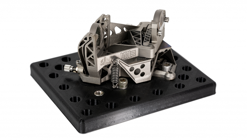
An added benefit of AM is its ability to grant designers access to significant levels of component consolidation, which ultimately drives the design efficiency principle of part count reduction, thus leading to the expression of complex manifolds as monolithic components with no assembly required. This simplifies not only supply chain lead time, but also makes the process of design easier. In some examples, we have seen lead times of months become hours, driven by the elimination of tooling, assembly, and the associated inspection process. A part count reduction of up to 50 x has been achieved through component consolidation in some of these complex systems. An example of a highly complex optical assembly produced in one part using metal AM is shown in Fig. 3.
Down selection of alloys to cheaper lower density materials is just one driver of weight reduction. DfAM generally presents significant opportunities for more efficient design through bulk material savings. Lighter weight assemblies in semicap have multiple benefits, including:
- Lower thermal mass, which results in faster thermal condition response
- Lower inertia results in opportunities for faster and higher precision conveyance, and more precise stop and start acceleration/deceleration profiles, while reducing wear and tear of mechanisms
- Reduced mass/inertia combined with DfAM-based improvements in the stiffness of subcomponents in high-velocity reciprocating mechanisms, which also reduces vibration generation within systems
At a silicon wafer tooling company, engineers were able to realise a 50% weight reduction for reduced inertia, with a boost in stiffness of 23%, resulting in a higher resonant frequency and reduced system vibration, all equalling improved speed and productivity.
Thermal management
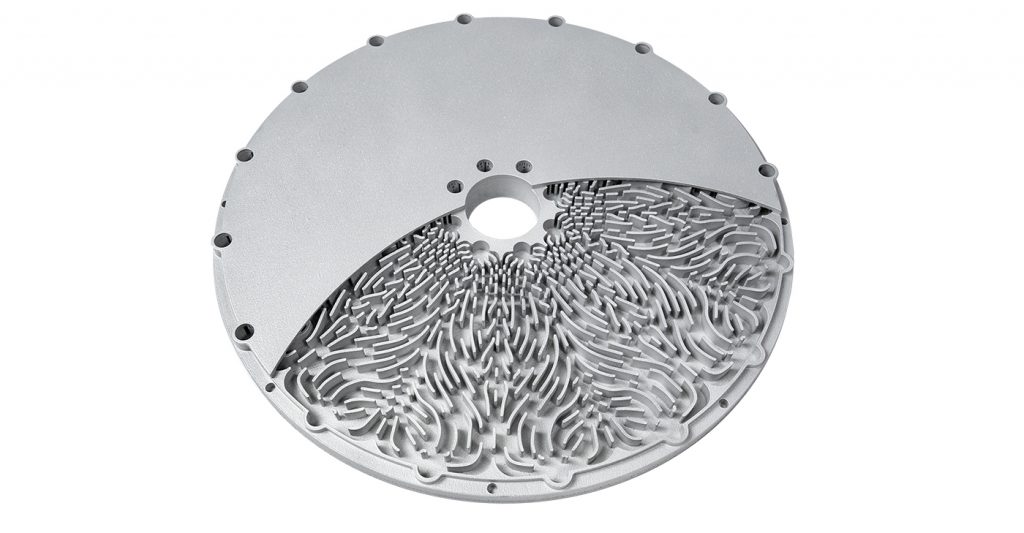
Another application where we see AM presenting step changes in capability is in the production of highly efficient wafer tables (as shown in Fig. 4). These tables are used for handling and fixturing the silicon plates during the manufacturing process. Thermal variation causes minute changes in the expansion of materials. Over time, these thermal gradients and fluctuations can create scenarios where the position of structural elements being additively manufactured and accumulated on the surfaces of the silicon wafers can shift (commonly known as edge placement error, or EPE). To solve this, engineers are turning to AM to design, develop and manufacture next-generation silicon wafer table architectures.
One silicon wafer tooling company was able to realise a sixfold improvement in thermal performance and a fivefold stabilisation improvement. The thermal profile within the conditioning ring was able to see a ΔT improvement from 13.8 mK to 2.3 mK, with a thermal temperature gradient reduced from 22 mK to 3.7 mK, in a more responsive system presenting a time constant moving from 7 s to 1.5 s.
The efficiency, performance, and responsiveness of the AM architecture were so high that the engineers were able to look at actually regressing an alloy selection from expensive copper to cheaper and lighter aluminium – an unanticipated benefit of a DfAM design optimisation functionality offset. In the case study below, we will discuss a cutting edge approach to achieving optimal thermal performance.
We have previously discussed what technical values AM provides at a component or subsystem level, but it is also important to understand the pressures on semicap, which make applications such as the following wafer table function optimisation case study a perfect example of a confluence of values and benefits.
Yield
With semiconductor equipment typically being large and costly, customers are expecting significant yield from a single machine.
Reliability
The reliability of the semiconductor equipment is key with outages leading to significant losses in missed production time.
Precision
Moore’s Law expects transistors to reduce in size every two years. To meet this expectation, transistor density is increasing, and phenomena such as EPE in semicap are becoming harder to overcome.
Wafer table case study
Although we see an increasing demand for AM components across the entire process chain of microchip production, lithography has been at the forefront of metal AM adoption. Lithography is a key step in the microchip production process and a significant contributor to transistor density on a die. As this is an early step in the production chain, having a high yield is vital. The wafer table is one of many key components in semicap, especially in lithography.
There is an ongoing transition away from human-made design towards computer-generated (i.e. generative design), and human-aided design (as opposed to computer-aided design).
Generative design and structural topology optimisation are relatively well understood as an approach in 2021, but there are many unique segments of topology optimisation. Uniquely, in this case, we will discuss topology optimisation as a product of automated, massive parallel iterative loops of computational fluid dynamics simulation and DfAM. Here, we detail the realisation of a semiconductor wafer cooling table demonstrator from design concept to Additive Manufacturing. As part of this exercise, we will compare traditional cooling design to generative cooling design and how it affects performance and design effort.
Traditional design workflow
As in many engineering disciplines, the traditional design workflow for cooling channel design is dominated by trial and error. A designer draws a cooling design, which can be tested against the specifications through either CFD simulation or prototype and practical testing. Benchtop tests can be simple and easy, and, depending on the application, full system integrated tests can be challenging, with schedule and cost being major factors.
When designing a cooling pattern, the first guess is typically based on rules of thumb and directly reused or rescaled designs of earlier work; with enough experience, you can apply heuristic design rules to get a good starting point. Rarely does this work out on the first try; after a failure, the designer must make continued iterations. This approach is only slightly better than blindly designing.
Traditional parametric CAD has the framework for generating many design options and can be partly automated. It takes a moderately experienced designer to invoke a design table of sorts, and define a set of parameters, such as channel width, number of turns, etc., with this structure allowing for rapid iteration on a complex design by parameter changes. However, it is important to understand that, with this design approach, the performance of the final design is directly correlated to the quality of the initial guess. As there is no guarantee that this initial guess is even sufficiently close to the desired result, there is no guarantee the desired result can be reached with even huge parameter changes.
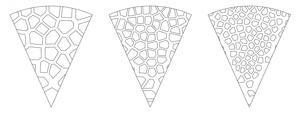
To illustrate, if a designer starts with a design characterised by parallel cooling fins, they will never be able to generate anything other than derivations of that design strategy within some narrow variations (Fig. 5). This approach typically leads to multiple lengthy and costly iterations and introduces significant uncertainty on the design cycle time. There can also be major implications on the programme schedule if lengthy manufacturing processes are used for production; weeks and months can pass between iterations, knowledge and experience, allowing momentum to be lost. Furthermore, if the designer did not take manufacturing limitations into account and the analysis was done by simulation, there is a significant risk that the design will not even be manufacturable, despite all efforts. These issues, however, can be addressed with generative design and Additive Manufacturing.
Generative design – optimising for Additive Manufacturing
The American Psychological Association and National Institutes of Health indicate that humans are only able to manage simultaneous consideration of roughly three to four concepts. This natural human limitation has been a driving force in mechanical design for as long as parts have been made. When designing high-tech components where function is critical, the overwhelming consideration of physical and functional constraints alongside manufacturability parameters become too much for one person, and whole teams of people and specialists must get involved, thereby increasing the overhead and lead time.
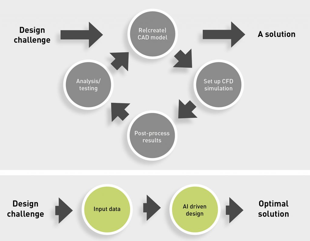
Generative design is an automated design process that requires minimal human input or interaction to achieve highly-optimised design files with ideal functional performance. By making use of physical modelling, massive computational resources, and state-of-the-art optimisation and artificial intelligence techniques, generative design can overcome the limitations of a traditional CAD design approach. The overwhelming and simultaneous consideration of parallel constraints is reduced to a few simple steps for setting constraints in a software program, and a generative design engine does the rest. The starting point for generative design is not a best guess, but simply a description of the design target, an indication of the available design space, and a set of design limitations such as manufacturing constraints. When using generative design software, engineers are no longer designers in a committee, but become managers of their own virtual design team. A comparison of the conventional and generative design cycles, and the degree of human involvement in each, is shown in Figs. 6 and 7.

Setting up the generative constraints
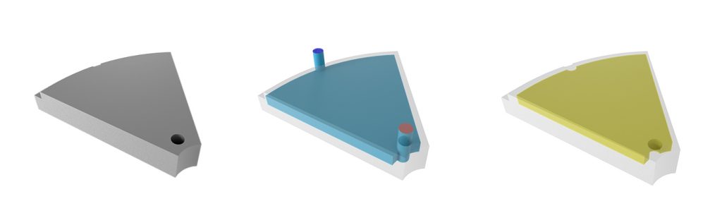
In the first step, the creation of the design setup, all information required to create the design is collected. The starting point is a set of CAD bodies that include the geometries of the main components, the domain in which the coolant can flow, and the domain that represents the design region (Fig. 8). Once the geometric information is available, the boundary conditions can be applied. Similar to a traditional CFD simulation, information such as material properties, coolant properties and pass/fail heat map tolerances are required.
Finally, the targets of the design need to be set. These targets contain information about the design objective, the system constraints, and the manufacturing limitations. Almost any design target can be chosen as long as a mathematical equivalent can be formulated – for example, cost or manufacturing time reductions can be achieved alongside more traditional requirements regarding temperature, weight and pressure.
The actual generative stage is an iterative process that does not require human interaction. The process collects data from thousands of sequentially executed advanced CFD simulations to make measured design changes in each step of the process. Besides the physical input from the CFD simulations, feedback on manufacturability is collected during each step of the process. Because of this computationally-heavy workload, the process is executed through commercial cloud services, using several hundreds of CPUs in parallel. During the process, the cooling structure is gradually built within the designated design space, considering the physical properties of the material and the coolant.
After completion of the design process, the generated design is converted into a common CAD file format and ready for use. Because simulation is an integral part of the generative design process, a performance analysis is immediately available, as well, which allows for the assessment of design quality and to unveil new opportunities, such as reducing the component envelope.
The main objective in this case study is to maximise the thermal uniformity of the wafer table, while not inducing fluid pressure drop in the system. A bonus benefit of an advanced cooling strategy would be a minimal time to stabilised operating temperature, resulting in an incremental production rate increase.
Physical constraints
Geometry
Disc-shaped thermal load with an internal diameter of 60 mm, an outer diameter of 300 mm and a thickness of 28 mm
Material choice
- Aluminium (AL6061-RAM2), due to its good thermal conductivity and moderate strength for this application
- Typically, a thermal table does not require a very high-strength material due to its limited physical load
- Ductile materials such as copper would not be appropriate. Though copper alloys provide significant thermal conductivity values, they are much too soft for loads and high accelerations
- Low cost, prolific, easy-to-additively-manufacture aluminium alloys containing silicon may appear to be the right fit for such applications based on datasheet values, but, from an application perspective, the silicon content is unacceptable for many applications, either due to dangerous fluid reactivity or concerns around silicon contamination of the wafer product
Operational constraints
- Distilled water is used as a coolant so there are minimal concerns for alkaline corrosion
- The heat source presents itself uniformly at roughly 10 Watt over the full surface
- At the inlet, the volumetric flow rate is fixed to 7.5 litres per minute at a temperature of 21°C
Result constraints
- The target is maximising the temperature uniformity over the surface while considering that it needs to be at least below 0.1°C
- The pressure loss between the inlet and outlet is set not to exceed 70 kPa
- To ensure that the design can be manufactured, the manufacturing guidelines of PBF-LB Additive Manufacturing on a DMP machine are selected: namely, a maximum overhang angle of 45° and a minimal wall thickness of 150 µm. We assume a flat build orientation, which is typically preferred in AM for large discs. This flat orientation has the added benefit of creating a flat control surface on the bottom during wire EDM plate removal
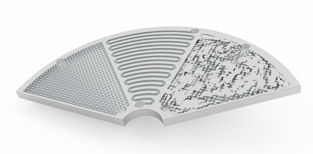
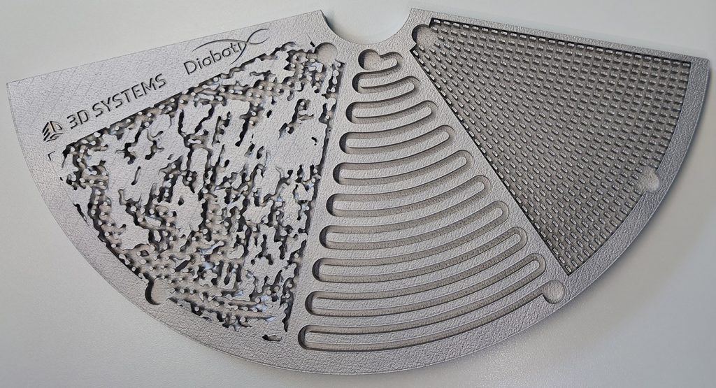
By making use of the periodicity in the design, we divide the disc into sections of 45° with different cooling channels and compare performance (Fig. 9). We assume one inlet and outlet per section. In this article, we limit our analysis to two conventional designs and one generative design. The state-of-the-art Diabatix ColdStream® platform is used for this case study. This platform is the first to offer generative design for flow and thermal components. All analyses and generative design are performed by Diabatix®.
Conventional design 1
Cooling fin array
One common design strategy for cooling is ‘pin-fin’, shown in Fig. 10. The pin-fin strategy is easy to design manually and creates a large heat exchange interface. Yet, from an AM point of view, this design has two disadvantages. First, gaps between fins cannot be more than 4–5 mm in metal AM, as they need to provide enough support for the closing surface over the cooling channel. Second, by not making use of the third dimension, there is room for improvement.
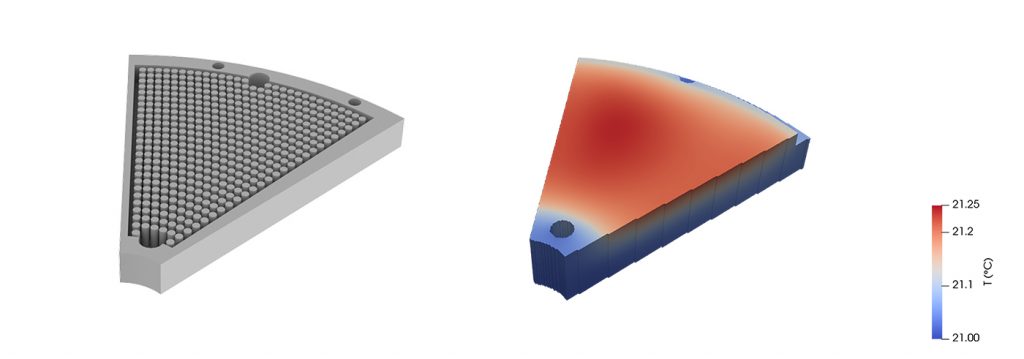
When analysing the performance of the fin array, we noted that the pressure drop of 22 kPa is below specification. The temperature peaks at 21.24°C and the temperature spread is not within the 0.1°C constraint. The coolant primarily follows the path of the lowest resistance, which is the direct connection between the inlet and outlet. As a result, local hotspots are difficult to avoid. Variations on this design can be imagined, which attempt to force fluid divergence at the inlet and convergence at the outlet. Changing the pin density can help reduce the occurrence of hotspots, but will strongly increase the pressure drop, as well. Summary of results:
- Max temperature (21.4°C)
- Temperature gradient (0.12°C) FAIL
- Pressure drop (22 kPa) PASS
- Time to stable temp (410 sec)
Conventional design 2
Linear serpentine channel
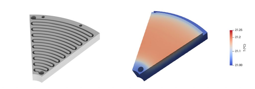
Another, even more common design strategy often employed is the serpentine channel, shown in Fig. 11. Using this type of channel in AM components imposes a constraint on the channel’s width. As with the previous pin-fin design, there are maximum bridging distance constraints. As a result, a fairly long channel is required to provide sufficient coverage of the surface. Furthermore, prior experience tells us sharp switch-back style interior channels can create challenges in maintaining ideal pressure in operation. Even more challenging are the powder removal implications for such a strategy.
When analysing the simulated performance of this traditional channel design, we remark that the maximum temperature is only 21.18°C and that the temperature spread of 0.09°C passes the bar, but, as expected, the pressure drop of 420 kPa is far beyond acceptable. This is a direct consequence of the length of the channel.
More complex derivations of the strategy which can help reduce the pressure drop and maintain a high-temperature spread are possible. One such example would be multiple parallel serpentine channels with individually shorter overall lengths and comparable, or longer, cumulative channel areas. This could be preferable, but would require a longer initial design time, and likely a long tail of iteration on proper Inlet channel divergence and outlet channel convergence strategies. Summary of results:
- Temperature gradient: (0.09°C) PASS
- Pressure drop: (420 kPa) FAIL
- Time to stable temp (409 sec)
Generative design
The best of all worlds
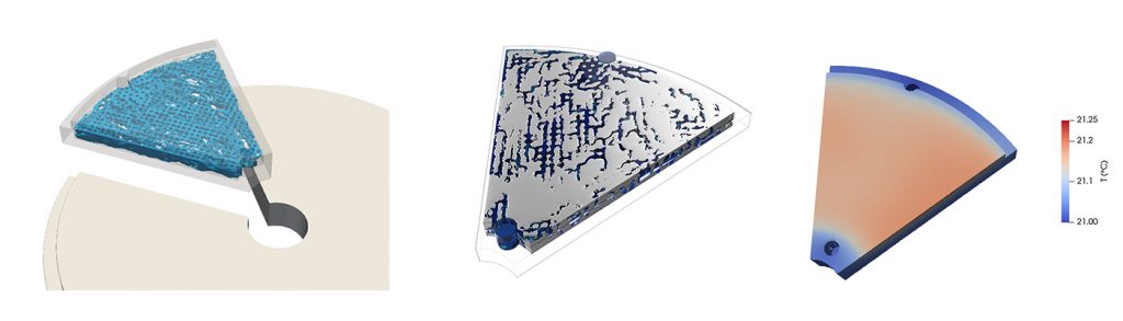
As previously described, the generative design (Fig. 12) delivers on the promise of highly optimised geometry with minimal input constraints, creating optimised and unique solutions to specific problems. It is possible, with enough generative design experience in a narrow range of problems with sufficiently wide parameters, that a designer could develop a heuristic approach to solve structural design problems on their own. But, in the use cases of thermal management with fluid flow and precision constraints, a new range of extremely complex solutions are being produced, which become nearly impossible to generalise with a human-created design strategy, while maintaining the significant technical merits the computer-generated solution provides.
By making active use of the third dimension, a complex network of channels is created that directs the flow to the regions of interest. By design, the structures are self-supporting and obey the required minimal and maximal feature sizes. These shapes are well beyond human engineering capabilities. In this practical example, we will explore the efficiency and details of this novel approach.
The performance of the Diabatix ColdStream results fall perfectly within acceptable end tolerance ranges for both pressure drop and temperature uniformity. The peak temperature is 21.18°C, an improvement of 25% compared to the fin array, and the lowest of the three designs. Also, the temperature spread is with 0.1°C on target. The temperature is very similar to the serpentine channel, but the 40 kPa pressure drop of this design is more than 10 times lower. This performance is achieved by alternately making use of smaller channels with high heat transfer rates and high-pressure drops, as well as larger channels with both lower heat transfer rates and low-pressure drops.
By using the Diabatix ColdStream platform, preparation of the design process and analysis of the results only requires a few hours of human engineering time. In return, a design is generated that easily outperforms conventional designs. Furthermore, manufacturability can be ensured.
The drawback of this is that the process is computationally expensive. At the time of writing this article, this problem can take several weeks to calculate completely even while using hundreds of CPUs in parallel. Yet, it does not require any human intervention, nor any additional design iterations afterward.
This makes it a very effective method for design cycle time reduction. Like the design process, the manufacturing process also runs without any human presence, allowing it to function overnight, during weekends and over holidays. Summary of results:
- Max temperature: 21.18°C
- Temperature gradient: (0.1°C) PASS
- Pressure drop: (40 kPa) PASS
- Time to stable temp (381 sec)
Comparative summary
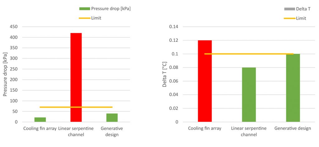
In this study, three cooling strategies were investigated: a cooling fin array, a linear serpentine channel, and a Diabatix generative design. The generative design approach produced an optimised 3D geometric solution, which satisfied the overall temperature gradient constraint, exceeded the pressure drop constraint and satisfies metal AM constraints. An unexpected benefit of the generatively-designed component was a 29 sec reduction in the time required for the component to get to stable temperature (Fig. 13). This ~7% reduction in wait time translates directly to increased productivity, thus more wafer product produced per day.
Metal AM workflow

In a typical AM workflow after the design phase, we enter the build file generation phase. Using 3D Systems’ 3DXpert® comprehensive Additive Manufacturing software (Fig. 14), the following steps were performed.
- Positioning and orientation of the 3D file for manufacture
- Rescaling the 3D file to account for shrinkage that occurs during manufacture
- Add material for post-processing where needed
- Add manufacturing supports
- Build simulation
- Final slice & hatching
- Export package for manufacture
No matter which AM tool is targeted, the general workflow is the same. However, there are some unique aspects of the implemented solution that require some illustration.
In 3DXpert, the combination of slicing and hatching is automated based on a selected technology profile. For standard users, a handful of default profiles are provided for each material, which will result in good mechanical properties. Expert users have the option to tweak and create their technology profile, leading to a high degree of optimisation, but this can also increase the risk of not getting validated results.
There is also valuable flexibility in user-defined build style zones. These zones can be defined around critical features (in full 3D) and can be assigned build style profiles. This novel build style assignment strategy allows the user to apply constraints to individual features on a part resulting in the best mix of speed, quality, and accuracy for any given project’s unique requirements.
Additionally, full build simulation technology is quite accurate, and increasingly powerful computational simulation tools are available to simulate the result of the print process without having to print the part. This can greatly increase the chance of first-time-right manufacturing and reduce scrap costs. By making use of 3DXpert’s integrated Additive Works Amphyon technology, significant reductions in cost and time spent during trial and error can be realised, allowing for faster time to successful manufacture.
Post-processing
In metal AM, the Laser Beam Powder Bed Fusion (PBF-LB) process is typically only the beginning of the production process, with parts undergoing multiple post-processing steps. Often seen treatments are:
Heat treatment
Relax any residual thermal stresses and/or optimise the material’s microstructure for the relevant application
Base plate removal
Typical wire-EDM for accurate cuts or bandsaw for rough cuts
Support removal and shot peening
Often still a manual process, but automated processes are arising
Finishing
Chemical finishing and smoothing are common practices for high-requirement parts
Machining
CNC machining of high-precision interfaces is typically applied, but it is advantageous to apply proper DfAM consideration to reduce machining and associated tool costs
Cleaning
Finished part cleaning for application with high cleanliness requirements
Metal AM value driver
When quoting components for metal AM production, we notice that many companies still make their buying decisions solely on the purchasing cost of each component. Although the price for metal AM is steadily dropping, the price for metal printed components is still, to date, more expensive.
The true value of metal AM, however, lies in the total cost of ownership (TCO) of the solution; this includes many factors, and is especially true for semicap. By achieving higher performance through optimised components, we have seen many cases where, thanks to higher performing systems, the amount of required systems to meet a certain production goal is reduced, thereby significantly reducing the total cost of the solution.
Another example of improved TCO is the lifetime of the component. By integrating and optimising component designs, the lifetime of an additively manufactured component is often significantly increased over its traditionally made counterpart. We have seen examples where a metal AM optimised part had a 20% higher purchase price but the lifetime is trebled compared to its non-AM counterpart. This leads to a significant cost reduction over the lifetime of the solution but is often not taken into account when making the purchase decision.
Conclusion
In this article, we demonstrated the practical development of improved cooling strategies for wafer tooling. The novel generative design approach (using Diabatix’s ColdStream platform) automatically generated optimal self-supporting cooling structures which reduced overall temperature gradients, maintained fluid pressure within system requirements, and presented an incremental reduction in time for an entire system to produce wafer product. Manufactured as a monolithic single part by 3D Systems’ Application Innovation Group with 3D Systems’ direct metal additive technology, the resulting part also presents a reduction in manufacturing time and increase in components reliability over traditional manufacturing methods.
As semiconductor capital equipment manufacturers race to meet the demand for new fab equipment, new opportunities for improved quality and performance, and supply chain optimisation arise through function-first design methodologies through related software tools. These are then able to be realised through direct metal Additive Manufacturing and the available materials on the market. Extensive practical experience can be applied through full solution providers, significantly reducing wasteful trial and error and speeding time to market during this critical time for the industry.
Authors
Scott Green
Principal Solutions Leader,
3D Systems
[email protected]
Niels Holmstock
Team Lead, Industrial Application Development, 3D Systems
[email protected]
Lieven Vervecken
CEO, Diabatix
[email protected]
Gert-Jan Paulus
AI Design Engineer, Diabatix
[email protected]
LAST MONTH’S MOST-READ ARTICLES


