Making the unmakeable: How metal AM is bringing the aerospike rocket engine to life
The history book of engineering is filled with concepts that failed to achieve success because they were ahead of their time. This was almost the case for the aerospike rocket engine, recognised in the 1950s as a strong concept and tested by NASA in the 1980s and 1990s, but found to demand too much of the manufacturing and materials technology available at the time. Metal AM magazine spoke with Pangea Aerospace and Aenium Engineering about reinventing the aerospike for the 21st century, and how Additive Manufacturing allowed them to 'make the unmakeable' – pushing their expertise in AM, materials science and Design for AM to its limits in the process. [First published in Metal AM Vol. 8 No. 1, Spring 2022 | 30 minute read | View on Issuu | Download PDF]
Aerospike rocket engines were first conceived in the 1950s as a high-performance alternative to more traditional bell nozzle configurations. However, the shutdown of major space programmes, together with the manufacturing effort associated with their complexity, led to a period of relatively low research and industrialisation effort. Recently, aerospike rocket engines have experienced a resurgence of interest because of their altitude adaptation properties and advantageous performance characteristics compared to bell nozzles. Furthermore, the ongoing maturity level of Additive Manufacturing processes and materials for propulsion applications makes it possible to build an economically viable aerospike engine with reduced lead time.
Two European companies based in Spain, Pangea Aerospace, and Aenium Engineering, are working together to advance the aerospike rocket engine concept for the 21st century through a focus on nozzle design, advanced AM processing and post-processing, as well as exploring material science and metallurgical approaches on new high-performance copper alloys to resist the harsh heat flux/mechanical strength requirements of this application. The alliance between both these companies has resulted in a breakthrough in aerospike rocket engines and the firing of the first liquid oxygen/liquid methane (LOX/LNG) dual regeneratively cooled aerospike to be additively manufactured in history. DemoP1 packs 20 kN (~2 tons) of thrust in just above the dimensions of a football. It does that thanks to a combustion chamber pressure in excess of 50 bar and a near-stoichiometric mixture ratio, yielding a hot and energetic flame causing heat fluxes in the walls up to 50 MW/m2. These numbers make DemoP1 an ambitious demonstrator to design and operate, especially at this small scale where cooling requirements are the most stringent. The parameters of DemoP1 do not fall short of those found in some modern operational engines. To give an idea, if DemoP1 would be attached to a small launcher weighing around 1.5 tons, it could easily reach the threshold of space, topping at 120 km.

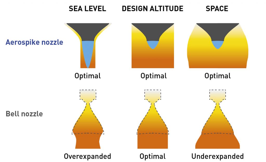
Explaining the benefits of the aerospike rocket engine concept, Federico Rossi, Head of Propulsion & co-founder of Pangea Aerospace, stated, “The aerospike concept is considered the ‘holy grail’ of rocket propulsion because of aerodynamic altitude adaptation. Typically, modern rockets employ a bell-shaped nozzle to convert thermal energy into pressure and kinetic energy and propel the spacecraft against gravitational forces. Aerospike engines carry out this process more efficiently.” The plume exiting a bell nozzle, composed of hot combustion products, behaves differently depending on the altitude at which the rocket is flying. “When the rocket is lifting off from sea level, ambient pressure is high and the plume is forced to compress as soon as it exits the solid walls of the bell. In this condition, the bell nozzle is referred to as ‘overexpanded’ because its exit pressure is lower than the ambient pressure in the lower parts of the atmosphere.” This condition is intuitively associated with a suboptimal performance level and the overexpansion can be so severe as to cause airflow to enter the nozzle, causing asymmetric flow separation and sudden nozzle structural failure.
As the rocket climbs, bell nozzle performance increases until reaching design altitude, where the exit pressure is equal to the pressure of the surrounding ambient. This condition is referred to as ‘optimal expansion’, and is associated with the one trajectory point where this nozzle operates at peak efficiency. When it has climbed past this point, the nozzle enters the ‘underexpanded condition’, where its performance keeps increasing simply because of the reduction in the surrounding ambient pressure (Fig. 2).
“An aerospike nozzle encounters the same operating conditions throughout its trajectory, but its geometry gives the plume the intrinsic tendency to ‘self-tune’ to an optimal expansion condition. Especially at sea level, the flow from an aerospike immediately ’feels’ the higher ambient pressure and, as a consequence, is squeezed against the walls of the nozzle, thus compressing and increasing its pressure to match that of the ambient.” This increase in pressure, applied on the nozzle walls, results in a higher thrust force pushing the nozzle along its direction of motion.
The aerospike, when compared to a bell, benefits from this increase in thrust from sea level to roughly the altitude of optimal expansion. In terms of trajectory, this typically means the first 10 km of the rocket ascent, when the vehicle is heaviest (thus the highest thrust is required to accelerate it against gravity). This finally yields to a more efficient nozzle when it is needed, and makes the aerospike 10–15% more efficient than its bell counterpart for vehicles in the micro-launcher class. For larger scales, the aerospike can be made even larger, up to the point where its performance gain approaches 20%. With the remaining rocket parameters being constant, this equates to a payload increase of the same magnitude or even higher.
Rocket engine propulsion and the role of cooling channels
“One of the most important design parameters affecting the performance of an aerospike and, in general, of rocket nozzles, is the expansion ratio: a measure of how much the nozzle allows the flow to expand,” Rossi continues. “The higher the expansion ratio, the larger and longer the nozzle becomes. A high expansion ratio is usually desirable for bell nozzles, because the engine, although it works less efficiently at sea level, will maximise its performance at higher altitudes. For an aerospike, this is even more important, because efficiency at sea level is retained, even with a high expansion ratio, as the flow will still behave optimally. Therefore, for an aerospike nozzle, it makes sense to have the highest possible expansion ratio.”

What, then, prevents a designer from building an aerospike rocket engine with a very high expansion ratio? “Dimension is one key factor,” stated Rossi, “but the most notable factor is cooling requirements. In fact, a high expansion ratio leads to a bigger nozzle, and – uniquely for the aerospike – it also leads to a bigger engine overall. A bigger engine has a higher surface area to cool, and, historically, this has been one of the major drawbacks impeding the large-scale adoption of aerospike engines in the industry.”
Rocket engines need to be actively cooled because the flame temperature inside their combustion chamber exceeds 3000 K – enough to melt or sublimate practically all construction materials. A popular method for mitigating the wall temperature of the engine is referred to as ’regenerative cooling.’ This strategy entails circulating one of the two propellants (typically the fuel) in small channels within the engine walls. In these cavities, the fuel flows at high speed, cooling the walls, prior to its injection in the combustion chamber, where it burns with the other propellant: the oxidiser. The oxidiser is typically not used in regenerative cooling because it tends to attack and corrode the walls of the cooling channels. Too often, the oxidiser can burst into flames due to tiny sparks generated by impurities in the channels, or when exceeding the material autoignition temperature.
The reality, however, is that the amount of heat generated by an aerospike is so high that using a classical regenerative cooling strategy would not be enough at a system level. For this reason, Pangea Aerospace leveraged Additive Manufacturing and advanced simulation tools to design and apply a unique regenerative cooling strategy.
DemoP1: Bringing AM to the aerospike rocket engine
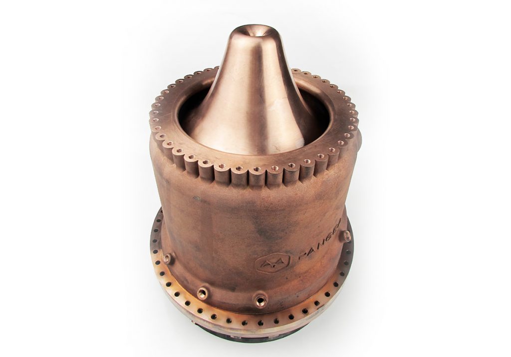
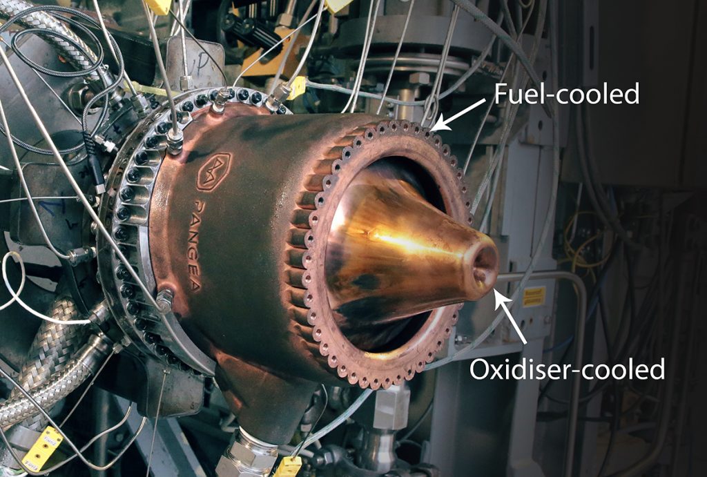
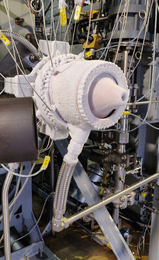
DemoP1, shown in Fig. 4, is the first additively manufactured aerospike rocket engine in the world to be powered by liquid oxygen and liquid methane. “We took advantage of the dual-wall construction, unique to toroidal aerospikes, to split the cooling system in two circuits,” explained Rossi. “The ‘pointy’ end, called the plug or spike (the latter giving the engine its name), is cooled with liquid oxygen (the oxidiser), while the external housing is cooled with liquid methane (the fuel). In this way, the classic drawback of aerospikes becomes an advantage. First of all, we make use of both propellants, that are fed to the engine at cryogenic temperatures (around -170°C), to take away the heat from the structure. Hence, the enthalpy rise of the entire propellant mass flow rate is fully exploited to keep the engine cool.”
“Secondly, the heat exchanged with the engine drives the propellants to a higher temperature, which makes the injection and combustion process more efficient,” Rossi continued. “Combustion efficiency further increases the thrust of the engine. Furthermore, using both propellants to cool the engine means that less energy needs to be imparted to each one of them, relaxing the requirements on the pressurisation system and leading to a lighter structure overall.”

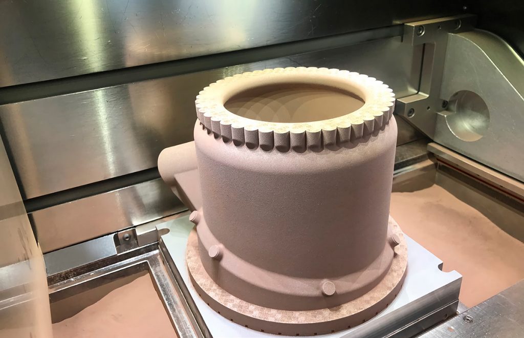
However, tailoring the cooling system to achieve such a feat was no easy task. “Propellants inside the cooling system enter in the liquid state, then undergo a pseudo phase change and leave the channel in a supercritical state. During this process, the properties of the coolant vary sharply, so that taming the fluid to extract the maximum cooling efficiency requires a novel approach for channel design.” In fact, typical cooling channels are traditionally milled in the engine wall in the form of rectangular slots. There are a certain number of channels starting from the base of the nozzle, and their geometry simply follows the engine contour, while changing in width and height.
The geometry of the aerospike does not allow for this simple approach, partly because of its higher heat generation, but also because of its simple geometrical characteristics. Hence, Pangea decided to ‘make a virtue out of a necessity’ and adopted what it calls a pointwise optimisation. “Practically, we optimised every single tiny segment that makes up the channel. This is where Additive Manufacturing shines on DemoP1, because this type of complexity really does come for free in AM; our channels resemble shapes that are found in nature, rather than straight lines,” Rossi said. “The sharp property variation of the coolant requires an equally sharp variation in channel geometry to avoid overcooling or overheating of the material. With our approach, we were able to split the complex cooling problem into many tiny segments and address every single segment for maximum efficiency. This basically means getting close to the material maximum operational temperature at every segment. Whenever you try to overcool the rocket engine, that is pressure that is lost in the channel, hence overcooling must be kept to a minimum.”

“Unfortunately, controlling subsonic fluid dynamics is less straightforward than optimising segments in series, because what happens downstream has an influence on what is happening upstream. Hence, the optimisation process had to be iterated several times and cross-checked with state-of-the-art CFD models. The implementation of CFD analyses allowed us to further play with this virtually unlimited design freedom by introducing roughness and curvature into the equation.”
Because of its geometry and the direction of the coolant flow, the curvature of a classic channel would play a negative role on DemoP1. To mitigate this effect, Pangea introduced artificial curvature on a different plane in the form of a spiral. The spiral shape of the channels on DemoP1 forces the coolant against the walls by centrifugal action, further increasing heat transfer efficiency.

More importantly, roughness, taken alone, is probably the variable with the largest effect on both heat transfer and pressure drop. It is well known that the surface finish of additively manufactured parts can be poor. “If roughness has no purpose in your application, the surface finish must be improved. For us, roughness is of utmost importance to increase heat transfer in the most critical areas. We worked with our partner, Aenium, to modify the roughness level during the build process, as well as exploiting the natural roughness variation of additively manufactured structures by exacerbating the overhang angle in the most critical areas.”
Last, but not least, the first portion of the channel is sized in such a way that the coolant reaches the most critical areas around the so-called pseudo-critical state, where its cooling properties peak in the high-roughness environment.
Design for AM: planning for advanced manufacturing & post-processing
Additive Manufacturing is a relatively new and advanced manufacturing technology with its own unique drawbacks, benefits, and post-processing requirements.
The aerospike rocket engine’s improved performance is achieved at the cost of structural complexity because of the presence of the additional spike structure in the middle of the combustion chamber. Moreover, the rocket engines currently in use are assembled using hundreds or thousands of parts, and therefore have numerous assembly steps, joining operations and surfaces to be sealed. This results in high manufacturing costs and often reduced functionality. Dr Zsombor Sápi, Structural Engineer at Pangea Aerospace stated, “We used Additive Manufacturing and pushed the technology to its limits by integrating all these components into two main parts: the internal ‘plug’, which also houses the injector head, and an external housing. This not only enabled us to simplify the assembly and joining of the engine, but also provided tools to improve other aspects of the structure. We could reduce the weight, fine-tune the load paths acting inside the engine and provide better access to the telemetry system.”
Besides its structural complexity, the thermal management of an aerospike is also challenging. The structure features not one, but two combustion chamber surfaces that are subjected to hot gases and need to be cooled with the same amount of propellant. This demanded the development of a complex system of internal manifolds and cooling channels. The channels have various orientations and cross-sections and are interleaving the structure in a way that conventional subtractive manufacturing processes would simply be unable to deliver.
“Of course, the drawback of the design freedom offered by AM is the constraints set by the Powder Bed Fusion (PBF) manufacturing process. Therefore, the layout of the engine was developed from day one accounting for Design for Additive Manufacturing (DfAM) principles, taking into account the constraints in terms of size and tolerances dictated by design choices and CFD analyses. One of the most important aspects is the necessity of powder removal. This is particularly critical in a rocket engine because a blocked cooling channel can cause the failure of the propulsion system.”
“Several powder removal openings have been integrated into the structure and various post-processing steps and cleaning operations were utilised to ensure the cleanliness of the components. The other challenging field was the printability of overhang surfaces and their correlation with surface roughness. These design constraints set the basis for several iterations between the propulsion (functional) – design – structural analysis – and manufacturing departments of Pangea Aerospace, finally leading to a design ready for printing,” explained Sápi.
Material engineering and GRCop42
Additive Manufacturing processes have been widely used as a rapid prototyping method and cost-effective solution for low-volume serial production, but few people have explored AM’s potential as a tool by which to address the most challenging of metallurgical needs, or considered the benefits AM offers in terms of a new approach from materials engineering.
“In our development of critical TRL9 devices for the space launch sector, we faced numerous material engineering challenges and had the opportunity to solve them through a combination of AM and complex post-processing. The use of nickel alloys such as IN718, IN 625, Invar36, Haynes 282 and Rene 41 is common in this sector, and we internally qualified these materials, all of which demonstrated outstanding performance, in their strengthened condition, when exposed to demanding thermomechanical properties at creep. High temperatures, pressures, acceptable conditions under low Total Mass Loss (TML) outgassing, low Coefficient of linear Thermal Expansion (CTE) and corrosion resistance are some of the advantages of using nickel alloys for space applications. Nevertheless, during qualification they demonstrated low thermal conductivity, preventing full evacuation of heat flux and promoting component failure in its steady state, on top of experiencing hydrogen embrittlement effects,” stated Miguel Ampudia, Chief Innovation Officer at Aenium Engineering.
Copper alloys offer a thermal conductivity twenty times higher than the nickel alloys listed above and experience no H-embrittlement effects, but have lower mechanical properties and are prone to corrosion when exposed to harsh environments. Developed by the team at NASA’s Glenn Research Centre, GRCop42 (CuCrNb) is a complex and advanced alloy capable of surviving high-strength, high-heat flux and harsh environments at high temperatures, making it perfect for regeneratively cooled rocket engines and other applications.
Commonly, the environment and boundary conditions are the factors that place the highest demands on the materials used in a rocket chamber. After supporting complex transitory states, the steady state is defined by high temperatures, extreme thermal gradients, high pressures and direct contact with the propellants and their combustion radicals. For these types of applications, an extra level of awareness is necessary to minimise the material’s exposure to combustion radicals and fully understand plasticity-based cycles.
Pangea and Aenium based all of their qualification procedures and material/process characterisation on the following material properties/behaviours, which represent the main failure factors in these applications:
- Material creep
- Low-cycle thermal fatigue (LCTF)
- Corrosion behaviour
“During steady-state operation, the chamber liners are one of the most challenging geometries in terms of material science. These thin surfaces (less than 2 mm thick) separate the liquid cryogenic propellants, flowing in the cooling channels at a temperature around 100 K, from the combustion chamber, where the temperature exceeds 3000 K. This, in combination with the pressure in the cooling channels, which is higher than 100 bar, and the thermal cycles the material is exposed to, leads to a special temperature-plasticity-based phenomenon called Low-Cycle Thermal Fatigue (LCTF), which is one of the dominant failure modes in rocket engines. In this kind of thermal fatigue, the cyclic deformation is imposed as the result of the constrained differential thermal expansion within a solid caused by temperature gradients induced during alternate heating and cooling in the steady state operation of the rocket engine. For this reason, the microstructure and metallurgical properties of the liners must be specially prepared for a stable cycle, without changing their conditions because of the operating time or cycles.”
As mentioned, GRCop42, when correctly ‘microstructure-programmed’ during processing and post-processing, offers almost stable mechanical and thermal properties, demonstrating better results in this phase than the Ni-base alloys. These, on the contrary, experience microstructure modifications with the thermal cycles induced by rocket engine operation, as well as during the sharp start-up and shutdown transients.
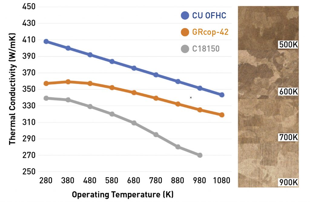
“Additively manufactured and post-processed GRCop42 showed an almost pure copper matrix, yielding excellent thermal conductivity. At the same time, the alloy strength is increased even at high working temperatures thanks to its chromium-niobium intermetallics. Our team led a six-month qualification procedure addressing the most advanced thermomechanical behaviours and establishing multi-parameter procedures for processing and post-processing the alloy under the most demanding certification requirements to meet all of the process needs,” stated Nicola Palumbo, Head of Mechanical Engineering & co-founder of Pangea Aerospace.
“Compared to our other AM-qualified Cu alloys, such as C18150 (CuCrZr) and pure copper (OFHC), GRCop42 demonstrated outstanding thermal conductivity at high temperatures and mechanical properties during creep, maintaining almost stable grain size and strength as opposed to C18150 properties, which decreased with the working temperature.”
Hundreds of different testing probes defined by different ASTM standards in certified laboratory-controlled conditions, and their subsequent analysis, were necessary for the whole understanding of additively manufactured GRCop42 alloy and its definition as one of the ideal materials for the demanding working conditions of a rocket engine combustion chamber.
Processing the aerospike rocket engine using PBF-LB at Aenium
Commenting on the build of the aerospike rocket engine, Miguel Ampudia explained, “The processing and qualification of Cu alloys through PBF-LB can introduce numerous processing challenges. Our teams already possessed extensive experience in TRL9 manufacturing of Cu alloys such as C18150 for flight components on combustion chambers, satellite and launcher applications, but GRCop42 presented numerous challenges that made it necessary to modify the hardware for the process and adopt some new material engineering approaches.”
Aenium’s core business is materials science and complex processing through PBF and other techniques for the space and energy sectors, among others. “Our team developed a method called Multi-volume Laser Energy Density [M-VLED], based on our applied material science knowledge with laser systems and AM. Through this method, using its in-house processing and lab capabilities, our team is able to dynamically modify laser energy density based on the controlled cooling ratios achieved on the powder bed or melt pool.”
“Controlling energy density and cooling ratios accurately enables infinite possibilities around microstructural programming of the part, offering the ability to provide different thermomechanical properties as needed, in just one part. Based on a deep technical study of the alloys we work with, we define the microstructure and its subsequent part properties, achieving changes in specific areas and on specific surfaces without introducing porosity.”
Through this method, it is possible to create or dilute intermetallics and show and hide some phases or microconstituents, which allows the building of a part using multiple process parameters dynamically controlled in specific areas or surfaces where changes to its mechanical/thermal properties are needed. This requires the qualification of multiple M-VLED parameters and special Hot Isostatic Pressing (HIP) strategies during post-processing.
“Depending on the alloy, M-VLED enables us to precisely program parts with multiple areas of yield strength, UTS, elongation at break, thermal conductivity, hardness, surface roughness, residual stress and many others, voxel by voxel.” stated Ampudia. “Creating thermal bridge effects, non-conductive shells, different LCTF behaviours, decreasing part of the post-processing efforts and controlling the residual stress across the part are some of the advantages of using this technique.”
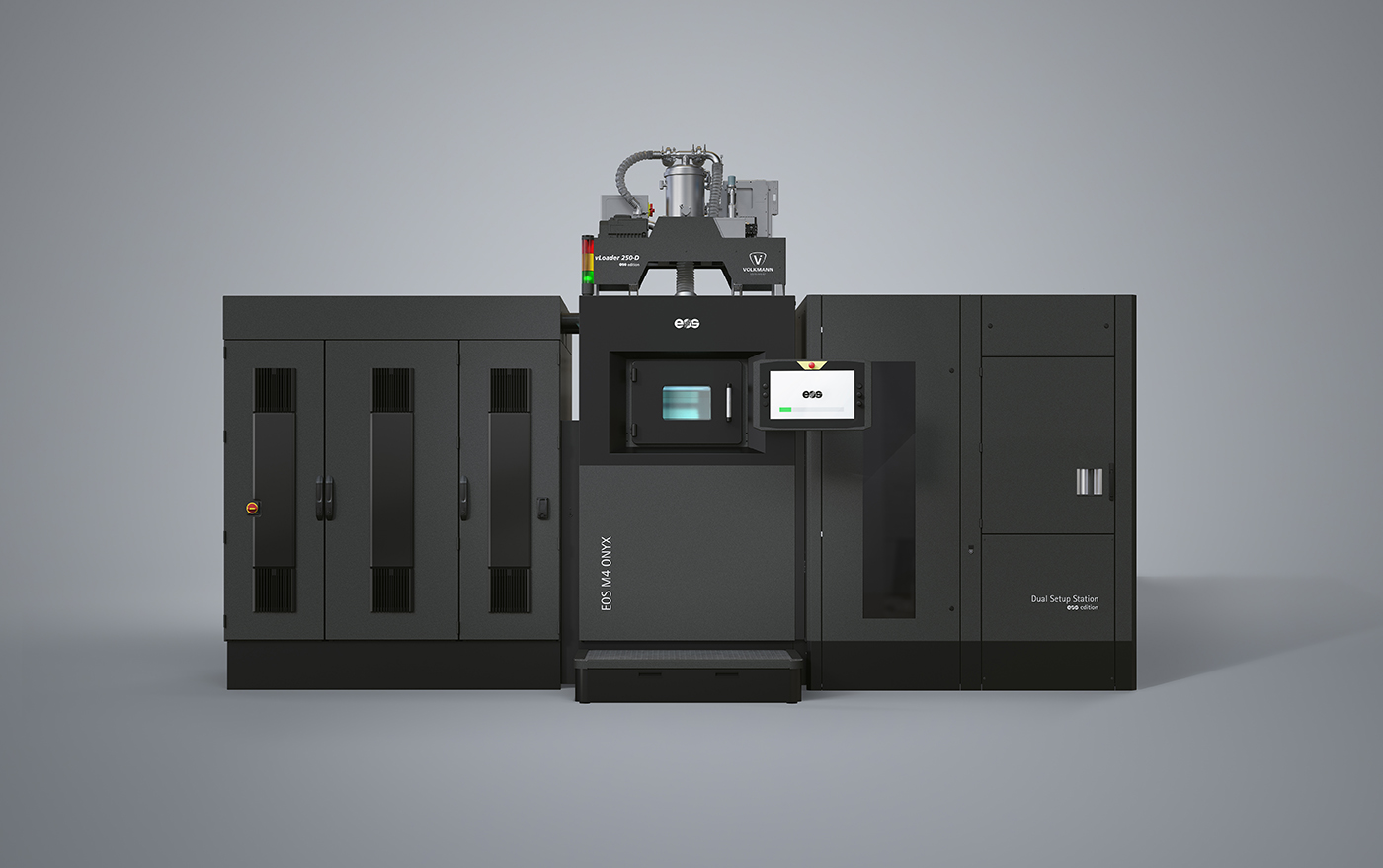
For the whole qualification and production phase, Aenium used EOS PBF-LB machines and numerous types of pre- and post-processing equipment, as well as metallurgy and inspection processes for the powder and the manufactured certification samples. The critical aspects when qualifying GRCop42 for the aerospike’s production were established as:
- Microstructure management and laser control in PBF-LB
- Hardware modifications and special process conditions
- Raw material quality and handling
- Intensive post-processing
“The PBF-LB process introduces a wide range of process variables that determine the metallurgical properties of the final part. Some of these variables are atmosphere, energy density, cooling ratio, layer deposition method, rheology and powder characterisation. The accurate control of all of these variables is what decides the process results. Commonly, process stability changes depending on the area or build plate position. This represents a challenge when applying the M-VLED procedure to control microstructure. It is known that gas flow distribution is not 100% homogeneous across the built plate – even more so in large-format PBF-LB machines – and even laser variables slightly change during a build due to optics and laser module lifetime,” stated Ampudia.

“To apply M-VLED, these factors were precisely measured and controlled in real-time, enabling precise control of the multiple parameters and volumes involved. By achieving high cooling ratios, driven by the energy density applied by the laser and optics, the result of this process decision was to qualify the manufacturing process under He gas in the chamber. This demonstrated better results, improving the management of Cr2Nb precipitated elements compared with Ar atmosphere.”
The build plate was precisely studied to avoid diffusion problems on the first layers, and enhanced thermal control and heat distribution was achieved using a special platform that remains confidential. Powder distribution on the build plate and its flowability also represented some challenges. Particle distribution was tested and parameterised, and finally defined through different batches, but, even then, the best results were obtained when modifying the recoating system to increase flowability, using thermal methods that currently remain confidential. These modifications were required to increase the stability and homogeneity of the process.
“As important as the defined pre-processing and AM processing are, this study also required detailed and accurate post-processing. Some challenges were presented by the need to maintain the desired microstructure despite extensive post-processing requirements that included high-pressure cycles, thermal cycles and other chemical and e-chemical methods for roughness treatment over the aerospike’s channels and injectors,” concluded Ampudia.
After these R&D, testing and qualification procedures were complete, the alloy and process were ready for the first component to be built, certified and enter production.
Post-processing the rocket engine
The inaccessibility of the unique cooling channels in the aerospike rocket engine meant that a different approach to depowdering was required. Pangea and Aenium used the most advanced techniques to be sure the final dimensions were compliant with requirements. Using this information, the liner, the most critical part of the engine, was accurately machined.
Nicola Palumbo explained, “One of the biggest challenges presented by AM when it comes to designing a single-piece part with integral features such as cooling channels and liner, inlet and outlet manifolds, sensor ports, attachment flanges and stiffening supports, is the removal of powder entrapped within the channels during the AM process, as no access to the interior is available. This is important because, as already mentioned, no residual powder is permitted by the rocket engine requirements. The same is valid for chips, burrs and scrap material produced during machining, polishing and corrosion protection post-processing; if not removed, they could be detrimental and lead to the failure of the engine during the firing. Moreover, the cleaning itself must not contaminate the engine or reactivate any corrosion mechanism.”
“Given the inherent geometric complexity of an aerospike engine and its extremely complicated cooling channels, it is no trivial matter to achieve this goal in a simple, efficient, inexpensive and feasible manner. And, more seriously, failure to do so could result in a showstopper,” stated Palumbo.
“To be sure that no debris is left in the engine after post-processing, a particular system of evacuation channels and ports, with the minimum number of operations possible, has been designed for both the external case and the plug. These were designed into the part from the beginning to the very end of the manufacturing process, proving that if ‘Design for AM’ is correctly approached from the very beginning, even the most challenging projects can be achieved by implementing relatively easy operations.”
The liner is one of the most important parts of a rocket engine, as it allows the proper thermal exchange between the hot gas side and the coolant side, preventing the construction material from melting down. This is possible only if its final dimensions and surface roughness are compliant with very tight requirements. It is well known that one of the drawbacks of AM is that the production of ‘perfect’ parts is impossible, due to the distortions that occur during the building of the part and the poor surface roughness when compared to other manufacturing methods.
Palumbo stated, “This usually leads to the production of a liner which does not have a uniform thickness, with differing material distribution along the part presenting multiple crack initiation sites all over its surface. At Pangea Aerospace, we designed the aerospike keeping in mind, from scratch, this important requirement. To overcome this problem and create a uniform liner, the parts went through a series of post-processes involving CAD-CAE-3D scan-Computed Tomography that ultimately resulted in a very accurately machined part within the tight tolerances required. This was made possible thanks to an initial design effort considering all processes in the production chain, which enabled the post-processing of the engine without the need for expensive tooling, reducing cost and lead time. This again confirms how Additive Manufacturing is the perfect candidate for a complex engine like the aerospike.”
Test firing demonstrates aerospike rocket engine’s viability
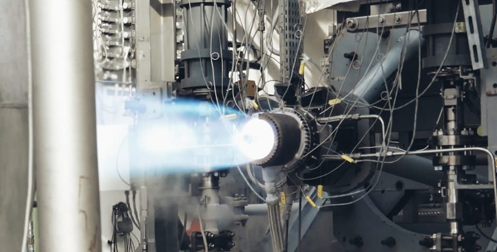
The DemoP1 aerospike rocket engine was tested at the P8.2 high-pressure facility in Lampoldshausen, Germany, one of the few facilities in the world capable of testing methalox rocket engines of this size. The test campaign was performed over a span of one month, totalling seven cold-flow checks and ten hot runs. Cold-flow checks are extremely important for an additively manufactured part of this complexity, because the AM process still has limited repeatability compared to the standard processes used to produce rocket engines. Hence, the hydraulic resistance of the entire thrust chamber needs to be carefully characterised before moving to the hot fire phase.
Federico Rossi commented, “Hot runs have been performed in incremental steps, starting from the classic ‘burp’ test and concluding with three consecutive runs of more than one minute, with the last hitting 160 seconds. The first short runs were useful for characterising the initial transient and tune the timing of valve openings. In total, there are six valves onboard the engine that control the mass flowrates of the main propellants and of the propellants for the ignition system. These had to be carefully timed to obtain a smooth but fast start-up and to ensure survival of the ignition system during operation of the main combustion chamber. The latter runs were full-duration steady-state tests, useful to ensure repeatability of the combustion process and investigate how the engine’s structure and performance react to changes in the design parameters. The rocket engine has been tested across and outside its design operational envelope, changing feed system parameters ‘on the fly’ during the same hot run.” Fig. 12 shows an aerospike rocket engine in steady-state operation.
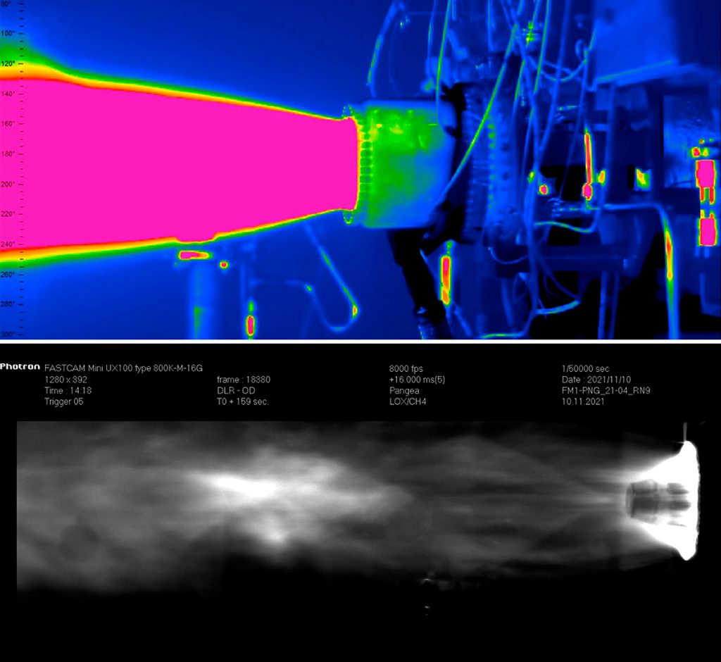
One of the most important takeaways from the rocket engine test campaign was the characterisation of the engine’s reusability. For this reason, it was fundamental to monitor the engine wall temperature through the different firing cycles (cold-hot-cold), triggering low-cycle fatigue: the main mechanism responsible for early rocket engine failure. The vital parameters of the engine were monitored with pressure and temperature sensors, together with a thermal camera whose output is shown in Fig. 13.
The next stage of the aerospike rocket engine’s journey
Leveraging the technologies demonstrated during the development of DemoP1, Pangea Aerospace is starting the development of our first commercial engine, named Arcos. This uses the same architecture and materials as DemoP1, but with a massive increase in dimensions and performance. “Arcos will bring the aerospike concept to its full potential by adopting a very large expansion ratio, maximising performance and compactness by allocating the turbopump assembly (TPA) inside the toroidal aerospike,” stated Rossi.
The project partners are also researching advanced microstructures for corrosive and demanding boundary conditions using nano-alloyed GRCop-42 Cn-Ts. “We have clearly demonstrated the advantages of using material science as an innovation driver for the space sector, and the GRCop42 alloy has been established as one of the most challenging and interesting alloys in the market for addressing the boundary conditions offered by regeneratively cooled rocket engines. Nevertheless, our consortium is now focused on carrying all these innovations to the next step at TRL9, with the first commercial aerospike Arcos developed by Pangea Aerospace. Aenium will bring to the consortium the next level of materials engineering through the development of multi-material chambers,” stated Miguel Ampudia.
“By combining the excellent and proven properties of GRCop42 alloy, the performance of nickel and a third refractory alloy, the consortium is now developing the next techniques and procedures for achieving bimaterial and trimaterial interfaces, providing the combustion chambers with the best properties of each material alloy by volume, all of which will have M-VLED techniques applied to them. The coming months will also bring to light new alloys as a focus for development, based on the collaboration agreement achieved by Aenium with one of the most innovative powder brands in the USA; Powder Alloy Corporation, Ohio, which will bring to the consortium the most advanced methods for creating new performance alloys ready for processing, developed ad-hoc to suit the needs of the multi-material parts.”
Currently, both teams are obtaining the first qualification process and material results as a starting point for the next generation of rocket engines with the technology that will bring into life the first commercial aerospike rocket engine flying, achieved through the intelligent combination of Additive Manufacturing and material science.
Contact

LAST MONTH’S MOST-READ ARTICLES