Hybrid inserts for mould and die production: How workflow optimisation can help make the business case for AM
The use of metal Additive Manufacturing for the production of injection moulding tools that have been optimised by conformal cooling is growing internationally. For many companies, however, the main obstacles to adoption are not concerns about material properties or apprehension about unfamiliar processes, but simply initial cost - the tooling industry is extremely competitive and AM inserts can be expensive. Here, 3D Systems’ Mark Cook and GF Machining Solutions’ Dogan Basic present a case study from leading toolmaker and injection moulding specialist TK Mold that highlights how such inserts, when efficiently manufactured, can reduce overall manufacturing costs and improve part quality. [First published in Metal AM Vol. 6 No. 3, Autumn/Fall 2020 | 20 minute read | View on Issuu | Download PDF]
Injection moulding is, without a doubt, one of the most widely-used and successful manufacturing processes. It is most commonly applied to the production of thermoplastic and thermosetting polymer parts, using moulds manufactured from steel alloys, which allows for, in many cases, millions of injection cycles in serial production. The process entails injecting molten material into a cavity shaped like the final part, followed by rapid cooling to ensure hardening. The cooling time must, however, be sufficient for the part to properly solidify so it can be ejected with limited deformation. The cooling aspect of the injection cycle is, therefore, a key factor in achieving high-quality parts while keeping the cycle time efficient. Cooling of the mould insert is achieved by circulating a cold fluid (typically water or oil) through the mould to cool the mould surface.
Additive Manufacturing has proven to be a valuable solution for the optimisation of the cooling process, because it allows for the creation of cooling channels that closely follow the moulding surface – this is known as conformal cooling. These moulding surfaces can be highly complex and are therefore difficult to cool. AM enables the design and manufacture of parts that incorporate cooling channels that would be impossible to produce using conventional manufacturing technologies.

With AM, cooling channels can be set at a constant distance from the surface of the part to achieve uniform cooling, and deliver two main advantages:
- Cooling time can be reduced due to more efficient heat dissipation, which reduces the time required to harden the part
- The part will cool uniformly, preventing the warping and deformation that can arise from an uneven temperature gradient
Although the benefits of AM for efficient cooling are well-documented and have often been presented, adoption has been slow due to initial concerns about material properties, costs, and a lack of knowledge on how to apply the technology in a market segment that is often regarded as quite traditional. In addition to the fact that mould makers are often risk-averse, they are generally under tremendous pressure to manufacture injection moulds at the lowest price possible. The use of additively manufactured inserts in moulds offers significant benefits, but also comes with additional costs. Mould manufacturers must, therefore, demonstrate the value of the additional investment to the final customer. This is clearly illustrated by the fact that adoption of conformal cooling has been higher in companies which manage both mould production and injection moulding. These companies fully understand the value, and actively incorporate AM into their manufacturing workflow, demonstrating return on investment (ROI) and increasing their use of the technology as they further master the process.
The importance of technology integration
While the adoption of AM is increasing, many manufacturers are still reluctant to take this step. One of the biggest challenges in using AM is the need to integrate the new process into manufacturing workflows built on well-established, mature manufacturing technologies. In particular, in the mould-making segment, additively manufactured components and inserts require – in nearly all cases – additional subtractive machining operations to achieve the very high surface quality required on the mould surface.

As a result, manufacturers expect metal AM providers’ solutions to cover the complete workflow, from design to final part, to deliver moulds that meet precise specifications. Software, AM machines, materials, subtractive technologies, automation and clamping solutions must be combined to provide an efficient ecosystem to drive down costs and complexity.
Rethinking mould design with AM at TK Mold
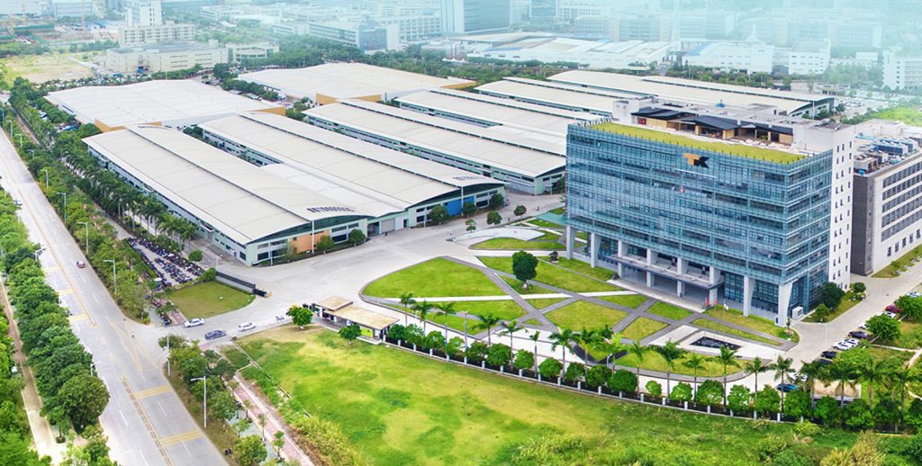
To demonstrate the benefits AM can bring to the injection moulding process, this article reports on how TK Mold, a customer of GF Machining Solutions’ subtractive and additive systems headquartered in Shenzhen, China (Fig. 1), is using Laser Beam Powder Bed Fusion (PBF-LB) technology and, specifically, how workflow optimisation was able to support the business case for AM mould inserts with conformal cooling.
Established in 1983, TK Mold is a subsidiary of TK Group (Holdings) Limited, a well-regarded manufacturer of plastic moulds and parts for a variety of industries including healthcare and consumer goods. TK Mold manufactures plastic moulds and parts for mobile phones, healthcare applications, smart homes, packaging and precision electronics. In addition to its Shenzhen base, TK Mold has three other factories in Suzhou and Huizhou, China, and Braunschweig, Germany.

With thirty-seven years of mould design and fabrication experience, the company is dedicated to providing the best performance injection mould solutions and final plastic parts. As both a mould maker and a parts producer, the company quickly grasped the advantages of metal AM and invested in it to develop mould inserts with conformal cooling channels. TK Mold’s mould-making and injection capabilities uniquely position the company to benefit from using these inserts to produce final parts – the benefits include productivity and quality gains, as well as the ability to deliver more efficient solutions to its customers.
TK Mold applies AM to produce mould inserts where conventional subtractive machining is unable to achieve the necessary quality and productivity at a reasonable cost. The example presented here is common in the packaging sector – particularly for products linked to the information and communications technology (ICT) industry. Used as an element of the packaging box of a smartwatch, the plastic part is the support for fixing the watch inside the box (Fig. 2).
As the part is produced in large series, the packaging and the support must also be produced in large series. The challenges therefore relate to cost and productivity. As the final product is considered a high-value item, there are also requirements in terms of the support’s aesthetics.
The challenges of this type of packaging component are quite common, and the number of similar applications is infinite. Concerning this application, TK Mold faced three critical manufacturing challenges:
- Productivity targets and minimum cost per part could not be reached with conventional mould insert manufacturing processes
- Non-conformal cooling channels resulted in suboptimal thermal regulation
- Costly assembly of mould insert components was required to improve the cooling via traditional manufacturing methods
To improve the process, TK Mold’s engineers focused only on the improvement of the most critical mould inserts: those with the most influence in terms of cycle time or part quality. This is where the ROI in metal AM is the highest.
Efficiently integrating AM in the manufacturing process of a mould insert
GF Machining Solutions and 3D Systems have partnered to develop an end-to-end solution that enables manufacturers to more efficiently produce complex metal parts. This is accomplished by seamlessly integrating metal AM into existing manufacturing processes through the development of an optimised workflow. Here, each step of the workflow is illustrated as it applies to the custom solution created for TK Mold.

Design
Through the adoption of AM, new design possibilities are available to mould manufacturers. Such design freedoms must be mastered, bearing in mind both the layer-by-layer manufacturing approach as well as the raw material involved in the process – the fine metal powder. These two elements result in a very limited set of constraints to the part design, mainly related to overhang regions, feature size and ease of powder removal. For additively manufactured parts with conformal cooling channels, such constraints may be easily overcome by adhering to a few design guidelines, which have become well-established over the years.
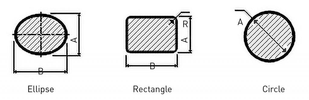
First, the size and shape of the internal channels have design constraints. Large overhanging regions require support structures that are impossible to remove from the inside of the part after Additive Manufacturing. Channel diameters are thus constrained in size and self-supporting channel shapes (such as diamond, elliptical, or teardrop, among others) are preferable to the traditional round cross-sections typical when straight-drilled holes are used by traditional methods (Fig. 3).

Additionally, some traditional design considerations for the mould-making sector are still valid in the case of additively manufactured moulds and dies. These mainly concern the minimum distance of channels from part walls for structural resistance, as well as the pressure drop throughout the whole channel path, and ease of cleaning (both mostly influenced by the channel section size, path and number of branches). Leakage is not an option. In these cases, the minimum distance should be large enough to safely process and post-process the mould. Thus, from the design phase, risks can be greatly reduced.
The generation of conformal cooling paths in adherence to the above design guidelines may quickly become very time-consuming with traditional computer-aided design (CAD) software tools. For this reason, a dedicated software solution such as 3DXpert®– and particularly its Additive Moulding Add-on – is very helpful for mould designers and tooling manufacturers in optimising part quality and reducing design and manufacturing costs.
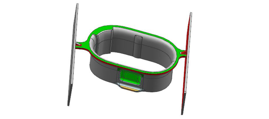
This add-on makes it possible to create conformal cooling inserts and to combine traditional and conformal cooling where appropriate (Fig. 4). This is made possible by a unique set of functionalities that save the user hours of design work before moving to the simulation-based verification and validation stages of the mould design:
- Automated as well as manual generation of the conformal cooling path – essentially generating the channel path based on a set of input data from the user
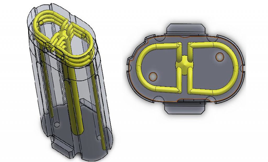
- Easy and fast creation of channel geometry (Fig. 5)
- Analysis of channel overhang areas
- Analysis and optimisation of channel distance from part walls
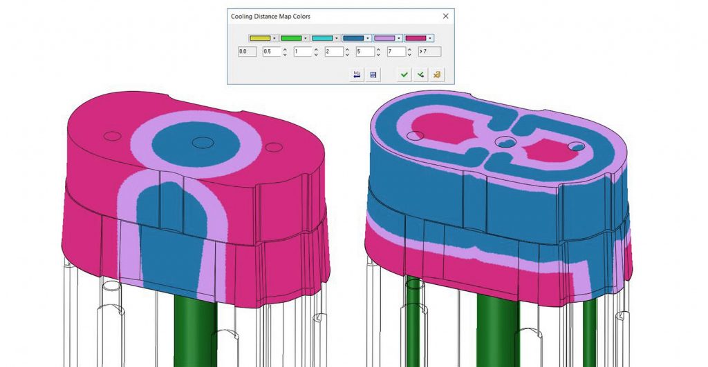
- Colour map of channel distance from active surfaces
3DXpert includes tools such as the ‘heat map’, which allows designers to quickly evaluate the homogeneity and efficiency of the cooling. This does not replace more complete rheology simulations, but allows the user to quickly assess the design quality early in the process.
Simulation
Before starting to build a mould insert in an AM machine, performing rheology thermal assessments is often done to detect where potential issues may arise. This makes it possible to interpret whether the optimised channels will be effective, particularly whether there is a need to improve the temperature homogeneity to reduce hot spots (Fig. 6).
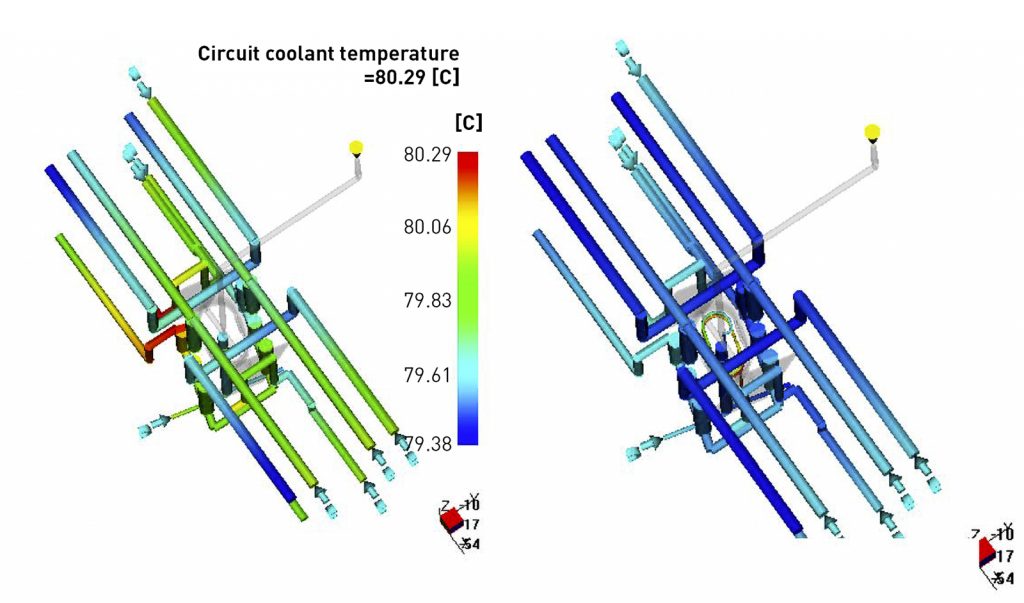
In Fig. 7, we can observe the temperature inside the ‘outer channels’, which transport the coolant in the insert. In this image, the latter is located in the middle in a grey colour. We can already see a colder temperature inside the channels, but also more homogeneity between the conventional approach and the conformal approach.
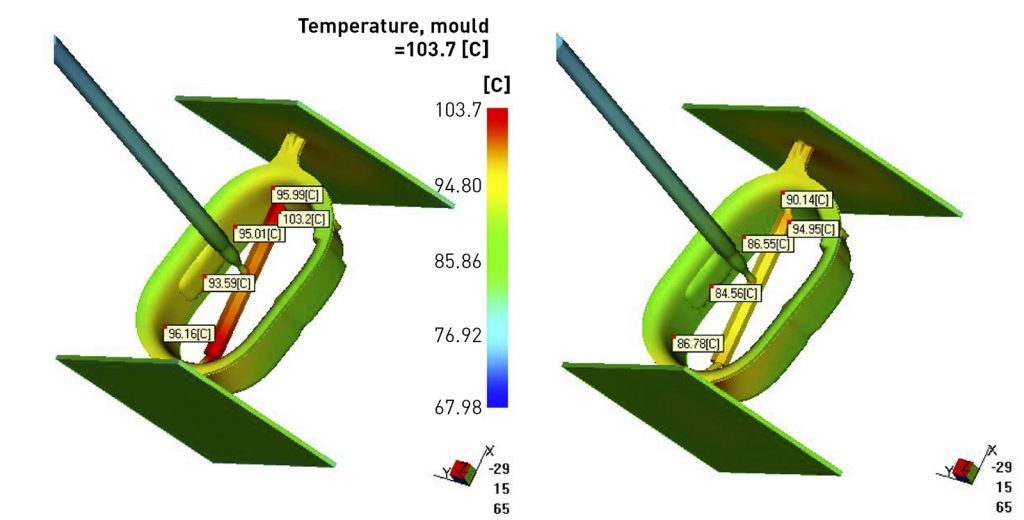
In Fig. 8, we can analyse and compare the potential hot spots during injection with or without conformal channels. Here again, we observe a decrease in the temperature of the hot spots, going for example from 96°C to 86°C. Most important is the much more even temperature gradient, which is the critical factor influencing the quality of the part in terms of warpage and distortion. In this specific case, a productivity increase is the main goal, but customers are always looking for quality improvements.
Today, these simulations are more reliable as rheology models have improved, taking cooling geometries into consideration; this type of data was previously not easy to simulate.
The simulation tools allow the designer to better predict the real-life efficiency, and thus more confidently design, the conformal channels placed inside the mould insert. It theoretically validates that the channels will have a positive impact on the injection process and, ultimately, on the plastic part. TK Mold uses these types of tools to demonstrate the added value of conformal cooling to its customers (internal or external) before the manufacturing of a mould.
Hybrid manufacturing
While AM technology is helping many companies in the mould and die sector achieve new cost savings and efficiencies through conformal cooling, the economic viability of many applications requires other approaches. Indeed, for structural reasons, these applications typically include parts that require large amounts of mould material – in the case of AM, metal powder. This can make large parts costly to manufacture, as an AM insert’s price will be directly linked to the volume of material required for the AM process.
To overcome these challenges and find ways to profitably integrate this new technology into their operations, manufacturers can pre-machine a so-called preform and then, using AM, produce a portion of the part with value-added features in the location where the technology can prove most beneficial.
In addition, when using AM directly on a section of the final machined geometry, the costly cutting operation needed to remove the insert from the build platform is eliminated. This combination of subtractive and additive technologies – which is proving cost-effective – results in what is now commonly referred to as a hybrid part.
Unlike many AM applications, here the manufacturing process begins with the machining of the preforms. In this case, the outer geometry of preform is typically produced by cutting a blank plate with wire electrical discharge machining (EDM). Ejection holes and cooling channels are, on the other hand, previously machined in the blank by deep-hole drilling. It is crucial that all preforms are identical in terms of height, since the Additive Manufacturing process must be conducted on a level plane.
Beginning the process with subtractive machining, however, introduces new positioning and referencing challenges. This type of hybrid process must therefore start with the preform fixed on the build platform before the intended AM section is aligned by using a referencing system. The use of this type of referencing is especially challenging because, unlike in CNC machining, in an AM machine there is no physical link between the optics and the target substrate.
Instead, manufacturers generally have to rely on visual alignment or external coordinate measuring machines (CMMs) to confirm positioning accuracy. Both techniques are time-consuming and, in the case of simple visual alignment, prone to operator error. With variances in excess of 100 µm, these techniques are also unable to provide the accuracy required for most final applications.
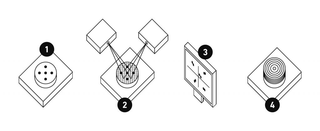
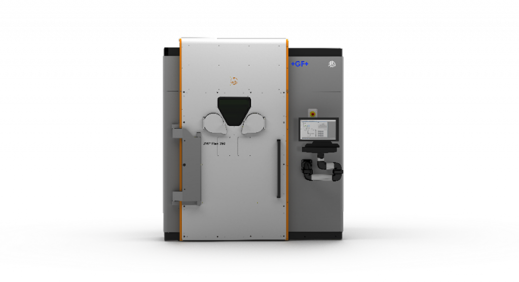
To overcome this issue, GF Machining Solutions and 3D Systems have developed a software solution that leverages the power of the meltpool monitoring hardware available on the partners’ DMP series of metal AM machines. In machines such as the DMP Flex 350, DMP Monitoring in-process monitoring software acquires meltpool data during the build process to detect potential defects such as lack-of-fusion pores.
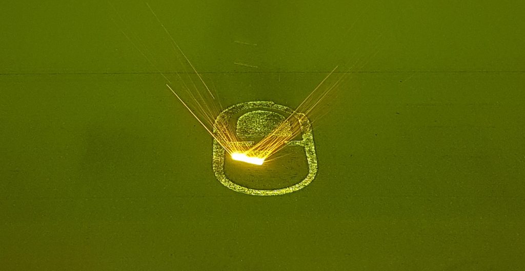
The DMP Calibration tool function exploits this light-sensing monitoring hardware for another purpose: scanning preforms to identify pre-machined locating holes in the part surface. The contrast in light reflection between the part surface and such holes allows for an extremely reliable method of establishing the precise location of the preform on the build platform (Fig. 9).
With user-defined threshold values, this referencing process offers exceptional repeatability and accuracy without any risk of human error. Furthermore, the use of the laser enables the referencing of multiple parts on the same build platform in a single operation, further accelerating high-volume production. Thanks to this optical system’s exceptional level of accuracy, the final quality of the referencing operation, and thus of the resulting hybrid parts, is higher as well.
Lastly, the use of dedicated tooling and fixtures, such as those from GF Machining Solutions’ System 3R unit, allows the hybrid parts built in the DMP machine to undergo all the necessary post-processing operations with reduced setup and changeover times, thanks to the standardised part interfaces being compatible with multiple machines.
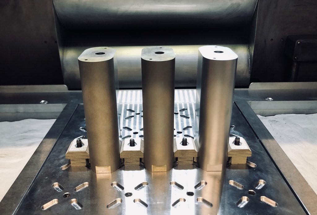
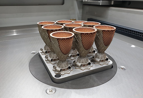
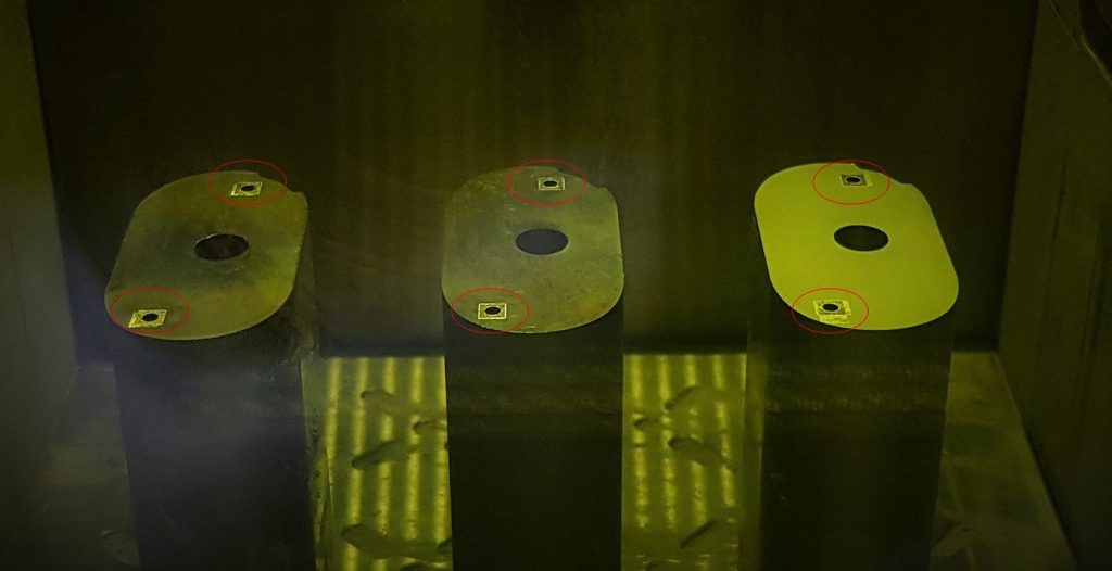
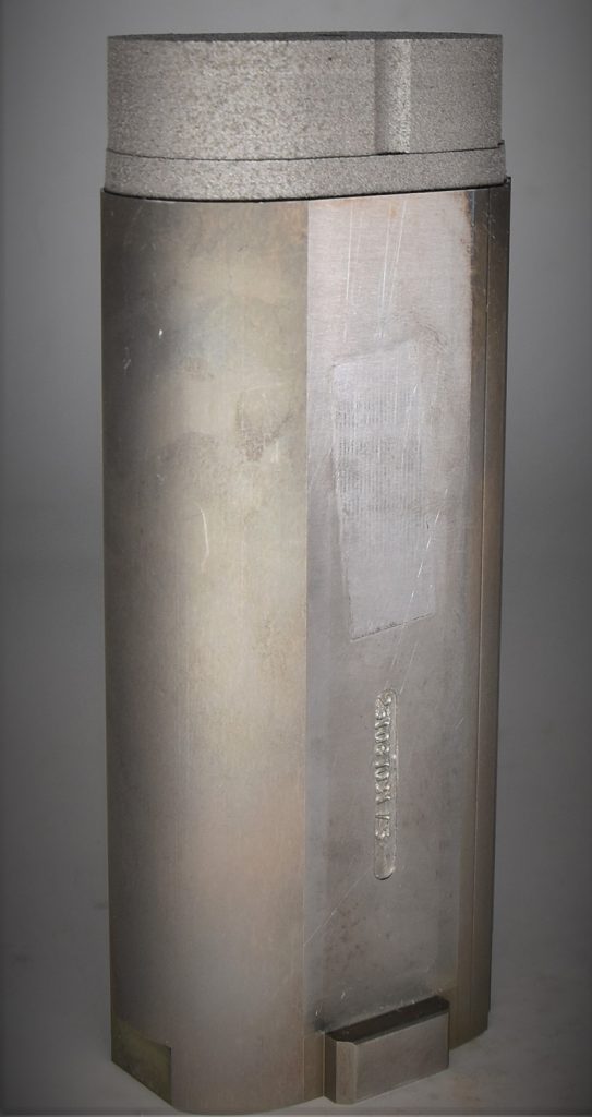
TK Mold uses the above-described process and equipment to produce high-quality hybrid parts, and manufactures around 90% of the moulds requiring AM-enabled conformal cooling by this method. As an example, the hybrid mould insert object of the smartwatch packaging support was achieved from a preform obtained by wire EDM in two different positioning steps. Each preform was then clamped onto the System 3R interface plate ‘AM Carrier’, mated with the DMP machine (Fig. 10). Here the DMP Calibration tool was exploited to correctly reference each preform independently through its set of two locating holes, automatically calculating and applying both translation and rotation corrections to the job file (Fig. 11).
As a last step, the AM build was performed in 3D Systems’ LaserForm® Maraging Steel – a proven material for the mould and die sector thanks to its wear resistance – on a DMP Flex 350 machine.
Surface and sub-surface porosities are particularly critical for mould and die applications, as they may emerge on the part cavity walls after their subsequent machining, leading to defects on the moulded product; moreover, they may be greatly detrimental for the lifetime of the mould/die, constantly undergoing thermal fatigue while being in operation. Thanks to a finely tuned laminar argon flow, the DMP Flex 350 ensures a high removal rate of fumes which are the main driver of inconsistent density (Fig. 12).
Post-processing
Once the part is built (Fig. 13), final machining operations are required to achieve the expected surface roughness on the final geometry. A first programming stage is performed to generate the tool path for the surface finishing of the required area. A real benefit here is 3D Systems’ Cimatron® software, which provides the technology user with a seamless transition between AM and post-machining.
Once the program is ready, the insert is clamped inside a Mikron MILL S 400 U Milling machine from GF Machining Solutions. This product is well-established in the mould-making industry and enables a perfectly homogeneous surface finish. The excellent mould surface quality is particularly valuable for plastic parts with a final transparent finish, where flaws can be easily visible. Mirror surface finishing also reduces the need for hand polishing of mould components, reducing lead time. The square sections of the ejector pins required a milling operation (3+2 pre-machining) and a final grinding operation.
Improved efficiency and productivity with lower total cost of operation
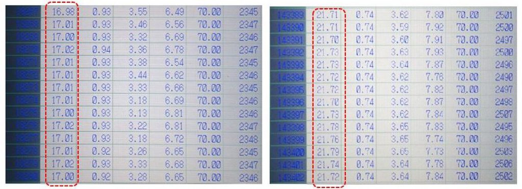
Once the optimised insert is finished, it replaces the conventional insert inside the mould, and the injection process can begin. This article’s observations focus on two elements: cycle time and part quality. The first element influences productivity and the second element influences waste costs.
The injection data collected in Fig. 14 show that the total injection cycle time varies between 21.70 and 21.79 seconds with a traditional insert. With the optimised insert, the cooling time of the plastic is reduced and cycle times stabilise between 16.98 and 17.01 seconds. This represents a significant cycle time reduction of 22%.
The consequences of this productivity gain are multiple. TK Mold was able to increase its production from 189,788 pieces to 242,250 pieces produced per month, equating to an increase in monthly revenue from this application of RMB 92,871, or approximately €12,000.
Additional considerations are the cost savings that are available due to improved productivity by reducing the hourly cost of machine use and increased flexibility in terms of machine capacity. Due to the improvements in thermal homogeneity and the reduction or elimination of hot spots, TK Mold also improved repeatability and final part quality, thereby reducing these waste costs while better satisfying its end customer.
Such a solution can also help companies to meet demand without needing to invest in additional new moulds. According to TK Mold, the ROI on the production of this insert by AM is very attractive and, in this specific case, was achieved in fewer than twenty-six days of production.
Considering that this case represents just one application, and that TK Mold can use this technology for many moulds and produce them at multiple locations at the same time, AM is very quickly paying for itself. As a result, TK Mold is now operating its AM machine at a very high capacity, in order to meet the demand for various optimised inserts.
Conclusion
By enabling the generation of conformal cooling paths within inserts, the adoption of AM in the mould and die sector has repeatedly been proven as an effective way to enhance the yield of moulding processes in terms of both productivity and part quality. This is confirmed by the application case study from TK Mold, and its now firmly established use of AM mould inserts in everyday production.
Moreover, as this case study demonstrates, for companies to fully grasp the end-to-end value offered by this disruptive manufacturing technology, and thus quickly achieve ROI, AM should not be evaluated as a ‘stand-alone’ process. For the technology to shift to the full industrial scale, its integration with conventional, well-established manufacturing processes is crucial; a complete workflow approach, from design to final part, is required.
Thanks to their expertise in multiple fields and processes, GF Machining Solutions and 3D Systems are able to offer industrial solutions that make this possible. Their joint offering is further enhanced by the availability of dedicated products and tools, such as the Additive Molding module of 3D Systems’ 3DXpert software for the design and analysis of conformal cooling channels, and the DMP Calibration tool offered with the DMP machine series for the manufacturing of hybrid parts through the automated, user-error-free alignment of preforms and substrates to the highest accuracy inside the AM machine.
In conclusion, for the mould and die as well as other sectors, a whole ecosystem has to be considered, encompassing software, AM and subtractive machines, materials, automation and tooling solutions. These must be efficiently combined and integrated to drive design and manufacturing costs down, thus allowing AM technology to express its full potential as an industrial process.
Authors
Mark Cook
Vice President, Metals Products
3D Systems
www.3dsystems.com
Dogan Basic
Product Manager
GF Machining Solutions
www.gfms.com

LAST MONTH’S MOST-READ ARTICLES