


From silicone and rubber to steel and ceramic: the weird and wonderful world of wipers
In powder bed Additive Manufacturing processes, the recoater system is responsible for spreading a fine and even layer of powder for each layer of a build. This system typically uses wipers to create the necessary surface, with the variants of wipers used being almost as diverse as the number of AM machines on the market. Olaf Diegel and Terry Wohlers explain why it is not only machine operators, but also designers and engineers, who need to be aware of the weird and wonderful world of wipers. [First published in Metal AM Vol. 5 No. 4, Winter 2019 | 10 minute read | View on Issuu | Download PDF]
The process of setting up a metal AM build job can be complex. Though it is rare for engineers and designers to be directly involved with the manufacturing of parts, in Additive Manufacturing they can greatly benefit from hands-on operation of machines; largely because it gives them a much better idea of the variables and complexities involved. If the designers of the parts to be built are not directly involved with the build job, it is critical that they at least have a good dialogue with the machine operators to ensure good results and met expectations.
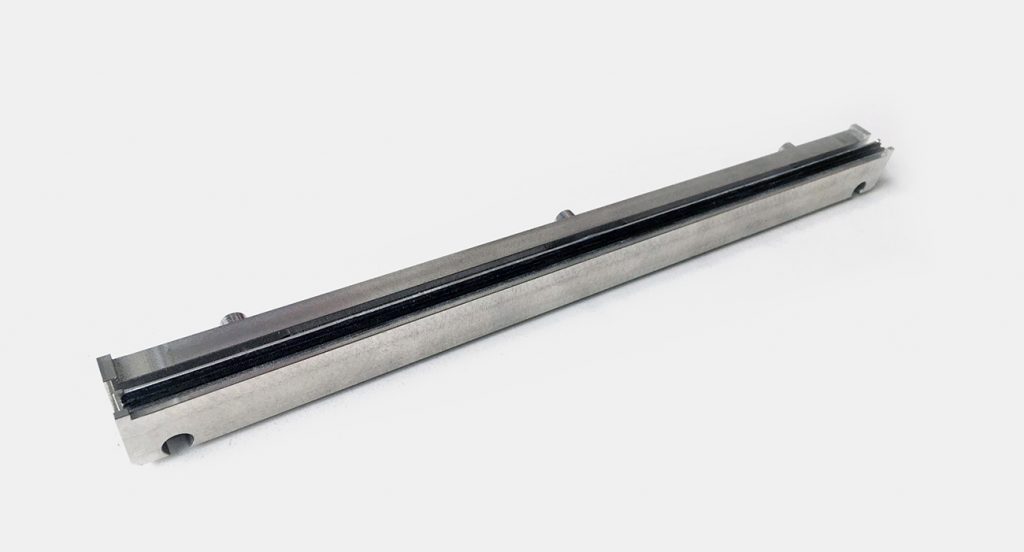
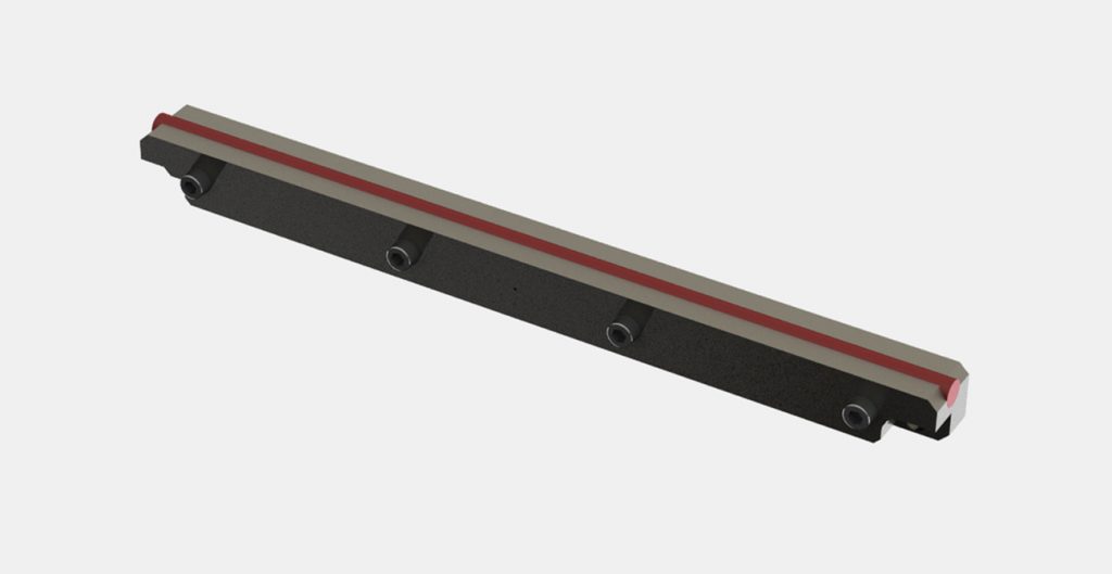
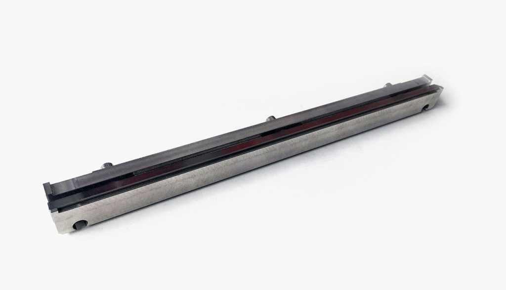
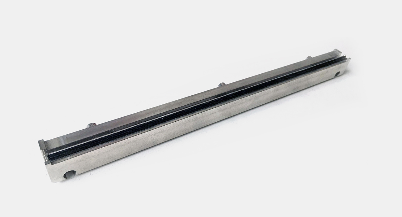
On most metal AM systems, the building of parts occurs on a build plate. This plate can be either square or round, and is bolted onto the build chamber piston, which moves down by the thickness of a single layer after the completion of each melting operation. The powder is spread over the build plate in a thin layer by a recoater system consisting of soft silicone, rubber or carbon fibre brushes, a hard steel or ceramic wiper blade, or a hard roller. Different types of recoaters have advantages or disadvantages depending on the application.

Soft recoater blades
Because soft recoater blade material is flexible, this type of recoater is more forgiving when processed metal distorts and protrudes out of the top of the powder bed. In cases where a hard recoater physically crashes into protruding metal and halts a build job, a soft recoater may permit the job to complete, although with a potential imperfection at the point where the wiper has to flex to avoid a collision. Soft recoaters become damaged more easily, however, and typically need to be replaced after every job. Wipers that use a round silicone profile instead of a rectangular one must be rotated after every job.
Soft recoaters are ideal for the Additive Manufacturing of a range of different parts at once, and for building particularly delicate parts. In a batch of different parts, even if one part happens to deform to the point where the wiper is deflected, the other parts will be unaffected, and the build will not need to be stopped.

Hard recoater blades
A hard recoater, whether a flat blade or roller, exerts more pressure on the powder than a soft recoater and allows for little part deformation. If a part deforms by more than a layer thickness of 20–80 µm (0.0008–0.003 in), the machine is likely to crash. This means that when the recoater hits the part that is protruding from the powder, the build stops. Alternatively, very fragile parts break off and are dragged across the powder bed.
Hard recoaters are ideal when identical parts are built on the same build platform, and the part has been tested to build without any major vertical deformations. If one part in the build deforms, the chances are that other parts in the build will also deform.
A hard recoater is not necessarily better or worse than a soft recoater. It is important to understand the nature of the parts being built and to choose the best recoater blade for the job.

General part positioning guidelines
How one positions the parts on the build plate can also have a major impact on the success and quality of the built parts, as well as on the lifespan of the recoater blade. As a recoater spreads a new layer of powder, the sections of the part that have been built should not move. If any distortion of a part occurs (however minute), it can exert mechanical force on the recoater. This force can be sufficient to bend or break the part, especially when features are delicate. If the part distorts but does not bend or break, it can be enough to crash the recoater, causing a build failure and/or damage to the recoater blade.
By correctly positioning parts on the build platform, one can minimise the amount of force the parts exert on the recoater. This can reduce or eliminate failed builds.
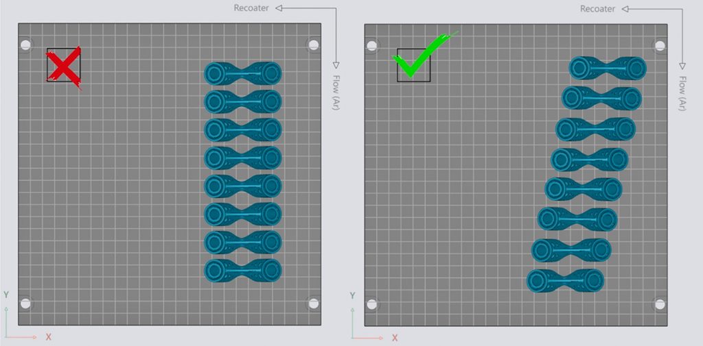
If a part is largely rectangular or contains long, flat walls, avoid positioning parts with long walls parallel to the recoater. This could cause the recoater to suddenly meet a large obstacle. Instead, rotate parts around the vertical Z axis to minimise the recoater force at any one point.
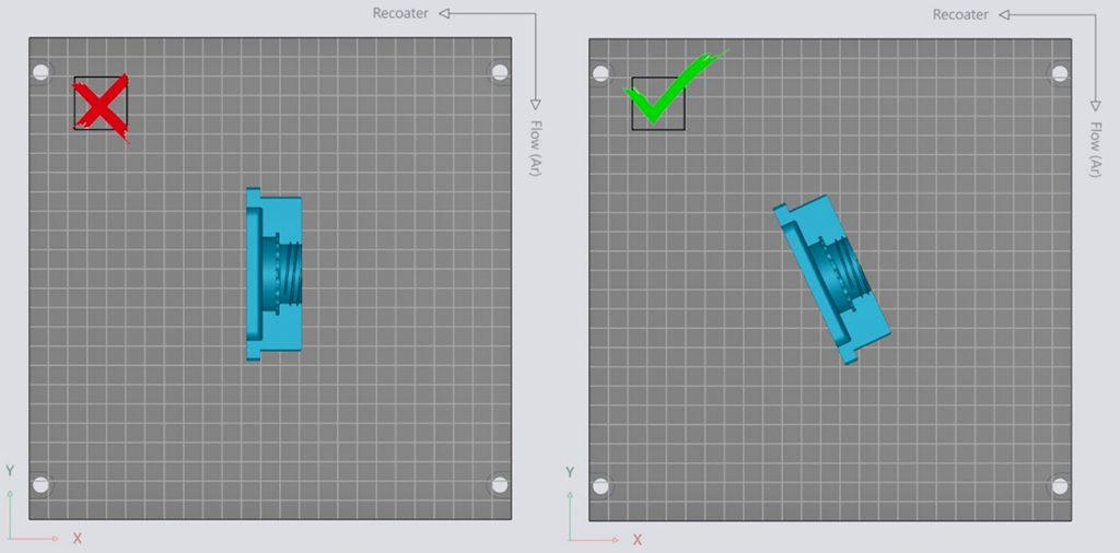
If you position a part parallel to the recoater and any distortion occurs in the part, the recoater may not be able to pass over the distortion and will crash the build. Rotate the part around the Z axis by 5° to 45° so that the recoater does not suddenly meet a long, flat wall. This will greatly reduce the risk of a crash and can improve the quality of delicate features such as thin walls.
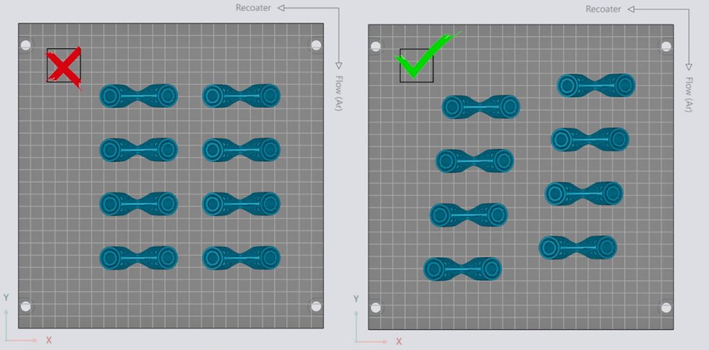
Try to avoid having the recoater make simultaneous contact with several parts at once. Staggering the parts on the build platform is often enough to minimise the risk of large, sudden resistance that can crash the recoater system.
Also avoid positioning parts directly behind one another. If a part distorts and makes contact with the recoater, the build might continue even though the recoater, or the part, is damaged. This is especially the case with silicone or carbon fibre brush blades. If the recoater is damaged, it will affect the quality of the part nested directly in line with the part that damaged the recoater blade.
The effect of this may be a deterioration in the spreading of powder directly behind the collision area. Whenever possible, nest parts on the build plate with space behind them along the recoating axis.
Position the tallest parts closest to the recoater. The reason for this is simple pragmatism. On some AM machines, you cannot place enough powder in the machine to build very tall parts. To build tall parts, the machine may need to be paused while powder is added.

However, some machines may also allow you to reduce the amount of powder deposited in each layer. In this case, one would use a normal amount of powder while the smallest parts are being built. Once these are finished, the amount of powder per layer is reduced to the point where enough powder is available to complete the entire build without needing to pause and refill the machine. Pausing and refilling the build chamber is undesirable due to the possibility of parts shrinking during the cooling time needed to do so.
An understanding of different recoater blade types, and their effects on build quality and reliability, is critical for effective metal AM. Any action that can be taken to minimise any stress on the recoater blade can help ensure parts have the best chance of being successfully additively manufactured.
Authors
Olaf Diegel and Terry Wohlers
Wohlers Associates, Inc.
Fort Collins
Colorado 80525
USA
LAST MONTH’S MOST-READ ARTICLES


