


Distortion in metal Additive Manufacturing: Modelling and mitigation
There is a growing recognition that software can play a vital role in determining the success or failure of Additive Manufacturing within an organisation. As Autodesk’s Michael Gouge and Pan Michaleris explain, metal AM is about far more than having the right machine or specifying the right material. Dedicated AM software can today quickly and accurately simulate distortion in metal AM processes, significantly reducing build failure rates, minimising the associated economic impact and contributing to the enhancement of the technology’s reputation amongst end-users. [First published in Metal AM Vol. 3 No. 1, Spring 2017 | 25 minute read | View on Issuu | Download PDF]
Consider this scenario: a company designs a large titanium part for fabrication in a powder bed AM machine. Months are spent rigorously ensuring that the component will meet the required specifications and geometric tolerances. Days are spent preparing the part to be built. The part is so large it takes up the entire build chamber, so it takes days, if not weeks, to finish manufacturing. Then imagine the part cracks during the final hour of building.
This scenario is not a hypothetical one, but a story related to us by a customer. Every day we talk to companies trying to use Additive Manufacturing to produce usable parts and each of them talks about the same frustrations: excessive distortion, cracking and recoater blade interference.
AM is being sold on the promise that it will make limited production run parts quicker, more efficiently, greener and easier than by using traditional manufacturing methods such as subtractive manufacturing or casting. These promises can only be met after months or years of failed builds produce the expertise within an organisation on how to predict and mitigate build failure before it happens.
Autodesk has acquired a suite of software that packages this expertise together in an intuitive way. The key to avoiding build failure, in particular distortion and recoater blade interference issues, is simulation based mitigation, which is made possible by Netfabb Simulation. This software forms the centrepiece of an integrated design for manufacturability workflow.
This workflow will guide the engineer through the process of designing a part, orienting it on a build plate, optimising the geometry, adding support structures, predicting and preventing build failure and ensuring the built part will meet end-use specifications. In the 20th century a great design engineer would work hand-in-hand with machinists to ensure their vision was feasible. In the 21st century, great design engineers will be marked by their success in designing parts that can be economically and repeatedly manufactured.

The promise of Additive Manufacturing
There is a palpable excitement for Additive Manufacturing, both in the engineering community and the larger world. In the non-technical culture there is a feeling that these machines, transforming a computer generated file into a physical object, are something bordering upon science fiction come to life. For those working in design and manufacturing, these technologies fill very real needs. These needs are: economical small-run production, lowering environmental impacts, improving efficiency and enhancing design capabilities.
AM can create real parts, not just prototypes, in a matter of hours. Wasting less material and, in some cases, expending less energy than subtractive processes, AM can help companies keep their commitments to protecting the environment. With layer-by-layer construction, the popular AM adage ’complexity is free’ does ring true. However, often lauded as a panacea for manufacturing and design challenges, the limitations and complications of what is practicable in AM can come home roughly when the first part, which is almost inevitably badly warped or cracked, is pulled from a company’s first machine. Engineers quickly learn that distortion during a build is the greatest adversity to overcome before the promise of quick, green and complex part manufacture can be realised.
The cost of distortion
Distortion in AM has two costs, one economic, one more intangible. The true monetary cost of a failed part is difficult to calculate as it includes not only the consumption of the raw materials and energy to run the machine, but also the time of technicians and engineers who must redesign and attempt to build the improved part again, the opportunity cost of not manufacturing something else during that period and lead time costs for last minute production runs. The intangible cost is the loss of faith. This can be the lost faith of a customer in a service bureau, or organisational loss of faith in AM as a dependable link in the design and manufacturing chain. Yet distortion during AM is a solvable problem. It requires, however, a deeper understanding of AM processes before the challenge of distortion can be surmounted.

What causes distortion in AM processes?
Distortion is an unavoidable result of heating a small amount of material to its melting point on an otherwise much colder entity [1]. The material in the heat affected zone (HAZ) naturally undergoes thermal expansion, which temporarily bows the part downward while the top layer is still red hot, as the cooler material is forced to bend to accommodate the expansion of the top. As the material cools, there is thermal contraction at the top of the part as the molten material solidifies, which stretches the lower portions of the component so that the it bends upward. The stresses during expansion and contraction are so high that they force the part to yield, which results in permanent deformation.
Distortion is unavoidable, but it can be mitigated. Standard practices to prevent plastic deformation are preheating build plates prior to manufacturing, constantly heating the build plate or build chamber during the manufacturing process, or implementing physical restraints. Preheating and constant heating reduce distortion by decreasing the severity of the thermal gradients which control the extent of the thermal expansion and contraction. While higher temperatures will result in even lower distortion, there are practical limits to what temperatures can be reached [2]. Restraints reduce distortion directly but are limited primarily to reducing build plate distortion in Powder Bed Fusion (PBF) processes. Furthermore, using restraints does not dissipate the bending forces; these forces, instead of causing distortion, result in higher residual stresses. Geometry compensation is the best way forward for improving AM components.
Compensation is a way of changing the part geometry anticipating the distortion that will occur during fabrication, so that the part distorts into the desired final shape. Some of our industrial partners are using experimental scans to compensate geometries. This has two drawbacks: it is expensive to build even a single test part and this method only compensates the external faces of a part. Simulation based compensation will obviate both of these problems, so that a predictive model can guide AM engineers to manufacture better parts with a minimum of failed builds. This will be the central point of development for Autodesk’s AM suite as it strives to ease and automate the design for AM process.
Autodesk’s commitment to Additive Manufacturing
Autodesk is endeavouring to establish itself as an industrial leader in the AM software marketplace. To this end, Autodesk has pursued strategic acquisitions to build a complete additive software portfolio. The ‘grand vision’ is to create a seamless suite of software that encompasses every facet of the design for manufacture process, from CAD to sending the geometry to the AM machine. This will alleviate the many headaches common to piecemeal solutions, including file format conversion, unit errors, inconsistent layout and navigation standards and licensing issues. As the suite becomes fully integrated, with both upstream and downstream compatibility, this will make the iterative design process smoother and quicker, speeding up the time between when the idea for a component is conceived and when a production quality part is pulled from the machine and put to its end use. Currently the core AM suite consists of the following products:

Netfabb
Netfabb began as a small project at FIT Technology Group which then grew into a fully fledged standalone product. Acquired by Autodesk in September 2015, the Netfabb software provides the tools to perform the intermediary steps between component design in a traditional CAD package and manufacturing the part. Netfabb is a platform for path planning, aligning parts on a virtual build-plate, adjusting orientation and automatically adding support structures where needed, in addition to a multiplicity of other pre-build functions such as mesh repair and automated part stamping. Netfabb has become the hub for the other pre-build activities such as part optimisation and build distortion modelling and mitigation.
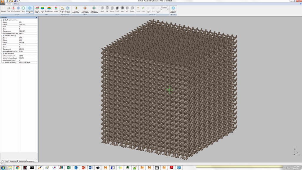
Within
Acquired by Autodesk in May 2014, Within Labs’ software gives design engineers an algorithmic based lattice optimisation tool. Within is used to lightweight components, so only the material required for the specified design performance parameters is used. The lattice optimisation uses Autodesk’s Nastran FEA solver to optimise lattices under user controlled static loading conditions. Within, renamed the Optimization Utility for Netfabb, has been integrated into Netfabb, enabling automated latticing of parts in the optimisation tool, then returning the optimised component to Netfabb for final build preparation.
Delcam
Already an industry leader in Computer Aided Manufacturing (CAM), Delcam’s acquisition in February 2014 by Autodesk expanded the software’s potential market penetration, while providing Autodesk a ready-made suite of both subtractive and Additive Manufacturing digital tools. This CAM software portfolio includes Powermill, Powershape, FeatureCAM and Autodesk HSM. Delcam’s tooling modelling lets designers plan for post-production build plate removal and additional machining. Delcam has recently partnered with Optomec, makers of the LENS® Direct Energy Deposition machines, to provide integrated software for Optomec’s new line of hybrid additive-subtractive manufacturing machines.

Pan Computing
The acquisition of Pan Computing in March of 2016 significantly strengthened Autodesk’s Additive Manufacturing software portfolio. Traditional CAD software, such as Inventor and Fusion 360, enabled component design. Netfabb and Within provided automated tools for pre-production optimisation, support and nesting operations. Pan Computing’s software, formerly known as CUBES and now rebranded as Netfabb Simulation, gives Additive Manufacturing specialists the ability to predict and prevent distortion during the manufacturing process. This shortens the design loop for AM.
Without rapid and accurate simulations, AM parts go through an expensive and laborious iterative manufacturing cycle. Components are built as designed, then measurements are made of distortion and cracking which informs the part redesign. This process continues usually through five to ten build-redesign cycles until the part can be repeatedly built within the specified geometric tolerances. Using the simulation tool, our industrial partners have driven down the number of test builds to two to three before attaining an acceptable built component, saving thousands to tens of thousands of dollars per build. With simulation based compensation it is feasible that parts can be built within tolerance the first time.
Simulation based AM distortion mitigation
Pan Michaleris found himself in a unique position to make a positive impact upon the nascent field of AM modelling. Michaleris is an established expert in welding modelling, having published definitive works in the area and developing distortion mitigation practices that have become standard in industry [3, 4]. Michaleris cut his programming teeth in the early days of the PC, just as the punch card was being phased out. Learning to code with limited computational resources instilled upon him a passion for efficiency. In the beginning of this decade Michaleris turned his attention from welding to AM processes. He found that the processes were similar enough that he could immediately apply his expertise to improve AM modelling. In 2012 he co-founded Pan Computing LLC with the view to producing an accurate and rapid physics based thermomechanical model to predict distortion during Additive Manufacturing processes.
Simulating Direct Energy Deposition, or DED, such as the LENS® process, was the early focus of Pan Computing. Collaborative efforts with Pennsylvania State University, USA, and Sciaky, Inc., Chicago, USA, helped develop and validate the model for laser and electron beam deposition builds. In return, these institutions used knowledge gained from the simulations to implement new techniques to reduce distortion. From these early successes Pan Computing pivoted to the far more daunting task of modelling of Powder Bed Fusion processes. Powder Bed Fusion allows for manufacturing at a much finer resolution, yielding net shape parts that require little to no post processing. PBF has come to dominate the market share of AM space, with its promise of creating beautiful, useful parts in a matter of hours. It was this promise, belied by the experience of company after company, with failed part after failed part, that inspired Pan Computing to develop a tool that was not only accurate, but also fast enough to be useful in industrial practice.
Modelling PBF processes is rife with challenges [5]. These include the addition of material to the model, the application of the heat source, adjusting the boundary losses as the surface evolves, accounting for the temperature dependence of material properties, capturing the stress and strain behaviour during melting, two-phase and solid-state phase transformations, predicting support structure failure and correctly meshing the often complex geometry of PBF components. While the preceding manifold challenges may seem intimidating, this list is missing perhaps the largest difficulty to overcome, the problem of scale when modelling PBF processes with relation to the finite element mesh.
There are two modelling heuristics that drive the computational requirements of a finite element simulation of an additive process. First, to attain accurate thermomechanical predictions of welding, DED, or PBF, the mesh must be sized small enough to capture the melt pool region. Secondly, the discrete time steps taken must be short enough not to induce aliasing. The challenge when moving from DED to PBF modelling hinges upon the fact that the former has melt pools about 1-2 mm across and typically occurring at a rate from 10-25 mm/s, while the latter have melt pools about 0.05-0.2 mm across and melt material at a rate of 500-1000 mm/s. These two requirements make the traditional, direct method of simulation impossible for industrial processes, as they would take hundreds of terrabytes of memory and years to compute.
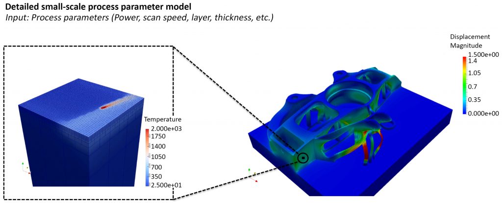
These excessive computational demands have motivated the multi-scale modelling approach. Multi-scale modelling breaks the problem into two. A small scale simulation that models the heat source captures the physics directly. Then a part scale simulation maps results from the small scale simulation to the actual build geometry. This process facilitates the prediction of distortion for large and complex structures in a useful time frame. On a robust workstation an entire simulation, from small scale to part scale can be completed in a few hours for simple parts and within a day for even the largest, most complex parts attempted using the software.
Distortion model validation
The modelling tool was shown to be fast but its accuracy remained to be proven. Through a series of partnerships with public and private entities the simulation tool has been validated for the most popular AM alloys and these efforts are detailed below.
Direct Energy Deposition modelling
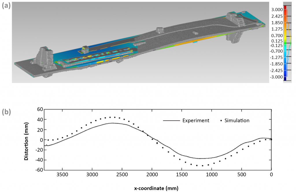
The largest part that we have ever simulated is a test part made by Sciaky, shown in Fig. 8(a) [6]. The base plate was roughly 4.3 m long x 0.5 m wide (14 ft x 18 in.), upon which several kilograms of material was deposited. The deposition was performed using electron beam direct energy deposition. 3D scans were taken of the the finished part, but held back by Sciaky until the simulation results were delivered. The simulations were completed using the direct modelling approach, which took around 24 hours to complete on a 16 core machine. The numerical comparison of the measured distortion is presented in Fig. 8(b), which shows the simulation nearly perfectly captures measured distortion. A subsequent modelling study developed a simple distortion mitigation technique that Sciaky later employed to useful effect [7].
Multi-scale modelling of Laser Powder Bed Fusion processes
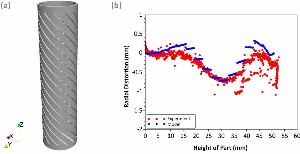
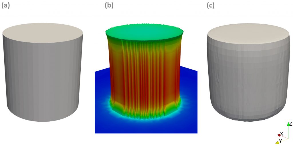
CIMP-3D, The Center for Innovative Materials Processing through Direct Digital Deposition at Penn State was one of the closest collaborators with Pan Computing and continues to be so with the Autodesk Netfabb Simulation team. A recent project headed by Ted Reuxel and Alexander Dunbar involved the modelling of a compliant component they designed, the flexible cylinder shown in Fig. 9(a). The cylinder was built at CIMP-3D on a 3D Systems ProX320 out of Inconel 625, then 3D scanned. A plot of both the measured and modelled distortion along one face of the cylinder is presented in Fig. 9(b). This shows excellent agreement between the model and the built part.
This is but one of numerous validation cases for the modelling of distortion in PBF processes. We have validated the model for Inconel 625, Inconel 718, Inconel 718 Plus, Ti-6Al-4V and AlSi10Mg with builds from GE Global Research Center (GEGRC), United Technologies Research Center (UTRC), Honeywell, Moog and other industrial partners.
While the accurate and rapid prediction of part-scale PBF distortion is the primary use of Netfabb Simulation, there are additional features of the modelling software. These include predicting support structure failure and warning the user if recoater blade interference is likely, along with several other model improvements underway.
Support structure failure and model based support optimisation
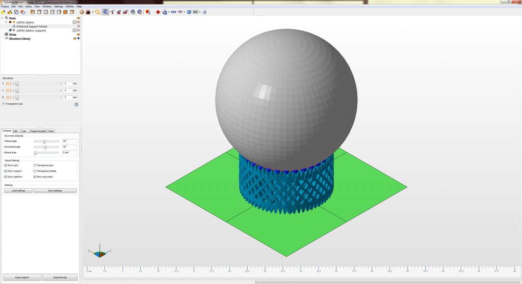
Support structures are the principal tool design engineers and additive technicians have to control distortion in AM processes. The term support structure is somewhat misleading, as the action and purpose of these components is to hold the part down, and not up. This is due to the upwards deflection described previously, so they are employed to anchor parts to the build plate [8]. As this is sacrificial material, supports are generally built much less densely than the component, so these typically are thin walled structures, frequently latticed to further diminish their density and with teeth like connections which ease their removal, as shown in Fig. 10(a). All of these reductions in cross sectional area increase stresses applied to supports during manufacture. These stresses can often exceed the support structure’s tensile strength, resulting in failure. This can lead to the excessive distortion the supports that were put in place to prevent, and in the worst cases lead to, recoater blade interference. This issue is described more in detail later.
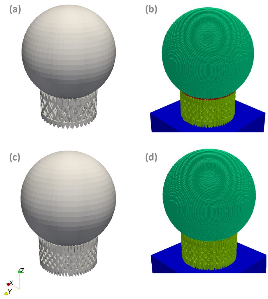
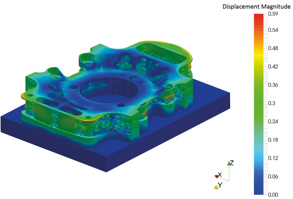
Netfabb Simulation has implemented support structure failure prediction to help improve the reliability of PBF builds. Support structures may be modelled directly or homogenised to coarsen the elements to speed up simulation times. Support failure is indicated visually in the results, as shown in Fig. 10(b). Inspection of the failure region and geometry lets AM engineers thicken up the anchoring structures just in the region of concern, as illustrated in Fig. 10(c). The strengthened supports experience a significant reduction in failure, as shown in Fig. 10(d). Using simulation based optimised supports will produce a better physical part once built. Alternatively, overly bulky structures may be iteratively reduced to minimise material costs via the same methodology. Using the modelling software support structure failure prediction prior to attempting building can be used to reduce excessive distortion or material wastage, improving the economic feasibility of AM practice.
Recoater blade interference
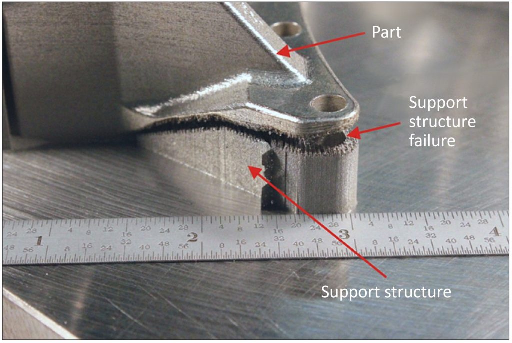
Recoater blade interference is the most destructive and expensive form of failure in PBF processes. This occurs when the upward distortion is so excessive that the top of the build component juts above height of the top of the next powder layer. When the powder is being spread back over the build chamber, the powder spreading device, called the recoater, will collide with the component. Some machine manufacturers have designed their recoating device to be out of a compliant material, such as a polymer or elastomer. These will experience minimal to no damage upon contact with the component, but the integrity of the build geometry will be reduced as there will be a portion of the build surface with one or more incomplete powder layers. Many manufacturers still use metal recoater blades and when these impact the component the failure can be catastrophic. The recoater will likely damage the part and in turn the part will bend and warp the recoater blade. This means the machine will have to be repaired, the recoater replaced and the component rebuilt from the beginning.
Recoater blade interference is predicted by Netfabb Simulation as an extension of its distortion modelling. During the part level build simulation the code checks if the vertical displacement is large enough to warrant concern about recoater collisions. The user will be issued a warning if the upwards distortion is extreme enough to cause an recoater collision incident. This method has been experimentally validated due to the misfortune of one of our customers, evidenced in Fig. 11.
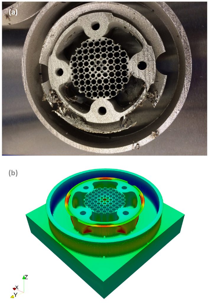
Modelling was performed a posteriori of a part that was known to experience recoater blade interference. Fig. 11(a) clearly shows the damage caused by the recoater-part collision. The model predicts excessive vertical deflection at the same height and planar location, as shown in Fig. 11(b). This validates the ability of the model to warn users about potential recoater issues. This predictive tool enables engineers to redesign, reorient and add support structure components to eliminate the threat of recoater blade interference.
Simulation based geometry compensation
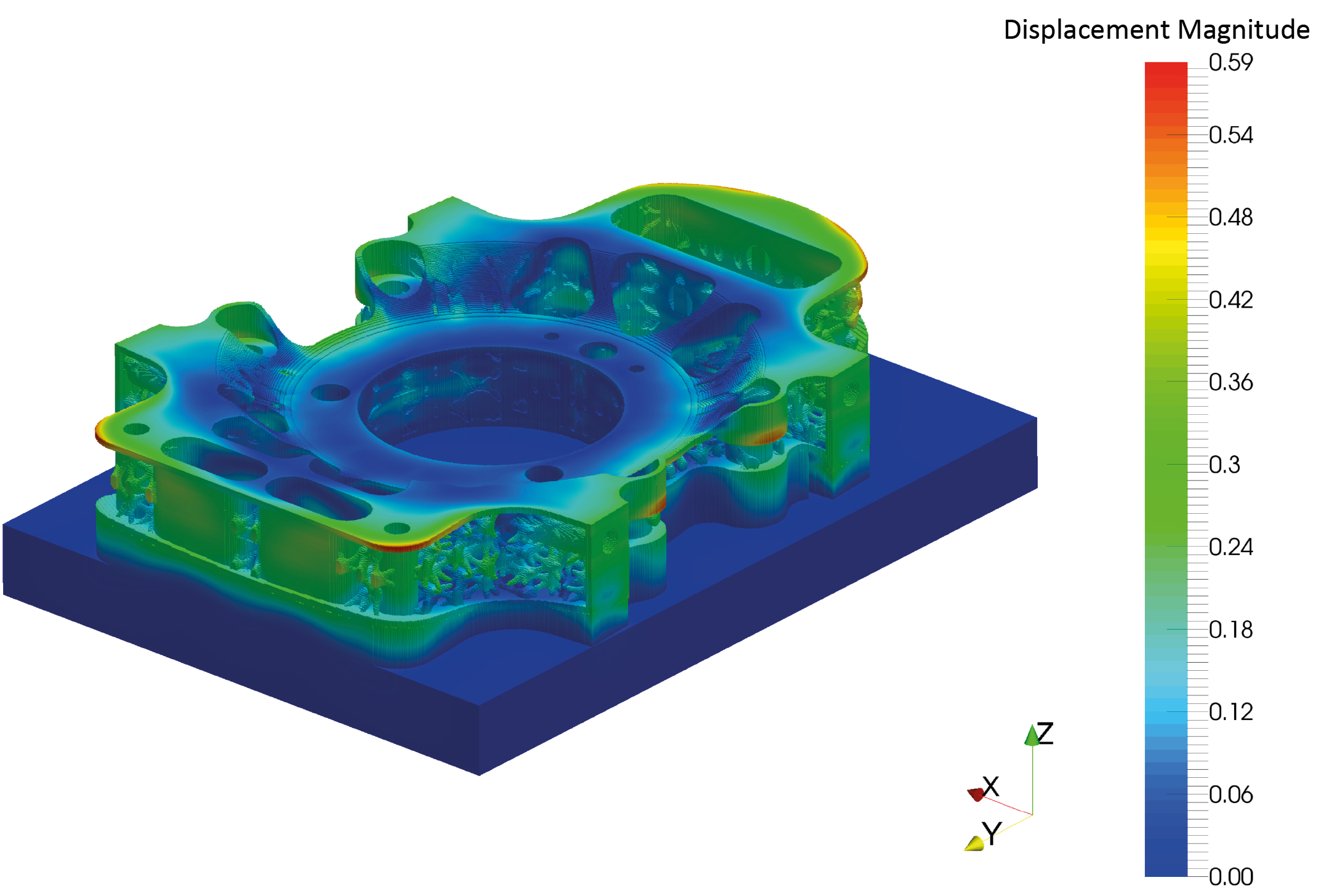
Producing a geometry that can be manufactured free of distortion the first time around is the ultimate goal for any AM simulation software. Current users in industry report that using the simulation tool they are able to bring the number of builds before obtaining a usable component from five to ten to perhaps two or three. Geometric compensation, where a part is altered based upon the measured or simulated distortion so it warps into place, as depicted in Fig. 12, has been hypothesised as the silver bullet for eliminating unwanted distortion. This would drive the builds required to produce a usable part from a new geometry down to one and would be a threshold achievement for the AM industry.
Simulation-based compensation would eliminate one of the biggest recurring costs to designing a part for metal AM construction, the thousands or tens of thousands of dollars spent perfecting the geometry through trial and error. With a compensation tool, parts that would have been economically unsound to manufacture become feasible. Businesses would recoup their AM investments in a much shorter time frame and industrial adoption would accelerate. This, in turn, would trigger economies of scale, which will bring AM out of its current niche research and development state to become as standard and unremarkable a part of a manufacturing chain as the end-mill.
Netfabb Simulation has a model based compensation tool currently in testing. Compensated geometries have been manufactured from simulation results by several of our industrial partners as part of both ongoing research and for real world applications.
Future outlook
Both Additive Manufacturing and the simulation of additive processes are in their nascency. Practices and technology are still in development and in flux and each year machine manufacturers are able to produce parts with finer resolution and in shorter times. Netfabb Simulation, though in a class by itself as a truly predictive software for AM distortion prediction, failure mitigation and optimisation, has plenty of room to improve and expand its capabilities. In the near term this includes the addition of validated materials, prediction of stresses and cracking and post-build heat treatment.
Expanded material support
Currently Netfabb Simulation has been validated for Inconel 625, Inconel 718, Inconel 718 Plus, Ti-6Al-4V, CoCr and AlSi10Mg. Autodesk has agreements with multiple organisations to build validation test plates for the addition of cobalt chrome, 316L, 17-4 PH and 15-5 PH stainless steels and AISI 4340 low alloy steel modelling capabilities. This plan will be executed in the first half of 2017.
Crack prediction
Some common AM materials, particularly titanium alloys, are quite susceptible to cracking during PBF. This is a current focus of the Netfabb Simulation research team. Efforts are being made to apply traditional fracture mechanics methods, with crack initiation and crack propagation models, to the build process simulation. Crack modelling may require refinements in stress prediction methods and addition of measurements of material toughness to the list of material properties needed to complete the simulation.
Heat treatment modelling
Common heat treating processes for additive parts are stress relaxation, annealing, quenching, and Hot Isostatic Pressing (HIP). These are used to remove residual stresses, homogenise and refine the microstructure and reduce porosity. These thermal processes may cause additional distortion or even cracking in the part. Modelling post processing will allow AM engineers to predict and mitigate undesirable behaviour using these techniques while also giving practitioners guidance for implementing them.
Further integration of Autodesk AM software tools
The Netfabb bundle is CAD agnostic, with over 40 supported file types users can create their geometry in almost any CAD tool and use it within the preparation-optimisation-distortion prediction suite. Yet it would further ease the wall-less design if Autodesk’s engineering oriented CAD packages, Inventor and Fusion 360, could export parts designed for powder bed construction directly to the Netfabb bundle.
At the other end of the design process, it would be similarly advantageous to be able to feed the simulated, warped geometry into Nastran, Autodesk’s general purpose FE package. Then the user could ensure that not only would the as built part meet its geometric requirements, it could also be tested to ensure it upholds its design though analysis of its performance with regards to heat transfer, failure, fatigue, etc.
Finally, work has already begun integrating both Netfabb Optimization and Netfabb Simulation with Dreamcatcher. Dreamcatcher is a general purpose optimisation software that can provide detailed analysis, machine based design and material suggestions. Using this optimisation software could further guide or even automate component design for additively manufactured parts.
Conclusions
Excessive distortion during the build process is the largest impediment for AM technologies to become economically feasible and widely implemented in everyday manufacturing practice. Netfabb Simulation offers the predictive capabilities to reduce distortion, along with the related phenomena, support structure failure and recoater blade interference. This simulation tool has been thoroughly validated for both DED and PBF processes. Modelling can then guide distortion mitigation efforts to reduce the number of build failures for a new geometry.
Using simulation based compensated geometries automates the design for manufacturability process, further reducing, or altogether eliminating distortion driven build failures. The near term future improvements, validating additional materials, implementing crack prediction and extending the model to heat treatment processes, will result in an even more robust predictive tool that will reduce wastage and accelerate the adoption of AM at the industrial scale.
Author
Michael Gouge and Pan Michaleris
Autodesk Inc.
200 Innovation BLVD
Suite 208
State College, PA 16803
USA
Tel:: +1 814 954 7109
Email: [email protected], [email protected]
www.netfabb.com/capabilities/simulation
References
[1] Erik R Denlinger, Jarred C Heigel, Pan Michaleris and TA Palmer. Effect of inter-layer dwell time on distortion and residual stress in Additive Manufacturing of titanium and nickel alloys Journal of Materials Processing Technology, 215:123–131, 2015.
[2] M Shiomi, K Osakada, K Nakamura, T Yamashita, and F Abe. Residual stress within metallic model made by selective laser melting process. CIRP Annals-Manufacturing Technology, 53(1):195–198, 2004.
[3] Panagiotis Michaleris and Andrew DeBiccari. Prediction of welding distortion. Welding Journal-Including Welding Research Supplement, 76(4):172s, 1997.
[4] P Michaleris, J Dantzig, and D Tortorelli. Minimization of welding residual stress and distortion in large structures. Welding Journal-New York-, 78:361–s, 1999.
[5] Panagiotis Michaleris. Modelling metal deposition in heat transfer analyses of additive manufacturing processes. Finite Elements in Analysis and Design, 86:51–60, 2014.
[6] Erik R Denlinger, Jeff Irwin, and Pan Michaleris. Thermomechanical Modelling of additive manufacturing large parts. Journal of Manufacturing Science and Engineering, 136(6):061007, 2014.
[7] Erik R Denlinger and Pan Michaleris. Mitigation of distortion in large additive manufacturing parts. Proceedings of the Institution of Mechanical Engineers, Part B: Journal of Engineering Manufacture, page 0954405415578580, 2015.
[8] Wei Gao, Yunbo Zhang, Devarajan Ramanujan, Karthik Ramani, Yong Chen, Christopher B Williams, Charlie CL Wang, Yung C Shin, Song Zhang, and Pablo D Zavattieri. The status, challenges, and future of additive manufacturing in engineering. Computer-Aided Design, 69:65–89, 2015.
LAST MONTH’S MOST-READ ARTICLES


