Combining Metal AM and Hot Isostatic Pressing (HIP): Application and process innovations
A technical session at the Euro PM2017 conference, held in Milan, Italy, October 1-5, 2017, investigated three different concepts in processes that combine metal Additive Manufacturing with Hot Isostatic Pressing (HIP). In the following report, Dr David Whittaker reviews three papers that consider the use of SLM for the manufacture of HIP capsules, HIP as a final densification process in AM, and finally HIP as a process to join EBM processed components into larger structures. [First published in Metal AM Vol. 3 No. 4, Winter 2017 | 20 minute read | View on Issuu | Download PDF]
Selective Laser Melting for thin-walled HIP capsule manufacture
A paper from Sebastian Riehm, Anke Kaletsch and Christoph Broeckmann (RWTH Aachen, Germany) and Sandra Wieland and Frank Petzoldt (Fraunhofer IFAM, Bremen, Germany) investigated the use of Selective Laser Melting (SLM) for HIP capsule manufacture, as an alternative to the expensive and time-consuming approach of fabrication from sheet metal. The investigated approach was to build open capsules by SLM and fill them conventionally with powder for HIPing.

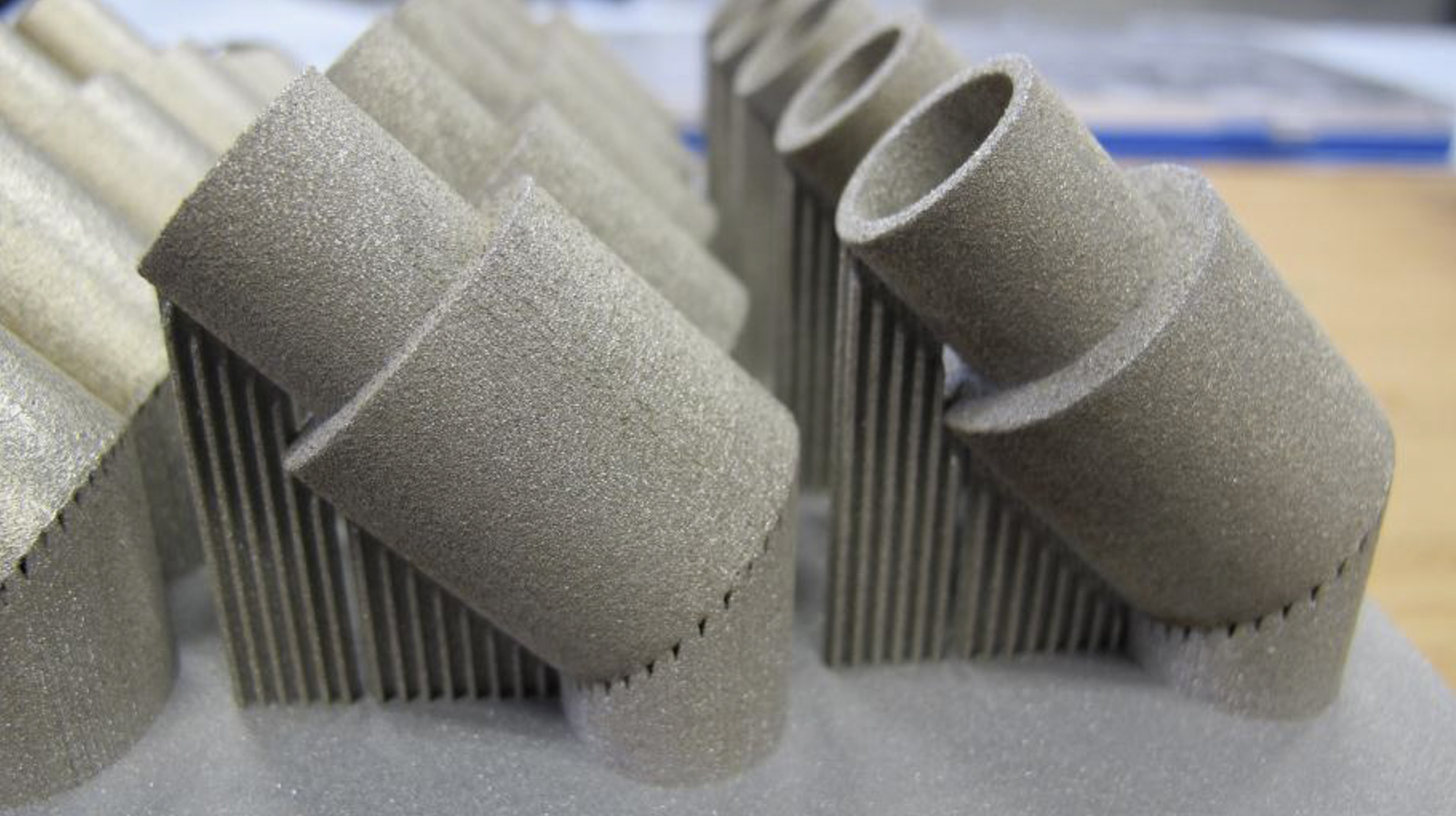
In the reported study, the production of monolithic components through this combination of SLM and HIP was presented. As a further variant of this route, the outer capsule could be made from a wear- or corrosion-resistant material, with the inner bulk material offering high toughness and strength. For this approach, the capsule was manufactured as an open hollow body. Building components by SLM is a time-consuming process and, therefore, the thickness of the capsules was kept to an absolute minimum. After SLM-building, a filling pipe was conventionally welded onto the capsule, allowing filling and closing of the capsule. This combined process allows the production of complex net-shape composite components.
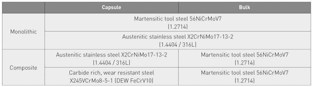
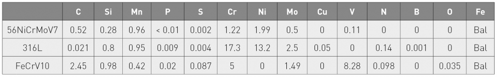
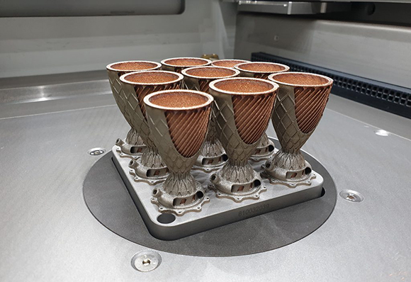
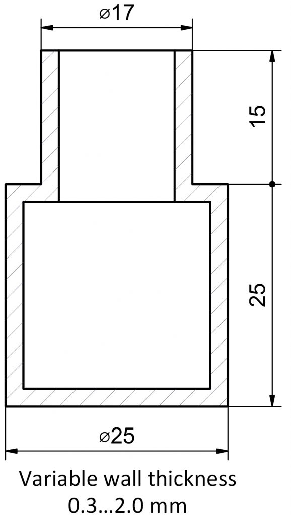
Table 1 shows four combinations of materials: two monolithics, where capsule and bulk were from the same material, and two composites, where a capsule of stainless or wear resistant steel was to be filled with powder of tool steel. The chemical compositions of the investigated powders can be seen in Table 2. While the goal of this project was to build complex composite components by SLM and HIP, some initial basic experiments were conducted with simple cylindrical capsules. Fig. 2 shows the geometry and the first batch of SLM-manufactured cylinders with outer diameter of 25 mm and height of 25 mm. The wall thickness of the cylinders varied from 0.3 mm to 2.0 mm. The cylinders were produced at IFAM using an EOS M270 Dual Mode SLM machine.
After the SLM build, the cylinders were removed from the building platform and the support structure was removed from the cylinders by wire erosion. Afterwards, a longer filling pipe was TIG welded onto the short SLM-made lug. Every capsule was filled with 316L powder to a relative density of around 50 to 60%, evacuated and sealed.
Capsules with a wall thickness of less than 1 mm had defects, in that they either had holes from the wire erosion or the welding of the pipes was not successful. For this reason, only three capsules with wall thicknesses of 1.0 mm, 1.5 mm and 2.0 mm could be prepared for the first HIP cycle.
The deformation and shrinkage during HIP can be numerically simulated by FEM-based methods. In order to design a net-shape component, the necessary geometry of the capsule prior to HIP can be optimised by using this numerical simulation routine.

In this study, a macroscopic simulation model was used, based on a yield criterion and particularly formulated for porous continua. The simulation routine was implemented as a user sub-routine in the commercial FEM software package Simulia Abaqus.
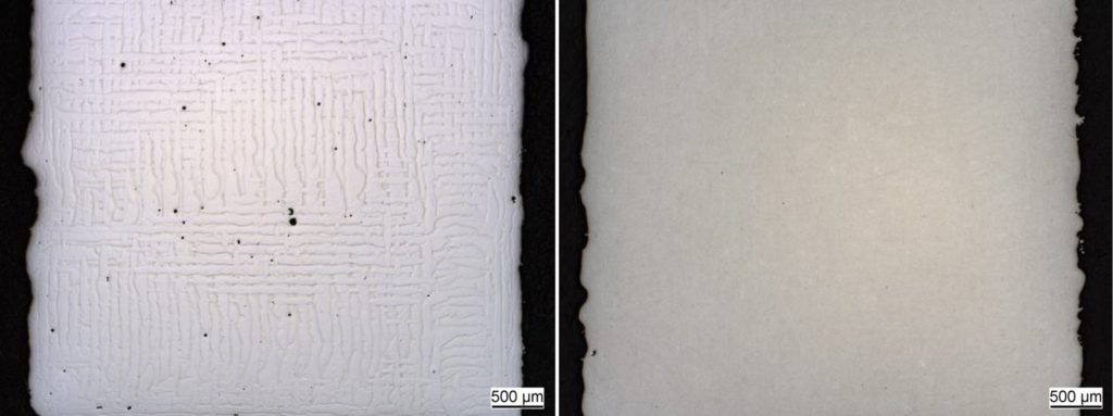
Prior to the first HIP cycle with SLM-built capsules, an experimental cycle was conducted to investigate the influence of HIP on the microstructure of carbide rich steel samples made by SLM. Samples of around 5 x 5 x 5 mm were built from a powder mixture of 82.5 w% FeCrV10 + 17.5 w% X6Cr17. The HIP parameters used were: Temperature = 1100°C, Pressure = 100 MPa, Holding time at temperature = 120 min.
Fig. 3 shows micrographs of the SLM samples of the FeCrV10 mixture: (left) before HIP and (right) after HIP. In the as-built state, the melting traces of the laser beam were clearly visible and pores and voids could be seen. In the as-HIPped state, nearly all voids had been closed and the material was homogenised; the laser beam tracks were no longer visible.
The SLM-made capsules were subsequently filled with powder, evacuated, gas-tightly closed and hot isostatically pressed using the following HIP parameters: Temperature = 1125°C, Pressure = 110 MPa, Holding time at temperature = 120 min. The capsules with a wall thickness of 1.5 mm and 2.0 mm were densified. Only the capsule, with wall thickness of 1.0 mm, did not densify, because it was not gas-tight.
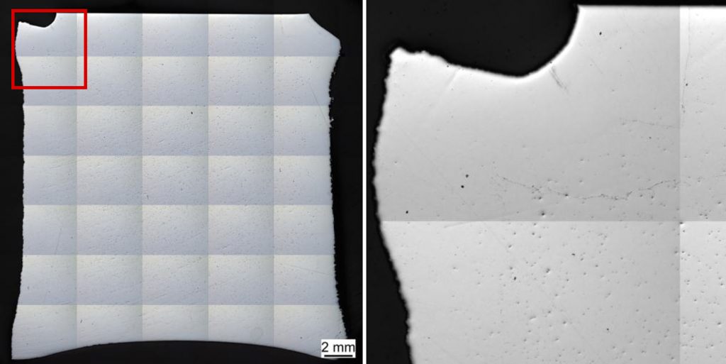
Fig. 4 (left) shows a cross section of the capsule with 1.5 mm wall thickness. The densification and high homogeneity are obvious. In Fig. 4 (right), a detailed view of the upper left corner is shown. While there are only very few pores and voids in the capsule, the inner bulk exhibits a high number of irregularities. This is now the subject of further investigations to determine which of these voids are real pores and which are merely artefacts of metallographic preparation. The interface region between capsule and bulk powder can still be easily identified.
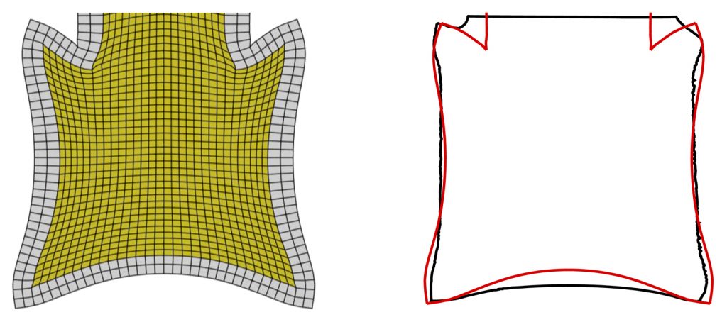
In this early state of the project, the geometry of the capsules has not been optimised by numerical FEM simulation. Instead, the initial geometry of the capsules was numerically modelled in order to compare the calculated and the real dimensions after HIP. In a further step, capsule geometry will be optimised to obtain the desired shape after HIP. The results of the current FEM simulation are shown in Fig. 5 and indicate full densification of the entire sample. Fig. 5 also shows the results of the simulated contour of the capsule after HIP (red solid line) and the experimentally determined contour after HIP (black solid line). The model is clearly already well capable of predicting qualitatively the shrinkage during HIP, but, in terms of quantitative accuracy, there is potential for improvement. Particularly at the bottom, the simulation routine seems to overestimate the shrinkage. It was noted that simulation results of conventionally produced capsules, made by the welding of sheet metal, yield a much better quantitative accuracy.
As SLM components are built layer by layer, they exhibit anisotropic material parameters. Therefore, properties depend on the building direction. It remains to be investigated the extent to which material properties of conventional material can be used for additively manufactured material.
Two other mechanisms that could have an impact on the component after HIP are friction and gravity: The base components of the HIP unit cause a counterforce to the shrinkage of the body. This counterforce impedes the shrinkage. Also, gravity acting on the powder particles influences the deformation. These results are strong evidence that gravity and friction need to be taken into consideration in HIP simulation.
HIP as post-build densification treatment in Additive Manufacturing
A paper, from Johannes Kunz, Anke Kaletsch and Christoph Broeckmann (RWTH Aachen University, Germany), then focused on the more “standard” combination of the two technologies, with HIP being used as a post-build densification treatment. The reported study was aimed at assessing the influences of both the HIP treatment and build position on the SLM platform on the derived mechanical properties.
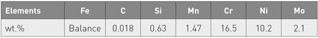
In the study, the powder used was a type 316L stainless steel with a material density of 7.91 g/c m3 and a chemical composition as shown in Table 3. This powder was manufactured by gas atomisation by Carpenter Powder Products Inc. The powder particles had spherical or nearly spherical shapes with some satellite particles. The powder size distribution was determined and exhibited d10 = 30.9 µm , d50 = 42.2 µm and d90 = 60.2 µm, thus showing a shifted and closer particle distribution than that commonly used in SLM powders. A bulk density of 4.15 g/ cm³ was determined. In an earlier study by the same authors, the fatigue strength was determined by rotating bend fatigue testing. The staircase procedure with a surviving level of 107 cycles was applied. The fatigue strengths were determined for a fracture probability of 50%. The fatigue strengths, σA,50, were around 305 MPa in the as-built condition and around 338 MPa after HIP.

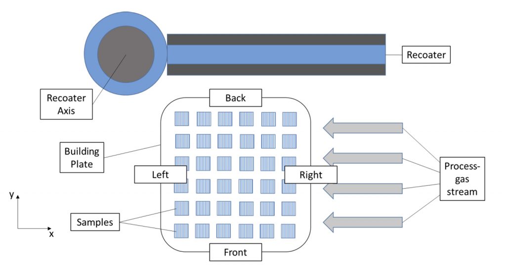
In this further study, SLM was carried out using a SLM 100 machine (Realizer GmbH), working with a Ytterbium 200 W fibre laser and a layer thickness of 50 µm. Scanning parameters, such as laser power, laser focus, scanning speed and hatch strategy, were defined for the support structure, outer boundaries and inner areas. These parameters were optimised with respect to density. The density-optimised set of parameters led to a sample density of 7.91 g/cm³. During the process, argon was used as the process gas. Fig. 6 shows the schematic setup of the building chamber in the SLM process.
For the mechanical test programme, highly filled building plates were produced, with 36 cylinders or 25 cuboid samples produced on each building plate. The post-build HIP cycle was carried out at a temperature of 1125°C, a pressure of 100 MPa and a dwell time of 3 h.
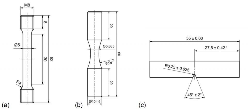
Tensile tests, rotating bend fatigue tests and Charpy impact tests were performed. As the focus of this study was on the influence of building position and HIP post treatment on the bulk material properties, the original SLM specimen surfaces were removed by machining. The cylinders manufactured by SLM were machined to the sample geometry, shown in Fig. 7 (a).
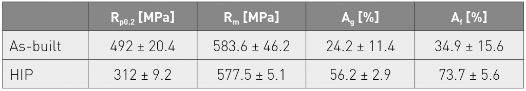
In the SLM condition, the average tensile strength of all samples was determined as 583.6 ± 46.2 MPa and the average uniform elongation as 24.2 ± 11.4%. Fig. 8 shows the tensile strength and uniform elongation as a function of the position on the plate. The lines represent samples at the back, middle and front from left (position 1) to right (position 3) on the plate. In the middle and back positions, only small variations are visible. The front line positions 2 and 3 show the lowest values of elongation. The tensile strength drops significantly in position 3. This position is characterised by having the largest distance from the rotation axis of the recoater.
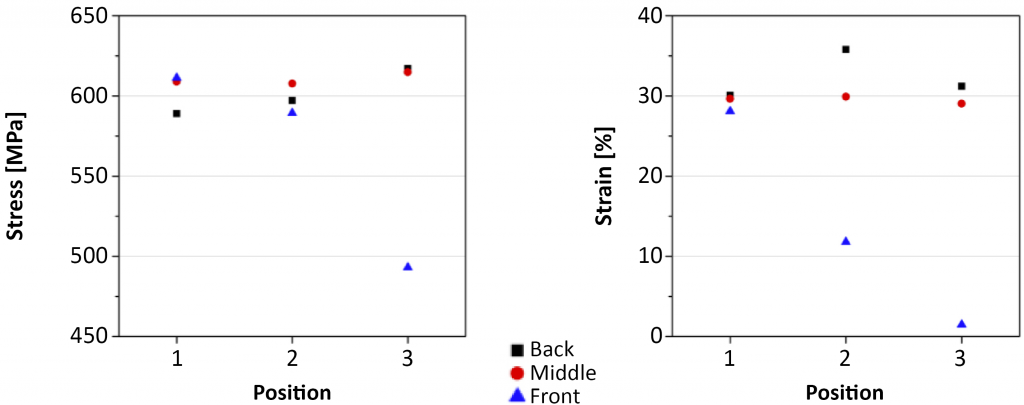
Table 4 shows proof stress Rp0.2, ultimate tensile strength Rm, uniform elongation Ag and fracture elongation Af of the samples in the as-built and HIPed conditions. After HIP, a tensile strength of 577.5 ± 5.1 MPa, a uniform elongation of 56.2 ± 2.9% and a fracture elongation of 73.7 ± 5.6% were measured. It was therefore evident that the large scatter in properties could be reduced by HIP.
For the determination of the fatigue properties, rotating bending tests were carried out with a stress ratio of R = -1. The cylindrical samples were machined to the sample geometry as shown in Fig. 7 (b). The tests were performed with a frequency of about 100 Hz. The stress amplitude was set at 310 MPa for the as-built condition and 340 MPa for the HIPed condition. These values were slightly above the fatigue strengths determined in the prior study. The survival level was set at 107 cycles. Surviving samples were tested again at a higher stress level. The fracture origins were identified by Scanning Electron Microscopy (SEM) analysis.

In the fatigue testing, only one sample in the as-built condition fulfilled the survival level of 107 cycles.
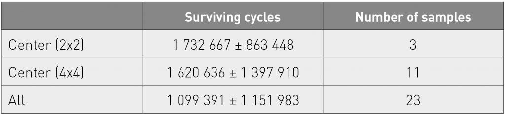
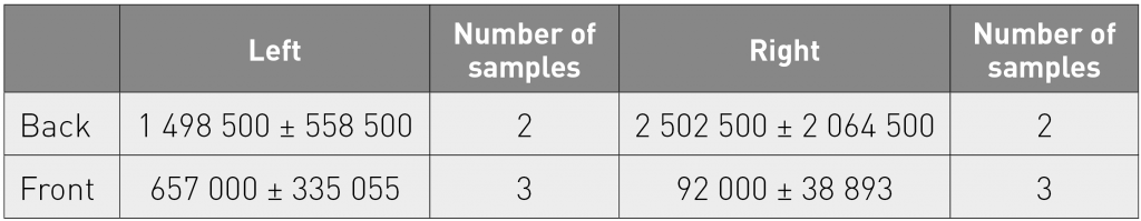
Table 5 and Table 6 show the average surviving cycles of premature failures in different areas of the building plate. The values were taken from the centre 2 x 2, the centre 4 x 4 area and the 2 x 2 corners. Additionally, an average over the entire building plate is given, excluding those locations that were used in the tensile tests. Closer to the outer area, the average surviving cycle number is reduced. The front right corner exhibits a tendency to low cycle numbers.
After HIP, at a stress level of 340 MPa, five samples broke before fulfilling the survival level demand. The broken samples had an average cycle number of 1,788,600 ± 936,242. At a stress level of 380 MPa, five samples reached the survival level demand. The average cycle numbers of the failures are 143,000 ± 101,008. After HIP, no obvious dependency between the number of cycles survived and the building position could be observed.
Fracture analysis, using SEM and EDX, on premature failures has attributed the fracture origin to two main defects, pores and oxidation phases. EDX analysis on the oxides showed the constituents to be mainly silicon, chromium, manganese and oxygen.
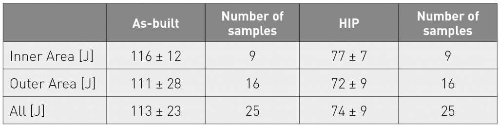
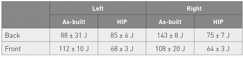
Charpy impact tests were conducted, with the cuboid samples being machined to the specimen geometry shown in Fig. 7 (c). The as-built samples exhibited an impact toughness at room temperature of 113 ± 23 J. After HIP post-treatment, an average toughness of 74 ± 9 J was measured. An overview of the toughness in the as-built and HIPped states is given in Table 7. By subdividing the plate into inner (3 x 3) and outer area, a tendency can be seen. A toughness of 116 ± 12 J for the inner area and of 111 ± 28 J for the outer area was measured. Table 8 shows the values of the areas (2 x 2 samples) located at the corners in the as-built and HIPed conditions. The area located back left exhibits the lowest impact toughness with the largest standard deviation. The difference between the areas with the highest and lowest values is about 55 J. After HIP, the largest difference in toughness is about 25 J and can be found along the plate diagonal (back left to front right).
The authors drew the following overall conclusions:
- Tensile tests, Charpy impact tests and rotating bend fatigue tests revealed a positional dependence for samples in the as-built condition. In all tests, a regional variation could be observed. In particular, the ductility and the fatigue strength were highly sensitive to the building position.
- Post-build HIP treatment decreased the deviation of properties on a building plate.
- Due to the reduced porosity level, the fatigue strength increased after HIP
- A post-build HIP treatment also increased ductility
- Average toughness decreased after post-build HIP treatment, but the variability was reduced
This study has, therefore, indicated that a HIP post-treatment improves the reproducibility of properties of SLM samples.
For future investigations, the authors plan to examine the influence of HIP treatment followed by solution annealing with rapid cooling on the toughness.
HIP bonding of EBM-built blocks
Finally, Pelle Mellin, Hans Magnusson and Joakim Algardh (Swerea KIMAB, Sweden), Peter Harlin (Sandvik Materials Technology, Sweden), Stefan Wikman (F4E, Spain), Jon Olsen and James Shen (Stockholm University, Sweden), Lars-Erik Rannar (Mid Sweden University) and Lars Nyborg (Chalmers University of Technology, Sweden) reported on a study of a process route involving the HIP-bonding of EBM-built blocks of 316L stainless steel, with particular reference to a potential application in an experimental nuclear fusion reactor.
316L stainless steel is the designated material for use in the First Wall Beam in the ITER reactor. In contrast to previous research on HIP-bonding of 316L, the material in this paper was built by EBM. HIP of EBM highly critical components, to heal any defects, such as pores and cracks, is usually advisable, in any case. Using HIP to simultaneously bond several print jobs together into a larger component saves time and reduces manufacturing complexity.
Two attempts to bond blocks were made. In a preliminary test, the surface roughness of the blocks was varied. Secondly, a test using larger blocks was carried out, using the most successful surface preparations from the preliminary test and, in this case, HIP parameters were instead varied.
The preliminary test involved the use of the ‘raw’ as-built surface finish and the use of milling and electro-discharge machining (EDM) to refine surface finish.
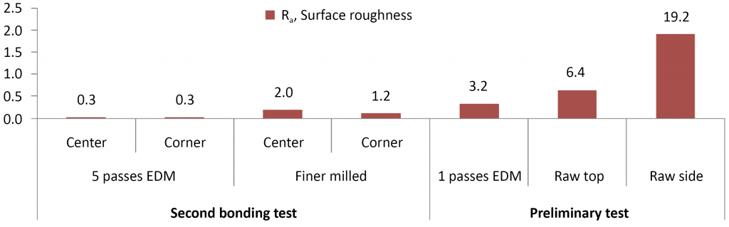
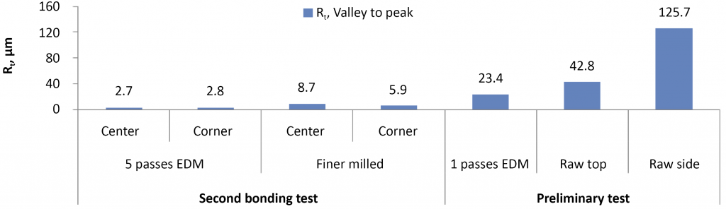
The various surface finishes are characterised in terms of Ra and Rt (peak to valley distance) in Figs. 9 and 10, respectively.
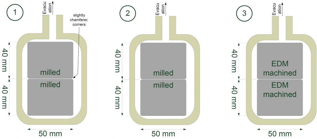
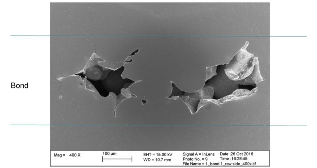
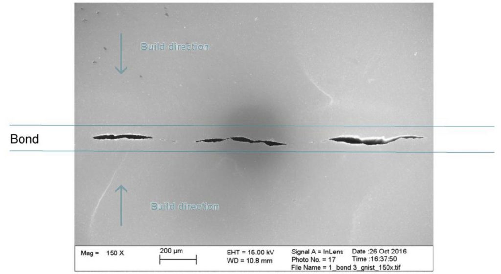
In this preliminary test, slices with the prepared surfaces were put into a HIP capsule as a stack of slices. Fig. 11 shows the iron capsules that were used to enclose the blocks to be bonded. Evacuation, in order to not trap any gases in the bond, was performed before welding the capsules and pressing them. The HIP cycle applied (by Sandvik Materials Technology) comprised 1150°C HIP temperature, 1000 bar pressure and 1 hour holding time.
SEM was used to investigate the centre of the bonds, with the outcome shown in Figs. 12 and 13. Here, none of the surfaces were completely bonded, although the milled surfaces were much closer to a complete bond.
In the second set of tests, larger blocks were used and milling was selected as the preferred surface finish modification method. HIP parameters were varied, according to the following programs:
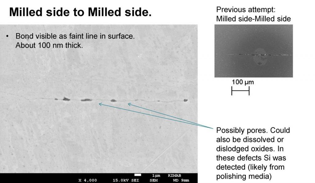
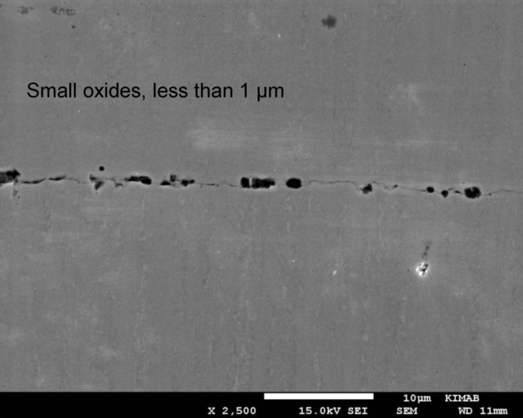
- 1150°C, 1000 bar, holding time 2 h (carried out by Swerea KIMAB). This cycle ran 1 capsule for the second test, containing milled blocks and produced a near perfect bond (Fig. 15)
- 1200°C, 1000 bar, holding time 2 h (carried out by Swerea KIMAB). This cycle ran 1 capsule for the second test, containing milled blocks and, again, produced a near perfect bond. Also, 1 capsule for the second test, containing EDM-cut blocks, was run. Incomplete bonding resulted, in this case (Fig. 15).
The conclusion drawn from the preliminary test was that fine surface roughness is an important enabler for a good bond. High HIP temperature, pressure or time could also offset a rougher surface, although more severe HIP conditions can also increase the risk of shape distortion and abnormal grain growth. During the second set of tests, it was demonstrated that finer surfaces (Ra = 2 µm) and longer HIP time (2 h) (without increasing HIP temperature) could be used to achieve a good bond.
References
[1] Net-Shape Components Produced By Combining Additive Manufacturing And Hot-Isostatic Pressing, S Riehm, A Kaletsch, C Broeckmann, S Wieland and F Petzold, as presented at Euro PM2017 Congress and Exhibition, Milan, Italy, October 1-5, 2017, and published in the Conference Proceedings by the European Powder Metallurgy Association (EPMA).
[2] Influence of the Building Position and Post HIP Treatment on Properties of SLM Components, J Kunz, A Kaletsch and C Broeckmann, as presented at Euro PM2017 Congress and Exhibition, Milan, Italy, October 1-5, 2017, and published in the Conference Proceedings by the European Powder Metallurgy Association (EPMA).
[3] Bonding EBM-built Blocks of 316L Steel, Using Hot Isostatic Pressing, P Mellin, H Magnusson, P Harlin, S Wikman, J Olsén, Z J Shen, L-E Rännar, J Ålgårdh and L Nyborg, as presented at Euro PM2017 Congress and Exhibition, Milan, Italy, October 1-5, 2017, and published in the Conference Proceedings by the European Powder Metallurgy Association (EPMA).
Author
Dr David Whittaker
Tel: +44 1902 338498
Email: [email protected]
Euro PM2017 Proceedings
The full proceedings of the Euro PM2017 Congress is now available to purchase from the European Powder Metallurgy Association. Published as a USB drive, topics covered include:
- Additive Manufacturing
- PM Structural Parts
- Hard Materials & Diamond Tools
- Hot Isostatic Pressing
- New Materials & Applications
- Powder Injection Moulding
LAST MONTH’S MOST-READ ARTICLES