


Planning, preparing and producing: Walking the tightrope between additive and subtractive manufacturing
In the following article Delcam’s Kelvin Hamilton explores the current possibilities for design, topology optimisation, simulation, process planning and process preparation in metal Additive Manufacturing. Exploring the three Ps, Plan, Prepare and Produce, all the processes involved in transforming three airbrake bracket designs into final products are revealed. As well as explaining how important it is to appreciate and plan for the significant amount of subtractive manufacturing in metal AM, a number of the lessons learnt in this project are discussed as the author reflects on the experience of planning, preparing and producing parts. [First published in Metal AM Vol. 2 No. 1, Spring 2016 | 40 minute read | View on Issuu | Download PDF]
If you ask anyone involved with metal Additive Manufacturing, they will tell you that producing quality parts always requires some kind of post-processing operation. AM should therefore be understood as one of the many processes that can be utilised to manufacture a part, not an end-to-end solution that stands alone. At Delcam, we have been involved with the production of metal AM parts for some time. Yet, time and again, we see the same mistakes preventing manufacturers from achieving the part geometry that they are trying to create.
Our experience tells us that the key to successfully producing quality metal AM parts lies in creating a comprehensive process plan [1]. This requires expertise not only in Additive Manufacturing, but in every process required to manufacture the finished parts. Understanding how to account for subtractive implications on the additive process at both the design and build preparation stages must be built into the process plan. For the parts discussed here, we started by looking at the role of software within the process chain. More specifically, we looked at the tools available within Delcam and Autodesk to see how we can best incorporate this exciting process in anticipation of what the World Economic Forum calls the fourth industrial revolution [2].

Objectives
In order to understand the possibilities and limitations of the wide range of tools available to us, we took a known geometry from design all the way through to manufacture and post-processing. The aim was to explore whether the design and manufacturing software and processes available today could be used coherently to enable the additive and subtractive manufacture of quality metal parts.
At worst, we would identify roadblocks that prevent coherent workflows and explore how we could facilitate seamless workflows between design, preparation and post-processing.
The part
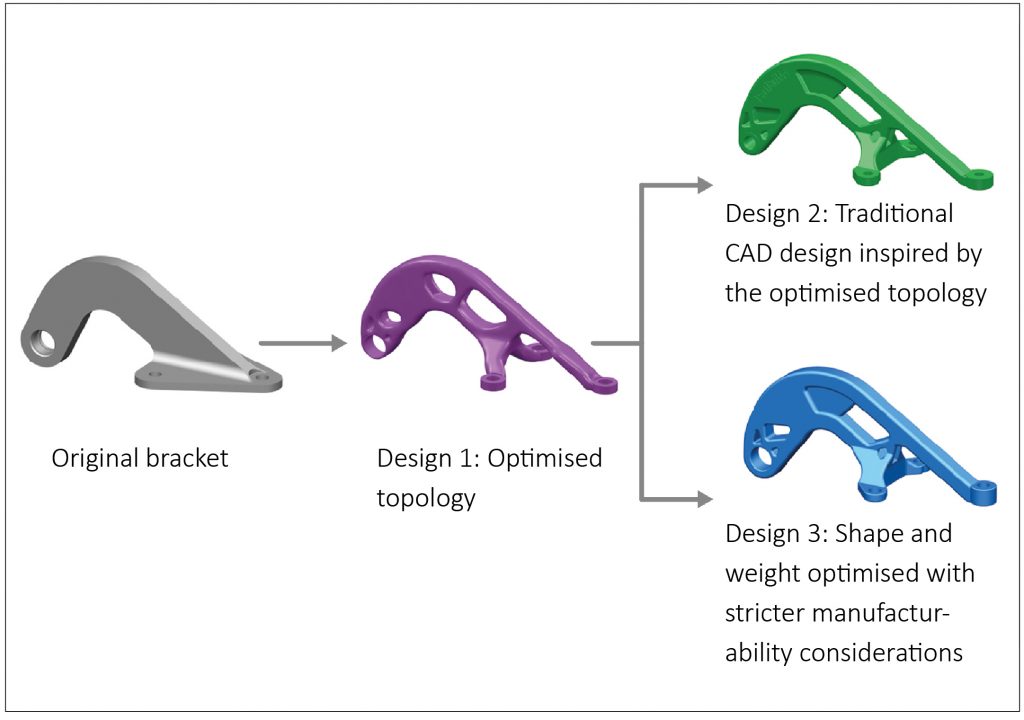
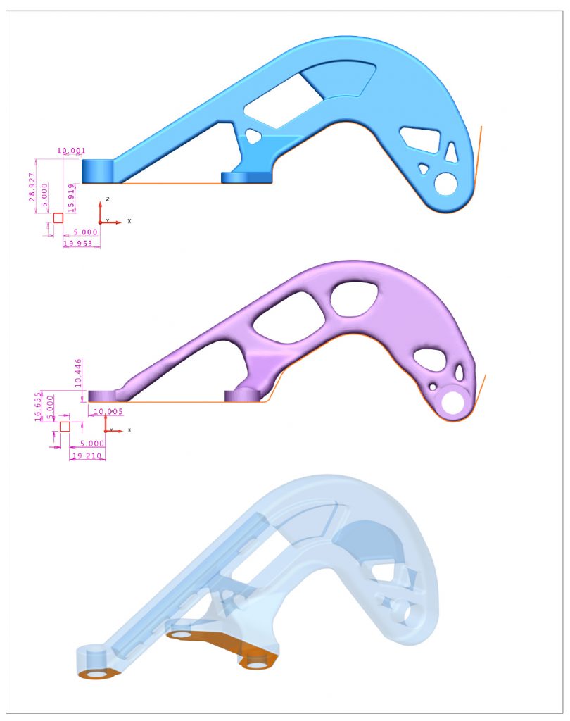
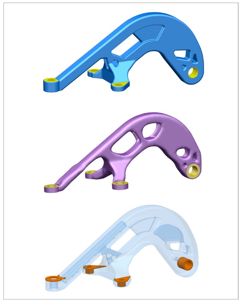
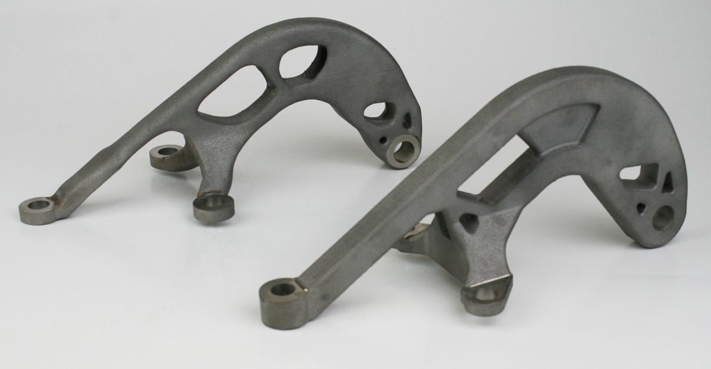
We took the design load cases and part requirements of an existing hinge bracket for an airbrake (see Fig. 2, top). The current design weighs 430.3 g and was conventionally machined from solid titanium. Working with colleagues at Autodesk, a topologically optimised shape was created using Inventor’s Shape Generator tool. The redesigned part, called Opti-Opti (Design 1), respects the weight and stiffness constraints required by the airbrake (Fig. 2, middle). The shape was smoothed and re-simulated against the original loads using Fusion Simulation to verify the lightweight design, which must hold while the brakes are being applied at 850 mph. The optimised design, when realised, would deliver a 22% mass saving compared to the original, machined-from-solid bracket.
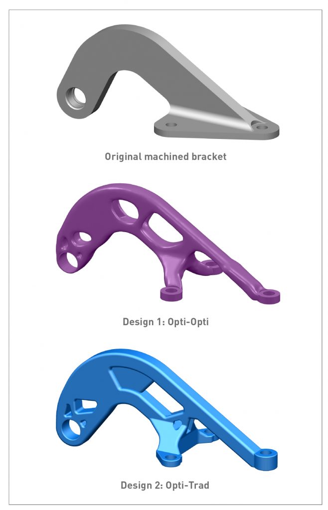
However, with its crow’s feet design and cavities, it is not an ideal shape for manufacture. A number of the surfaces cannot be machined, meaning that some of the AM support fixtures would be impossible to remove and it would be difficult to achieve the required surface finish. Additional thought about the manufacturability of the optimised shape and its effects on downstream processes was therefore required.
Consequently, the Opti-Opti shape was used as a design template to produce a geometry that is more acceptable for manufacture. This resulted in the Opti-Trad (Design 2), a traditional CAD design using topology optimisation to explore design concepts (Fig. 2, bottom). Inventor’s mechanical analysis and simulation tools were again used to verify that the new design meets load and stress requirements.
The as-designed mass of Opti-Trad was 438.3 g, a 2% increase compared to the machined-from-solid bracket. Although the shape inspiration of the optimised design has been kept, the Opti-Trad foregoes all the mass saving initially seen. There certainly is a happy middle ground to be achieved and this is discussed over the following pages.

With our final designs approved for manufacture, we moved on to process planning, manufacturing preparation and production. These are iterative phases: you cannot define a process plan in isolation before moving on to preparation and production. If only it were that simple. In reality, the process plan must be adapted to reflect the real decisions and compromises that have to be made as you consult with individual process experts and embark on each step.
Inexperience is, without doubt, the worst enemy of anyone who is starting to combine AM with other manufacturing processes. We were not immune to this and our learning was accompanied by some painful experiences. Ultimately, as we gain more experience of combining AM into the mix of manufacturing processes and as more CAE software tools become available, we will see more sharing of best practices and the normalisation of these iterative steps.
As a side note, the mindset and the actions involved in this iterative process of planning and manufacturing preparation will differ slightly, depending on which material (titanium vs. aluminium vs. steel, etc.) you are working with, which AM technology (SLM, EBM, DED etc.) is being used, the quantities, and the strictness of the industry standards with respect to part and process quality (aerospace vs. Formula 1 etc.).
Process planning
Process planning is without doubt the most important step. We have identified eight key issues that the process planner must consider. This is not an exhaustive list but it is a good starting point for any project. Planning is iterative and a comprehensive process plan emerges only by consulting with individual process experts and thinking about how each step in the process affects every other step. The principle of ‘rinse and repeat’ applies here. The key considerations of process planning include:
- Manufacturing and product requirements
What standards does the product have to conform to? This can include, but is not restricted to, material, quantities, tolerances, mechanical and surface properties. - Technology choice
What technologies are required to realise the requirements – additive, subtractive, or other processes in some combination? - Process choice
What processes are needed for each technology? This can be AM-powder bed, milling, turning, wire EDM or other processes such as thermal and surface treatments. - Machine choice
What machines are needed and available for each process choice? This can be laser/EBM-based powder bed AM, 3-5 axis milling, mill-turn, turn and/or submerged wire EDM machine. - Sub-processes
What sub-processes are involved for each of the process choices? This can be face or surface milling, drilling, boring, threading, wire cutting, powder and support removal etc. - Setups
What set-up does each machine, process and sub-process need? For example, three setups on a 3-axis mill or only one if a 5-axis machine is used. - Work holding
How will the part be held and fixtured in each setup? Perhaps the baseplate or some surfaces on the part itself are suitable, or it may be the case that standard clamps are enough. Alternatively, special machining fixtures may be required. - Execution sequencing
What is the execution order of each operation? It could be: first build on a powder bed machine, then clean excess powder, then machine holes with the parts still on the baseplate, then wire EDM a profile, or some other more complex mix of operations.
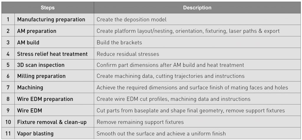
With these considerations in mind, our starting point for Designs 1 and 2 was to build both brackets, heat treat to relieve stresses, machine only the interfaces and holes while on the baseplate, wire EDM the bottom profile and clean up. This is just the high-level view of the manufacturing processes that we would have to use. It does not provide the level of detail necessary for a comprehensive plan. To achieve this, we had to walk through each process to see where things overlap and where potential problems might occur.
Compromises are always required and this activity highlights where these compromises had to be made. For example, if we had decided to machine while the parts were still attached to the baseplate, this would have implications on the downstream processes. Surfaces of the baseplate could be used for clamping during machining, but we had to think about how the parts would be nested relative to the baseplate, which surfaces could be used as datum references, tool access and so forth.

Conversely, we could have decided to wire EDM the parts from the baseplate before machining. In such a case, we would have had to worry about how to hold the parts and how to obtain datum references. It may even have necessitated the production of special machining fixtures to hold the parts.
This highlights how seemingly simple decisions have significant downstream impacts on the preparation stage and on subsequent processes. There are also cost implications to consider. In some cases, alterations to the original design may be required to accommodate the chosen manufacturing process.
Decisions about post-build processes need to be made as early as possible, even as early as the design stage. A true understanding of how each decision will affect the build means that involving each member of the supply chain, from the designer right through to those involved in the finishing processes, is critical to success. Unfortunately, there is currently a lack of cross-pollination and interaction between AM experts and other manufacturing experts, which makes this process more difficult. Our final process plan is shown in Table 1.
Manufacturing preparation
There are many parallels to be drawn between what is typically done for castings and what is needed for AM. Since cast parts always require further processing, one of the golden rules of casting is to consult with each process expert before finalising the design for manufacture.
Many casting foundries have complementary processes in-house, since processes such as heat treatment, shot blasting, machining, tooling, polishing and coating, as well as non-destructive testing, are commonly used in combination with casting to produce finished products. It has taken years to build this expertise and production is guided by industry standards and best practices, allowing casting to sit as a fundamental manufacturing process.
The same expertise and understanding of multiple processes is required by those involved in producing metal AM parts, particularly when we speak about manufacturing preparation. Manufacturing preparation means thinking about each process and sub-process in the planning phase to visualise how they impact the final part. These impacts are countered by applying design for manufacture and manufacturability principles.
At Delcam, we call this activity Modelling for Manufacturing (MfM). This activity has a pivotal role in minimising throughput time, the number of setups and the pitfalls of each process, while maximising part fidelity and the benefits of each process. Practically speaking, this can mean transforming the final CAD geometry into a deposition model, which is typically called the near net shape (NNS). This transformation usually involves simplifying or suppressing features that cannot be created satisfactorily using AM and adding features such as fixtures and datum references to aid downstream processes.
Consideration must also be given to platform layout, part orientation and the data export from the preparation environment to the machine. For our brackets, preparation involved the following: creating the deposition models, preparing for wire EDM, milling, additive, work holding and other processes.
Deposition model
Creating the NNS is often overlooked – or only done partially by those using AM to create metal parts. What is more, it is not clear who should be responsible for doing this – the designer/customer or the machine operators. Any build project needs to clarify this responsibility and confirm its completion.
To make another parallel with casting, typically the final part geometry is created by the customer needing the part. Subsequently, the relevant MfM rules are applied to create a NNS that accommodates the needs of casting and subsequent processes. This can mean adding excess stock material for machining, draft angles and part identification, defining parting lines, managing hot spots and compensating for shrinkage, to name but a few.
If the customer has the capabilities and expertise, they will undertake this activity. Otherwise it is done in collaboration with the casting foundry. Consultation is key here; otherwise, the likelihood of mistakes is very high. MfM rules must also be applied to create the NNS for AM. However, such rules are scarce or incomplete and typically are not sufficiently far reaching to cover the complex multi-process requirements of combining AM with other manufacturing processes.
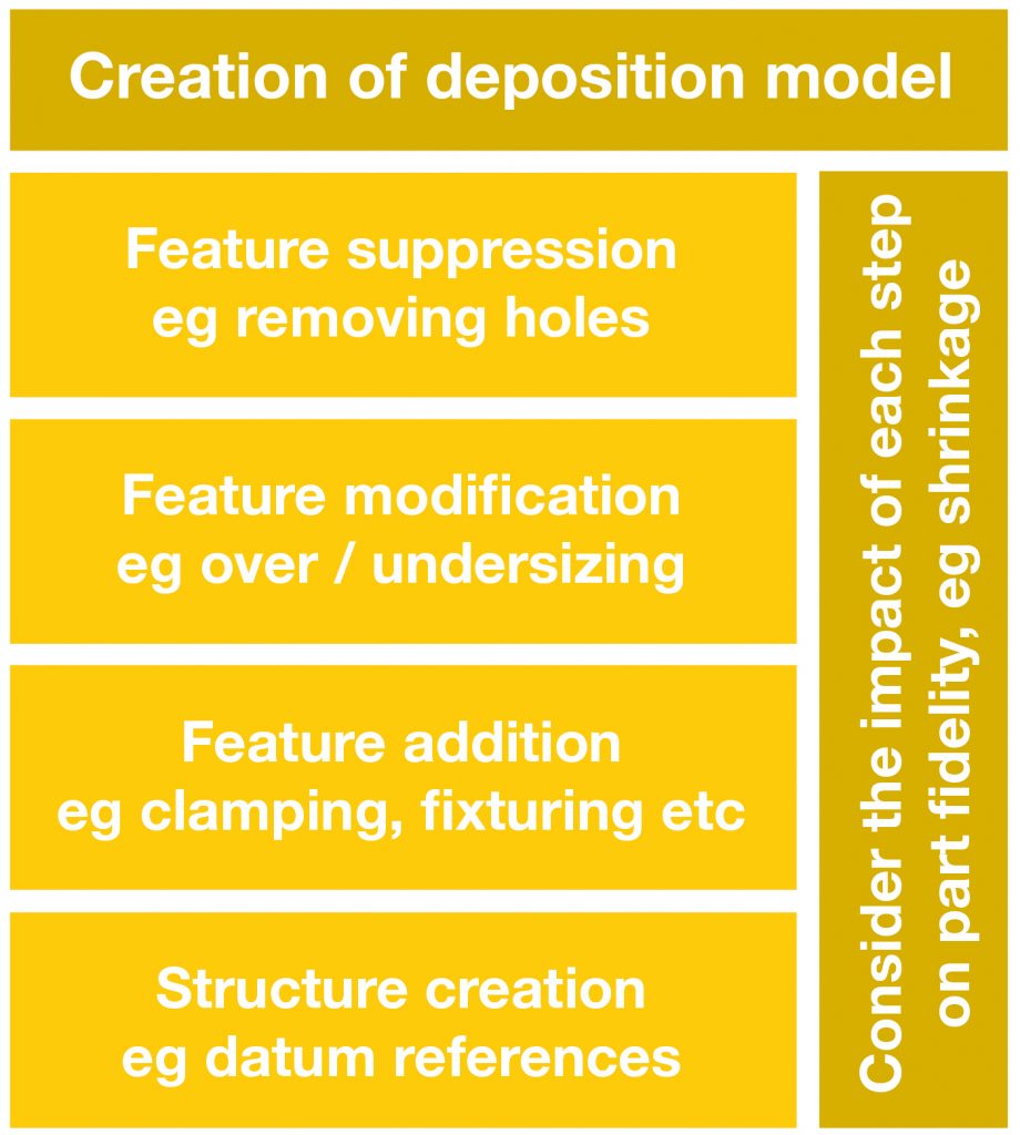
In our experience, creating the NNS for AM typically involves the four actions outlined in Fig. 4. These actions cannot be carried out in isolation but must occur in the context of each process and sub-process involved and consideration given to their interaction. For these brackets, we used our MfM software, PowerSHAPE, to complete the required direct modelling tasks, such as feature suppression and feature modification. The deposition models emerged as a combination of all the impacts and decisions taken while preparing for wire EDM, milling, additive, work holding and other processes. As we go through the preparation for each process below, it will become clear where these actions are performed and in which context.
EDM preparation
Preparing for wire EDM is challenging because there are strict conditions that must be satisfied, leading us to ask ourselves the following questions:
- Is there enough additional stock material to cut through without damaging the parts?
- Are the surfaces appropriate for EDM?
- What setups are necessary?
- How do we orientate the parts so that cutting does not damage the baseplate or other parts on the platform?
- What cutting profiles are needed?
- How can datum references be obtained and how reliable will they be?
- Will any loose powder be released that could interrupt the cut?
- How can cutting information and surfaces be communicated effectively?
The answer to some of these questions will have a significant impact on how the AM preparation is performed, particularly part orientation and nesting. This demonstrates how the individual processes are intricately linked.
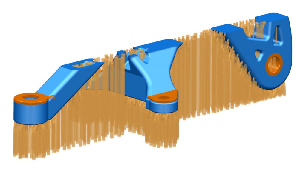
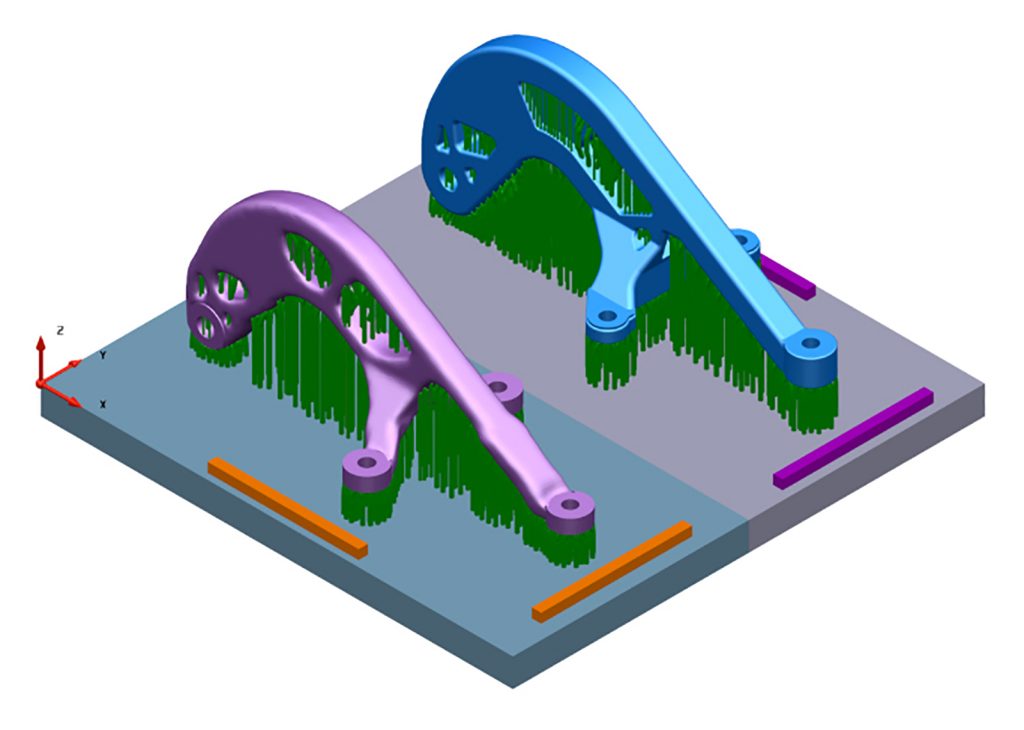
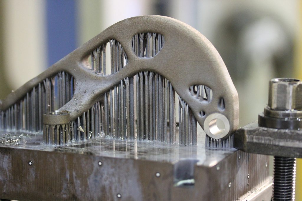
Asking these questions for our brackets led us to add 0.2 mm stock allowance to surfaces that would be cut by wire EDM. These surfaces are shown in orange in Fig. 5. The cut profiles, shown in relation to the reference datum bar, will create the shape of the final part. This step will also remove a large amount of the support fixtures (Fig. 6).
As can be seen in Fig. 6, long rectangular bars were added to the baseplate as datum references for wire EDM. They were also used to set XY alignment of the part. These reference bars are aligned with the parts rather than the baseplate, meaning the part can be machined correctly even if the baseplate is misaligned. Of course, side effects of AM such as shrinkage should be accounted for, as these could change the dimensional accuracy and invalidate the datum references. This is discussed in more detail later.

Finally, the wire cut path should be carefully defined with thought given to the order of operations. This should prevent additional geometries such as datum bars from being damaged or accidentally cut before they need to be used by another process.
Milling preparation
To mill these brackets, we used a 5-axis machine with standard clamping and PowerMILL CAM software to generate the toolpaths for milling the surfaces and drilling the holes. ‘Gentle’ machining was specified for the part as we were uncertain how the support fixtures would react to machining. The fixtures might be strong enough to withstand machining loads in the z-axis but might not be strong enough when the loads are in the x-axis or y-axis. The main considerations that were of concern to us in relation to machining were:
- Is there enough additional stock material to cut through without damaging the part?
- What is the material condition and will it cut properly?
- What machine tool and cutting tools are necessary/available?
- What setups are necessary?
- How will the parts be held (work holding)?
- What cutting strategies (toolpaths) are necessary?
- Are the toolpaths safe and collision-free?
- What data are necessary for the machine?
We machined the interfaces and holes while the part remained attached to the baseplate. These surfaces are highlighted in yellow in Fig. 7. For the holes, we added 1.5 mm of additional stock and 1 mm was added to the planar faces.
AM preparation
Preparing for AM in this multi-stage process typically requires numerous iterations. The interactions of the processes culminate here because this is where every aspect needs to come together and be accounted for before the build starts. If anything needs to be changed after the part has started or finished building, this could mean scrapping the part. In order to prepare for AM and its interaction with the other processes, we asked ourselves the following questions:
- What is the build orientation of the parts?
- How should parts be nested (i.e. positioned relative to one another)?
- How does nesting affect dosing factors and powder utilisation?
- What type of recoater blade is to be used and how will that affect the parts and support fixtures?
- What additional geometries need to be built – datum references, travel specimen etc?
- What type of support fixtures are needed and where? Important considerations when designing support fixtures include the type of process and material, the size of the part, managing heat/distortion/stress, melt pool stability and managing part geometric fidelity
- How will the part be exposed? Important parameters include scan strategy, laser paths/power/focus/speed
- What data format does the AM machine need?

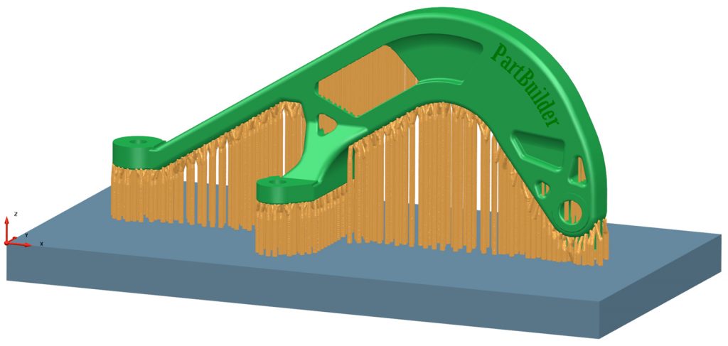
PartBuilder, our AM preparation software, was used for orientation, nesting, fixturing, the creation of reference data points and the exposure data for the laser (slicing and hatching). It was also used for exporting build data specific to the machine used. The process plan tells us to machine Design 1 and 2 parts on the baseplate, so this means the part orientation is already constrained. Due to the size of the parts and the build envelope of the machine we used, only two parts could be placed on the platform. This determined the part nesting.
Thinking about machining issues such as clamping and cutting tool access forced us to use two half baseplates, of 250 x 125 mm each, instead of the standard single 250 x 250 mm baseplate. This allowed us to build each part on its own plate, simplifying heat treatment, machining tool access and clamping as well as workpiece handling.
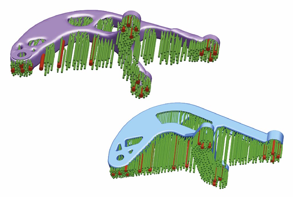
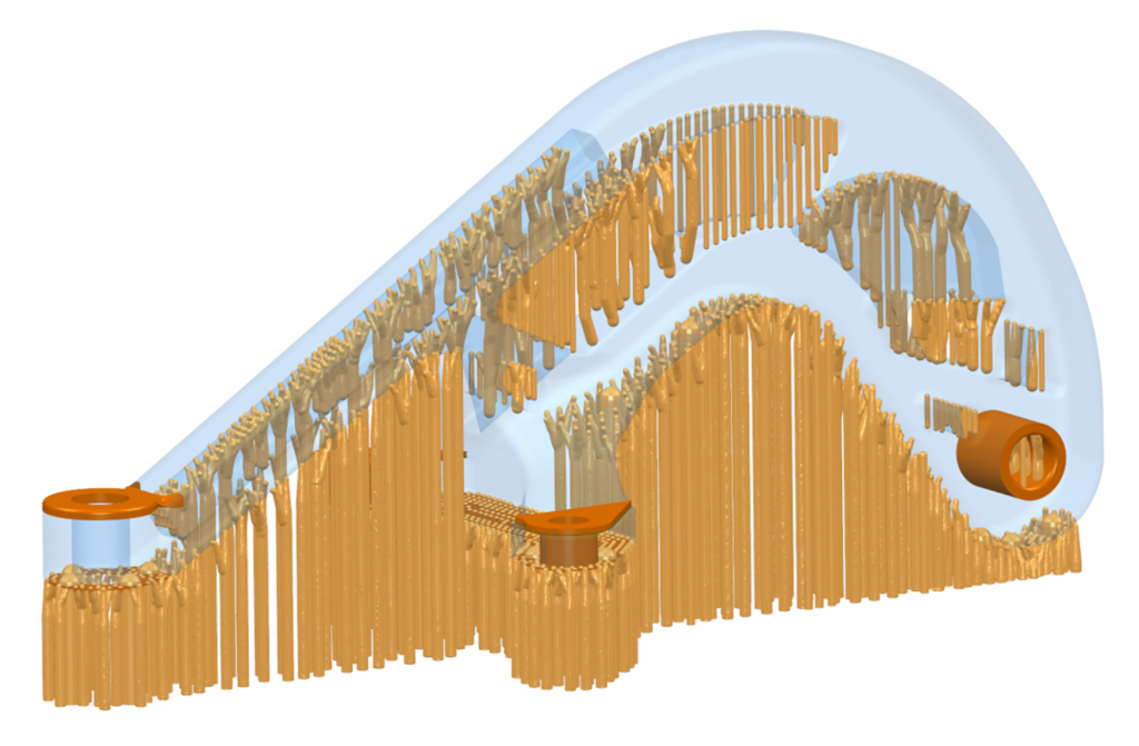
The next task was to create general support fixturing. PartBuilder can determine where fixtures are necessary, so we used it to automatically generate the majority of support fixtures (approx. 80%) required for the build (Fig. 8). For this build, we were working with titanium, a hard recoater blade and machining on the baseplate. However, the software cannot yet account for these variables. This requires manual intervention from an engineer with an understanding of the nuances of both AM and the subtractive processes to identify where problems could occur and take measures to prevent them.
Anticipating distortion and how this might impede the recoating action, special bracing support fixtures were added to critical areas (Fig. 9). At the layer height shown in Fig. 9 there were a number of individual overhanging material islands which had to be treated independently to prevent distortion. The number and size of exposed sharp edges in the recoating direction changes as the part is exposed and before individual islands of material join up. Therefore, additional cylindrical fixtures were added at key locations (the red columns in Fig. 8) to counteract cutting forces during machining.
Work holding preparation
Work holding for each set-up and each process should be given particular attention in order to avoid unexpected surprises. For each process, sub-process and their associated set-up, we needed to consider the following:
- What type of work holding/clamping do we need and where do we put them?
- Do we need to build additional geometries using AM, specifically for clamping?
- Do we need to design and fabricate special machining fixtures?
- What impact do these additions have on upstream and downstream processes?
For machining Designs 1 and 2, only a single setup was used to machine all the holes and interfaces on the 5-axis milling machine. The baseplate was directly used for clamping, so no additional preparation was necessary.
It is also important to think about the sequence of operations with respect to work holding, as compromises could be necessary. For example, the nesting decision for AM will affect how and where clamps for milling can be placed if the baseplate is to be used. In this case, nesting should not interfere with clamping surfaces. Subsequently, and more importantly, when a part is separated from its baseplate, special care should be taken to ensure that clamping surfaces are available on the part and that there are surfaces appropriate for use as datum references. If the part has to be separated from its baseplate and is not a regular prismatic shape, then special machining fixtures will be required to hold the part.
Other processes
The remaining ancillary processes include heat treatment, surface treatment, manual fixture removal and any other steps identified in the process plan. Though they may not require any preparation, it is important to consider them and ask what additional geometry or data is necessary for these processes, and how should important information and work instructions be communicated.
Our process plan called for vapor blasting of the surfaces, so we had to communicate that machined surfaces should be masked to prevent damaging the as-machined surface finish.
The NNS that emerged for the Opti-Trad bracket after all the preparation steps had been followed is shown in Fig. 10. The final platform layout after nesting is shown in Fig. 11. Bracket Designs 1 and 2 are now ready to be built.
Preparing design 3
As stated earlier, the Opti-Trad bracket is slightly heavier than the original bracket after applying traditional CAD design techniques. Going further than simply using the optimised bracket as a shape inspiration, stricter MfM and manufacturability considerations were applied while maintaining the weight saving benefits of the topology optimised bracket. To arrive at this particular design, we started with the Opti-Trad bracket (as shown in Fig. 2, bottom) and changed the manufacturing objective from machine only the interfaces and holes while on the baseplate to machine all surfaces. This strict requirement means that all geometric elements added during the preparation stage must be removed. It also highlights the need for compromises in the part design stage to account for the limitations of the AM process.
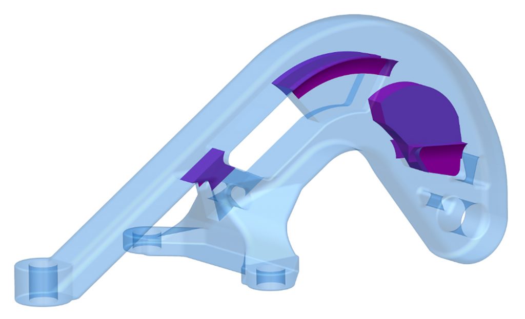
Design changes were necessary to account for some of the manufacturability concerns. The purple additions shown in Fig. 12 are extra geometries constructed to eliminate the need for support fixtures in those areas as well as to close hollow cavities, which will be impossible to clean up.
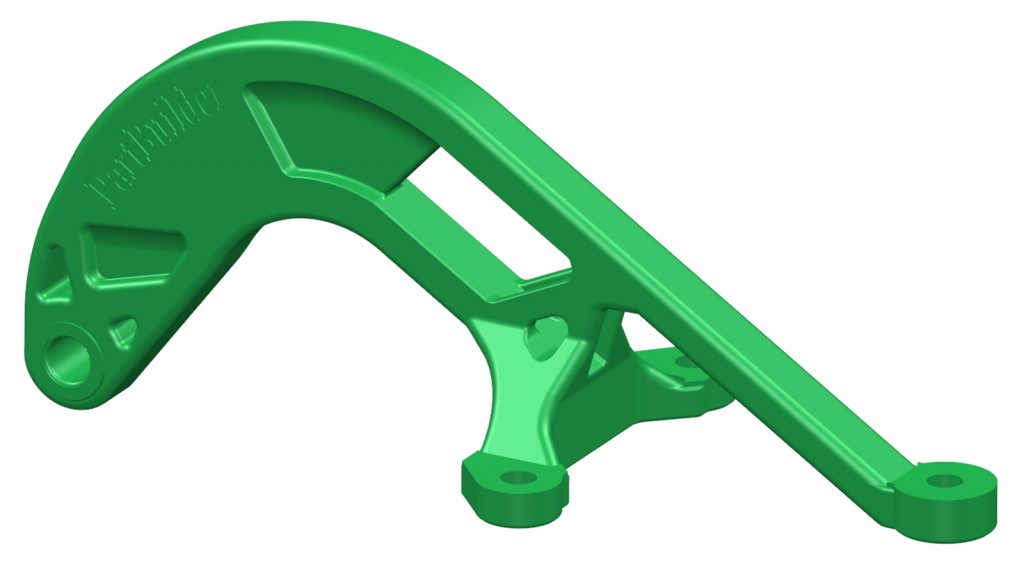
The final result is shown in Fig. 13. Accounting for performance, shape and mass gains originally obtained by topology optimisation achieves a 19% mass reduction compared to the original machined-from-solid part. Adding a high manufacturability constraint forced us to think even more about the end to end processes. The final platform layout after nesting is shown in Fig. 14. Bracket Design 3 is now ready to be built.
A question asked when casting was maturing and which is very relevant today about AM is: can we define best practices/rules for experts and non-experts to make effective and impactful changes to part geometries without compromising part fidelity or negatively impacting manufacturability?
The activities performed before the AM build began, along with supporting software, are summarised in Fig. 15. This process includes design, topology optimisation, simulation, planning and all preparation activities.

Production
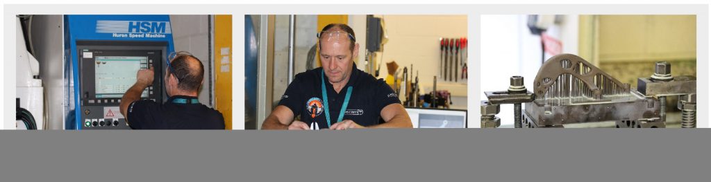
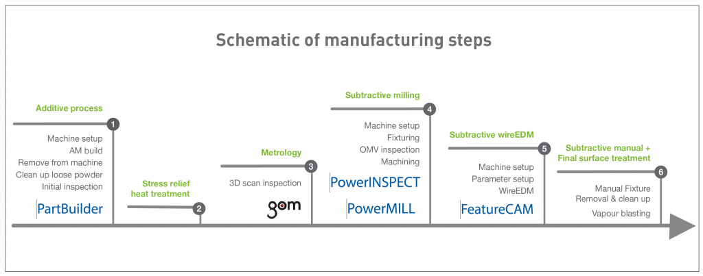
Production of the brackets revolved around physical actions to realise the process plan. Actions included setting up each machine, obtaining appropriate datum references and alignment, performing the necessary actions such as cutting or scanning until the final products emerged. Figs. 16-26 show the production stages for Designs 1 and 2 only.

Additive build and heat treatment
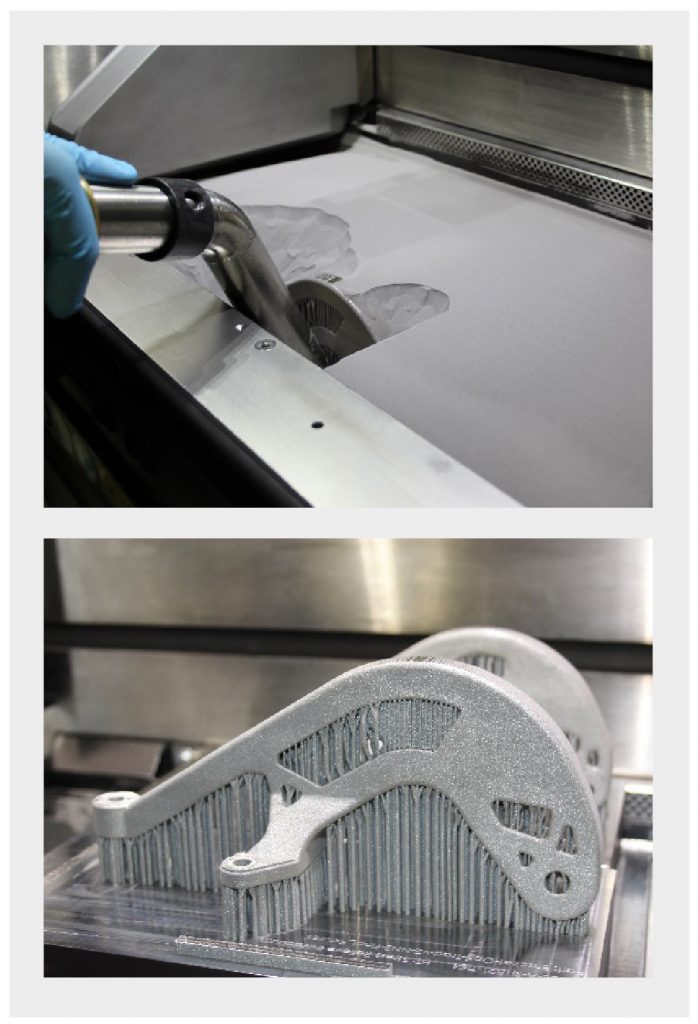
- AM machine set-up: manually installing and checking flatness of baseplate, manually cleaning the glass aperture of the laser, manually filling in powder and filling in ‘holes’ between the baseplate (Fig. 16)
- AM build and reveal: manually removing powder with a vacuum to reveal the parts (Fig. 17)
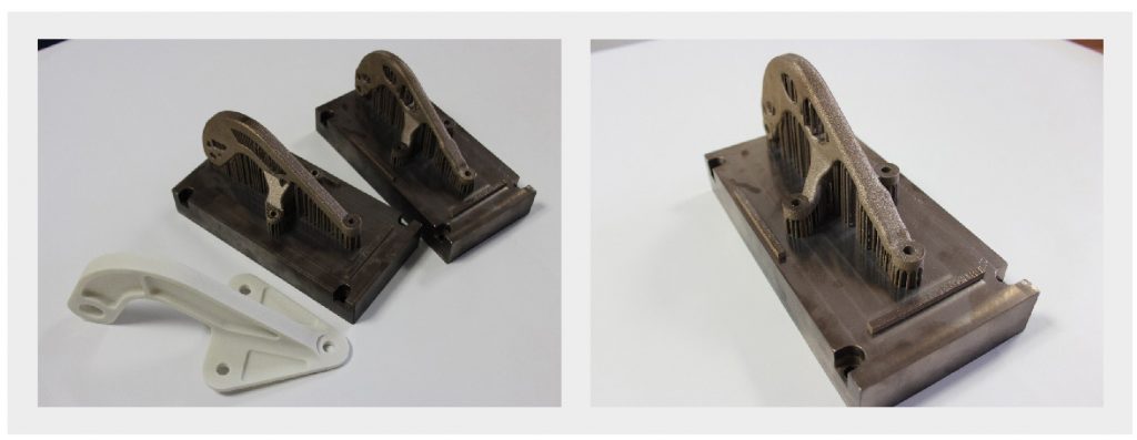
- Post heat treatment: brackets after heat treatment with a plastic mock-up of the original bracket (Fig. 18)
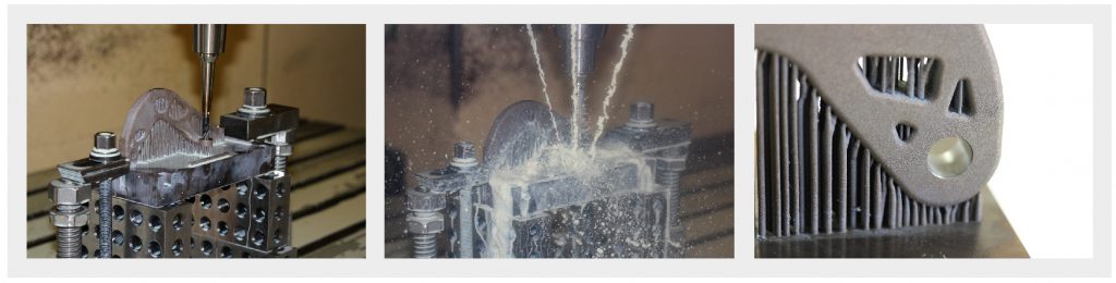
Metrology and machining
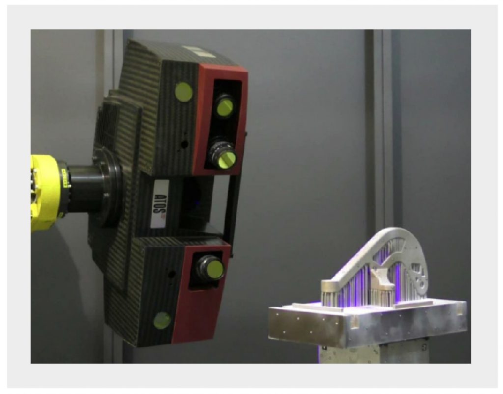
- 3D scan inspection: controlling part dimensions with 3D optical scanning (Fig. 19).
- Machine setup & Fixturing: Setting up the milling machine by defining part position and alignment, clamping and programs before cutting (Fig. 20).
- Machining & On-Machine Verification/Inspection: Machining interfaces and holes, verifying and controlling part dimensions (Fig. 21).
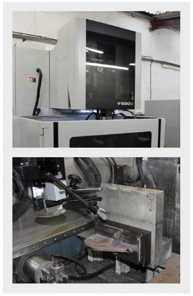
Wire EDM
- Machine setup & Fixturing: Setting up the wire EDM machine by defining part position and alignment before cutting (Fig. 22).
- Wire EDM to separate the part from the baseplate, remove the support fixtures and achieve final part dimensions on some surfaces (Fig. 23).

Clean-up and surface treatment
- Manual fixture removal and clean-up of witness marks (Fig. 24)
- Vapor blasting to produce a uniform surface finish. Machined surfaces and holes are masked to protect them (Fig. 25).

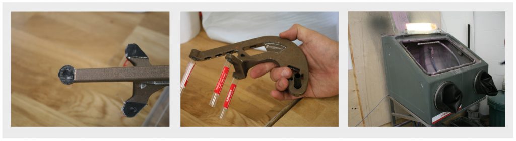
The final parts are shown in Fig. 26. The activities performed during the production/execution stage are best summarised by Fig. 27, along with the supporting software tools used.
Reflections on the process
Our experience in designing, optimising, preparing and manufacturing these brackets has left us with many topics to discuss and reflect on. The following examples illustrate the need to consider how seemingly small decisions taken at each step of the process can affect the later stages. Until we can freely share and understand the black arts and artisanal secrets of AM, the process will not become a standard technique within the manufacturing family alongside casting, forging etc.
Metrology and quality assurance
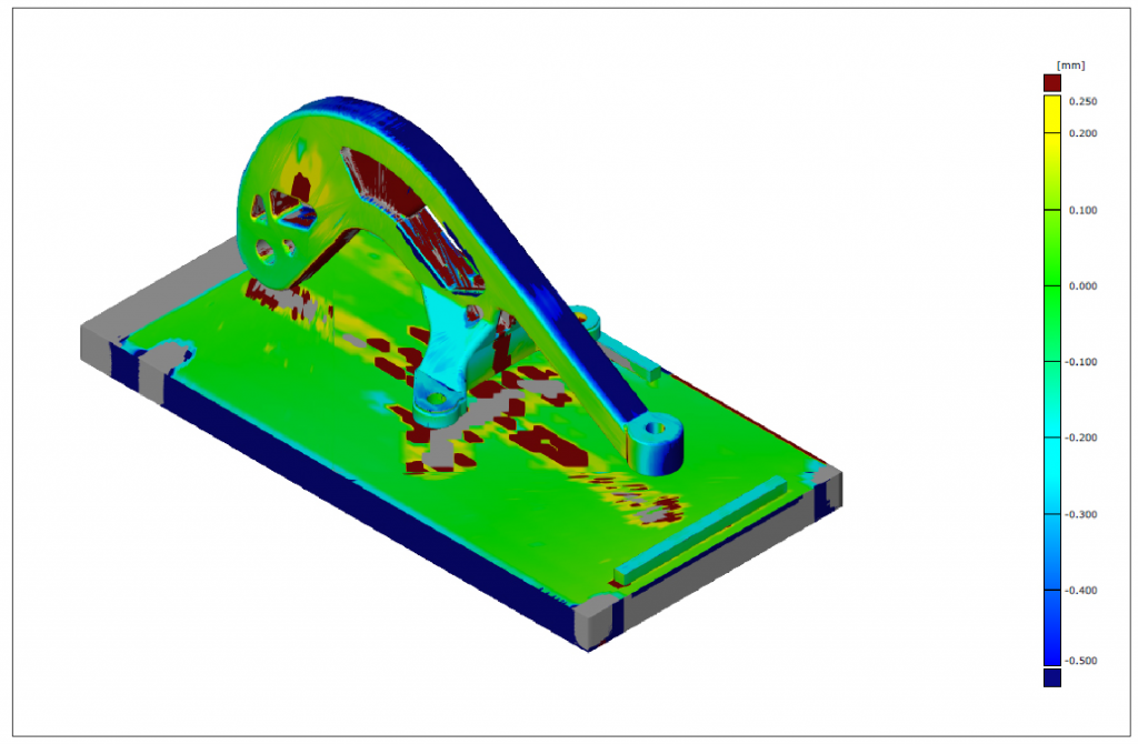
Following the build, we heat treated the parts in a vacuum to reduce residual thermal stresses. When the parts were inspected with conventional touch probing and optical 3D scanning, this revealed non-uniform shrinkage in some areas. Scanning also confirmed the extent of delamination illustrated in Fig. 29. This could have been as a result of the scaling factor used and/or the heat treatment. Regardless of the cause, one thing is clear – at this stage in the development of metal AM technology, we need to introduce more measurements and quality operations into the production process in order to understand what is happening to the part and how each process affects the shape. Since we only scanned these brackets fully after heat treatment, we do not know what the geometric fidelity was like immediately after building. Additional measurements steps before heat treatment and after machining would have allowed us to track the shape changes more accurately and adjust the downstream processes accordingly. Without absolute certainty, cutting the parts could have resulted in costly damage. Looking at the planarity of the three holes shown in Fig. 28, had we machined without first verifying positions, these features would have been incorrectly machined.
Until we are at a point where we can reliably predict the shape of parts, such measurement activities are critical. We must follow quality assurance guidelines offered by committees formulating manufacturing standards as well as discussing openly how to account for the peculiarities of Additive Manufacturing.
AM build: issues observed
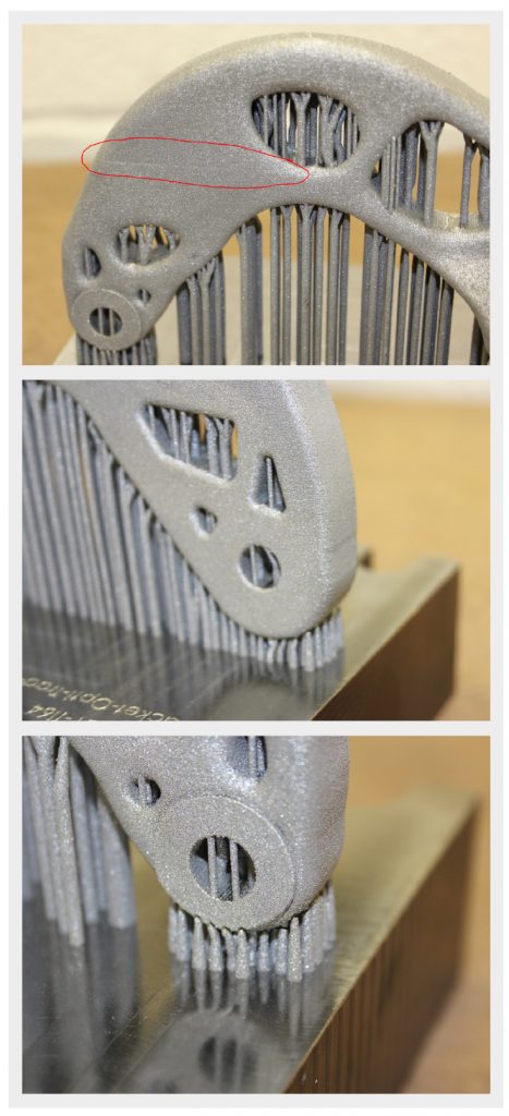
Currently, support fixture generation is one of the black arts of metal AM. Depending on the material, only the most experienced and knowledgeable AM practitioners are doing this successfully and even they have no way of knowing whether what they have prepared is going to work. At Delcam, we are acutely aware of this issue and it is in the industry’s interest to find a pragmatic solution. Despite considering a number of potentially problematic areas during the preparation of these brackets, we still encountered problems. “Titanium always finds a way to surprise” is a statement we hear often.
The support fixtures of our as-built parts were generally sufficient except around the back pivot hole where a separation between the part and its support fixtures can be seen (Fig. 29, bottom). This could be the result of high residual thermal stresses due to the shape of the part, uneven cooling rates and/or the large mass of material in this region. This fault had a number of downstream impacts. Firstly, a cosmetic error in the form of a horizontal line was observed on the Opti-Opti part (Fig. 29, top). Secondly, the part physically moved, directly affecting milling and wire EDM datum references as well as the positions of important features.
Additionally, consultation with the machine operators during the preparation phase raised questions about the efficacy of the trees and column support fixtures. The operators were not confident that they would be strong enough to withstand the machining loads while the holes were drilled into the solid material. As a compromise, the holes were undersized in the NNS before building, meaning that they could be milled to the correct size rather than drilled into the solid material. Additional stiffening fixtures were also added after understanding the operators’ concerns. This is particularly important because using block supports is commonplace in AM, as is the practice of removing features such as holes to achieve more accurate positioning and tolerances. If parts are to be machined while still on their baseplates, the strength of these supporting structures should be assessed and provisions made to account for machining loads.
Compensation factors: build accuracy
How accurately parts are built depends on a number of factors. Through this process, we have uncovered a number of relevant factors for which published information is scarce.
Firstly, as a part is built, powder is transformed from loose powder to molten metal before solidifying. In each stage, there is a negative volume change that occurs, called shrinkage. This is a known thermal phenomenon. To counteract this, shrinkage compensation factors (SCFs) can be applied in order to change the nominal dimensions of the entire part. In casting there are established SCFs that are applied, depending on material, geometry and other considerations. However, as the complexity of cast parts increases, application of SCF becomes more complicated and requires careful consideration. Generally, experience, some guidelines and trial and error are frequently used. The emergence of casting simulation software to predict the extent of shrinkage and other thermal effects is helping to give more insight. It is not yet clear whether the factors and methods used in casting are directly applicable to Additive Manufacturing.
Currently, the shrinkage compensation factors used in AM and how they are determined is one of the other black arts and artisanal secrets. Usually the assumption is that there is homogenous shape deviation for a particular direction and therefore only a single SCF is applied to the nominal dimension in a given direction. This method is problematic because the effects of different geometric features, their sizes, locations and orientations are not taken into account. SCF based solely on the thermal expansion characteristics of additive materials are known to be insufficient when dealing with complex AM parts.
For shrinkage, the solution might be, as proposed by Ning [4] ,to compensate by changing process parameters or improved simulation and modelling tools, or applying careful distortion compensation. Whatever the solution, we need better understanding of the problem before new methods can be developed to rectify it.
Secondly, depending on how the machine has been calibrated, part dimensions can vary. Calibration factors, typically applied to XY dimensions per layer, depend on the machine and the defined build tolerance. Factors can also be varied from build to build, depending on the as-built dimensional requirements of a part. Since the part can be built slightly over- or undersized or exactly to CAD, special care and attention must be paid to dimensional accuracy requirements so that the part is built within tolerances.
Thirdly, the build strategy (and therefore the path that the laser follows as it builds the external and internal boundary contours of each layer) can have a substantial effect on the dimensional accuracy of the part. As each line is traced and melted by the laser, there is an effective welded track width. On these boundary contours, the part dimensions can be slightly over- or undersized or exactly to CAD depending on the build strategy and a parameter referred to as beam offset or beam compensation. Again, special care and attention must be paid to dimensional accuracy so that the part is built within the required tolerances.
Knowing about and discussing these important compensation factors can have a marked impact on the achieved dimensional accuracies of parts. For a machinist, for example, knowing the condition of supply of a part is paramount if they are to perform their precision finishing task well.
Part nesting: which way is up?
Everyone in the chain has their own priorities and is thinking about their individual step in isolation. In these bracket examples, the nesting angle of the parts (Fig. 30) was changed because the AM machine operator was not sure if he had enough titanium powder to complete the job. Consequently, the operator rotated the part 180° around its vertical axis as a means of bringing the highest portion of the part closer to the start of the recoater blade’s course. This change was not communicated and therefore the process plan was not updated.

Such changes are commonly made by machine operators when powder levels are running low. After all, titanium powder is expensive and having unnecessary powder stockpiles represents a substantial investment for sub-contractors. This important build decision was taken without consideration of the downstream processes and resulted in a number of issues.
First, during machining, surfaces that were required for clamping and work holding were noticeably reduced (Fig. 31). Compromises had to be made while setting up the milling machine to rectify this unexpected issue. The risk of collisions between the cutting tool and the clamps was suddenly increased because the CAD file and the machining work instructions no longer match the physical part.
Second, during preparation, it was anticipated that a hard recoater blade would be used. As such, if there was any distortion, there might be collision between the recoater blade and the part. To prevent this, special bracing support fixtures were added. During manufacture, however, a soft recoater blade was used to ensure a high probability of a successful build (the tree support fixtures used were not known to the AM machine operator and he had doubts about their effectiveness). Consequently, the parts were over-fixtured, resulting in additional material needing to be used and later cleaned up.
It is clear that, in any build project, the project manager (what we call the orchestrator) and the process planning team must be well versed in the ins and outs of AM and the other manufacturing processes. It is important to know and understand what the concerns are of each actor in the supply chain. It is only then that they would be able to mitigate any potential problems. Otherwise the actor will only do what makes their own lives easier, which may or may not be in line with the process plan.
The concern of the AM machine operator and his decision stemmed from the fact that he has no reliable way to know and effectively control powder use. There is a lack of tools to determine how much powder will be required for the entire build and to properly cover the exposure area of each layer without over or under dispensing powder. This is the dosage factor and some of the advanced systems available today are still only reactive, meaning that they compensate if powder is over or under dosed. Preparation software, such as PartBuilder could potentially be used to determine setpoints for the dosage factor of each layer and thus estimate powder need. Conversely, if the AM slice formats and machines were updated to support such setpoint parameters, this could improve the estimation of powder required for a build. Until the machines are able to do this or machines with powder conveyor systems are more commonplace, the machine operators have to guess and use their experience to determine what dosage factors to apply and when. Compounding this problem is the fact that the machine we were using, a top-of-the-range metal powder bed machine, cannot recover unused powder from its overflow bin during a build. Running out of raw material mid-build could mean the part would have to be scrapped if an identical batch of powder cannot be obtained. When a suitable powder is available, stopping the machine to restock powder levels can cause cosmetic errors, such as the visible horizontal line that formed across our part (Fig. 29). The commercial impact of lost production time and rebuilding parts could be costly.
Datum references and education
Additive parts are near net shapes and machining such parts is akin to machining castings or forgings, processes that also produce near net shapes. On such shapes, there are many ways to obtain datum references for setup and part alignment, but typically it is best if datum surfaces are features on the part. This ensures the highest reliability of the datum references. There is a lot of thought that goes into defining datum references and the associated work holding. These two important aspects are sometimes overlooked for AM and, even when they are not overlooked, they are incompletely provided. The cost associated with such oversight can be shocking.
For datum references, an observed practice in AM is to add blocks which are additional geometries built directly on the baseplate as seen in Fig. 6. To machine these brackets, we followed this same practice to see how different actors in our supply chain would deal with them.
For machining, we used Delcam’s Advanced Manufacturing Facility in Birmingham, UK. The operators there refused to use these surfaces because they did not trust them. This was simply because they were not attached to the parts and this was an unfamiliar technique for them. The operators involved have not been exposed to many additive parts. They simply used their tried and trusted conventional methods i.e. touch probing the holes in the part and orthogonal surfaces for alignment and positioning to achieve the best fit to CAD. For wire EDM, these blocks were used for alignment and positioning without question. The operators here are relatively more familiar with cutting additive parts.
Where possible, any part that is to be produced by AM and further processed with other conventional techniques should ensure that proper work holding and datum references are considered. If the part to be machined is non-prismatic, one benefit of AM is that datum blocks could potentially be added during preparation and built with the part. Once the blocks serve their purpose, they will need to be removed.
It would go a long way in fitting AM into the manufacturing family if we all spoke a familiar language. Where necessary, existing geometric dimensioning and tolerancing standards (GD&T), such as ASME Y14.5, should be applied to minimise misinterpretations and mistakes.
Traditional supply chain actors may never have processed additive parts, so they will simply apply conventional thinking and familiar methods. Decisions taken during preparation must either be carefully communicated with them or already be in line with what they expect to see. As we grow as an industry, it is to the benefit of the existing manufacturing actors and the new actors to educate each other.
Hardware: build volume
The quoted AM machine build volume, particularly the build height, is not a static value. Depending on the material that is to be processed, the thickness of the baseplate might need to be changed to prevent distortion when working with bulky titanium parts for example. This increase in baseplate thickness reduces the effective build height of the machine. Properly communicating this change in size to customers will go a long way to preventing unwanted surprises such as preparing a large part only to find out that the maximum part height cannot be attained due to the thicker baseplate. Doing this will increase transparency between machine vendors and machine users.
Predictability & repeatability
There are many variables to consider when working with metal additive processes from planning and preparation decisions to laser exposure parameters, material sourcing, thermal impacts and the limitations of AM machines. These factors together have a marked effect on the predictability and repeatability (P&R) of the as-built additive parts. Without measurable P&R, more uncertainty is introduced for later stage processes like wire EDM and machining. Even if problems are not easily corrected, being able to consistently reproduce and quantify them is very important.
Currently many AM practitioners, ourselves included, follow a trial and error approach. First build a part, see what goes wrong and apply lessons learnt to improve the next build. To quote Steve Hobbs, Development Director at Delcam, “It’s not acceptable to make four parts and get only one good one. We need to be able to do better than that.” This is not only wasteful and inefficient, but it represents a huge obstacle to taking AM beyond rapid prototyping. It is clear that, as an industry, we need more effort and tools to identify potential problems.
It is encouraging to see groups like 3DSIM, Additive Industries and Sigma Labs [5] working on addressing known quality assurance problems across the AM process chain. Indeed, we do not have years to wait for answers to these issues. We must take a realistic look at the problems to come up with pragmatic, reliable solutions for them. The lack of process understanding and other issues precluding metal AM from widespread use are difficult enough, but, when we add the complexity of multi-process production, the picture appears daunting. It is going to take an industrial effort to realise the true potential of this exciting technology. Everyone from process experts, planners, designers, machine makers, CAD-CAM vendors, supply chain actors and standards bodies are going to have to play their part. From what we have learnt, we know that Delcam and Autodesk also have a part to play.
Software
Going through the complete chain, from design and simulation to planning, preparation and production, shows that the current tools can enable additive and subtractive manufacture of quality metal parts. There is still work to be done to improve some of the workflows along the data chain to make them more coherent and seamless. This coherence is essential in order to increase productivity and quality assurance. We want to give practitioners the ability to realise their designs and ideas. If those designs are to reach production, they must be verified and prepared digitally in a safe environment. They should be able to predict problems and resolve them before ever going onto a machine. It is better that they see the failure in a software environment than in real life, where costs and consequences are much higher.
Thinking beyond AM, CAD and design, which are being covered by the 3D Manufacturing Format Consortium (3MF), it raises the question: what about the interaction of AM with other manufacturing processes? Drawing an analogy with the building and construction industry and the revolution seen there with the widespread use of BIM (Building Information Modelling), the author wonders if manufacturing, including additive, needs its own information model?
Conclusion
We started by looking at the role of software within the process chain. By working with various bracket shapes from design all the way through to manufacture and post-processing, we explored what is currently possible with the available tools and processes at our disposal. The potential of how software can be used to enable the additive and subtractive manufacture of production quality metal parts is discussed and the primary conclusion that we can draw is that there is still some work to be done if Additive Manufacturing is to reach its full potential. Everyone from process experts, planners, designers, machine makers, CAD-CAM vendors, supply chain actors and standards bodies are going to have to be involved to truly enable this exciting technology.
Author
Kelvin Hamilton
Project Engineer R&D Projects Delcam, Birmingham, UK
Email: [email protected]
Delcam
Delcam is one of the world’s leading suppliers of advanced computer-aided manufacturing (CAM) software. Headquartered in Birmingham, UK, Delcam’s range of design, manufacturing and inspection software provides automated CAD/CAM solutions for a variety of industries, ranging from aerospace and automotive to toys and sports equipment. The company has more than 30 offices worldwide and approximately 700 employees. www.delcam.com
Autodesk
Autodesk is a leader in 3D design, engineering and entertainment software and acquired Delcam in 2014 as part of its expansion into manufacturing and fabrication. From additive to subtractive manufacturing and other related technologies, Autodesk now has the pieces needed to truly realize the Future Of Making Things for everyone from a maker to a major manufacturer. www.autodesk.com
References
[1] 10 Valuable Lessons from an Additive Metal Part, Article From: 10/30/2015 Additive Manufacturing, Peter Zelinski , Editor-in-Chief, www.additivemanufacturing.media/articles/
[2] [http://goo.gl/xTUFFK – link to WEF report]
[3] For more information about the Bloodhound SSC’s air brakes, see www.bloodhoundssc.com/news/airbrake-motion
[4] Ning Y, Wong Y, Fuh JY, Loh HT. An approach to minimize build errors in direct metal laser sintering. Autom Sci Eng IEEE, Trans On 2006;3:73–80.
LAST MONTH’S MOST-READ ARTICLES


