


A story of failure and success in metal AM: The reality of developing a titanium bike part
Metal Additive Manufacturing promises to enable smaller organisations to compete with global corporations in the development of new products. Expensive tooling and traditional production lines, it is suggested, need no longer be a barrier to market. As US-based designer and engineer Spencer Wright reveals in this insightful report, the reality of developing a low volume AM titanium part for production exposes a number of challenges that the industry needs to overcome if it is truly able to serve a new generation of product developers. [First published in Metal AM Vol. 1 No. 3, Autumn 2015 | 15 minute read | View on Issuu | Download PDF]

Two years ago, I began the slow and surprisingly dramatic process of developing a product for metal Additive Manufacturing. I had moved to New York City not long before and MakerBot and Shapeways were dominating the hardware scene there. There was a lot of talk about distributed manufacturing, and more and more real world examples of design optimisation software being used. For the first time in my career, I felt a growing interest in industrial grade problems. I was excited.
I’m a self-taught engineer. My background spans project management, product development, and a ton of hands-on experience in conventional manufacturing. I’ve worked in a narrow range of industries, but in general my interest has been in engineered, mechanical consumer products. I like systems – assemblies that add up to more than the sum of their parts. So, while Fused Deposition Modelling (FDM) and Selective Laser Sintering (SLS) were appealing because of their ability to speed up model and tool making, it was only when I saw the aerospace and medical uses of metal powder bed fusion that I became really excited for 3D printing as a manufacturing method.

I’m also a cyclist. I grew up around bikes, and managed a small shop during college, and for a few years I owned a small business building custom bicycle frames. While I left the cycling industry years ago, cycling (and bicycle design) has remained something of a fixture in my life. So when I started researching this new class of processes – ones which essentially amount to welding parts together from titanium powder – my mind went to the application that I knew well – bicycles.
As potential markets for metal AM go, high end road cycling is an excellent candidate. Reductions in weight and wind resistance are incredibly valuable. Custom, bespoke designs are prized. Sales cycles are relatively short, making just-in-time production attractive. Customers of high end bikes tend to have buying habits that are price inelastic; an expensive new product that offers genuine benefits can survive regardless of its price tag.
The seatmast topper
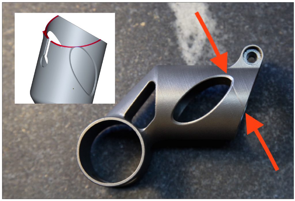
The part I’m building is a seatmast topper for high end road bicycles (Fig. 1). At about 60 g, it’s fairly lightweight. It’s also relatively small and fits easily within nearly every DMLS machine’s build platform. Because of its function (seatmast toppers are used to hold a bicycle saddle onto the frame) its structural requirements are fairly predictable. These factors, plus the fact that seatmast toppers are easy for almost any cyclist to install on their own bike, make it a good candidate for AM.
But that doesn’t mean it’s easy to print. The part consists of two cylinders, oriented 90° apart and joined together by a funnelled neck. The part’s wall thicknesses fall between 1 mm and 1.75 mm, roughly .039”-.068”, and it’s critical that these walls do not vary much in thickness; if they end up just .010” thinner, the part could be unusable (Fig. 2).
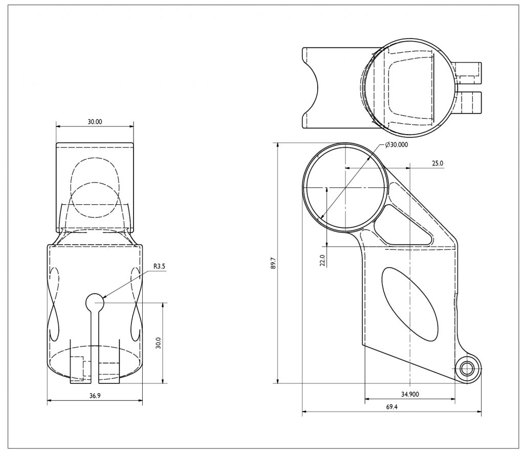
Harder yet, the inner diameters of both of the cylinders must be accurate and consistent. Again, variations of just .005” can have a big effect here – and if the cylinders end up with oval cross-sections, the part won’t work at all. Also, the titanium 6/4 that my part will be made of is notoriously prone to built-in stresses, meaning that we’ll have to be very careful setting up the build parameters and support structures to prevent the part from turning into a pretzel during the process.

First stage prototypes with the help of DRT Medical Morris
About a year before I began researching metal AM, GE acquired Morris Technologies, touching off a shift in the structure of the industry. I was aware of the acquisition because of GE’s PR push around open innovation, so when word came to me that a small group had spun out and formed DRT Medical-Morris, I was excited to talk to them. After a half hour on the phone with Dustin Lindley, I knew I had found a team that would be capable – and willing – to go through the initial prototyping phase with me hand in hand.
I worked with Dustin (now at UCRI-University of Cincinnati Research Institute) and Dave Bartosik (his successor at DRT) through six build iterations of my part (Fig. 3). In all of them, the part was oriented on its side in an attempt to reduce total powder recoating time.
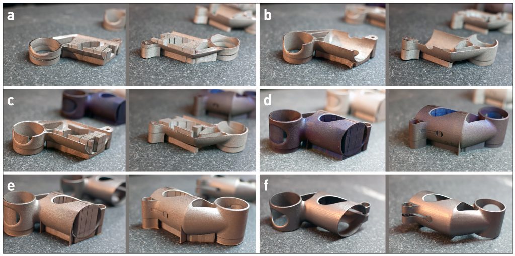
With each iteration, we (and by ‘we’ I mean Dave, whose creativity and enthusiasm for getting the build to work was inspiring) added solid supports in a number of places, chasing built-in stresses around the part with each iteration. The last of these prototypes, although non-functional, was nevertheless a big improvement on the earlier builds — and the process taught us a lot about the idiosyncrasies of my design.
Build 1
In this build, the part is laid on its side and supported only by mesh supports. The build failed at only 15.6 mm in the z-direction, when the recoater jammed on the saddle clamp end of the part, which had lifted from the build platform (Fig. 3a).
Build 2
Here, the seatpost clamp cylinder is firmly fastened to the build plate. But the stresses just concentrated on the other end of the part, pulling the bolt boss and some of the front edge off the platform at a height of 22.7 mm (Fig. 3b).
Build 3
Both ends of the part, the saddle clamp and the bolt boss, are firmly anchored to the build platform. But this created a complex bending moment, pulling the centre of the part upwards; the build failed at 22 mm (Fig. 3c).
Build 4
Here we’ve got solid supports on both the saddle clamp cylinder and the bolt boss, and added an additional solid rib to the middle of the part, tying it down there. This is the first build that completed; all of the others had failed midway through. We’re clearly getting closer, but the bottom of the part has distorted, pulling in and looking like a big “D” (Fig. 3d).

Build 5
To prevent the bottom of the part from distorting like in Build 4, we added a second solid rib. It helped, but only below the centreline of the cylinder; above that, the wall still pulled in (Fig. 3e).
Build 6
Build 6 finally produced a part that’s generally round and complete. This was achieved by extending the lower rib up the side of the part, giving external support to the entire bottom edge of the seatmast clamp cylinder. But although the top and bottom of the seatmast clamp are both basically round, the internal stresses still needed to go somewhere and ended up bulging out the middle of the tube instead (Fig. 3f).
Throughout each of these builds, three things have remained consistent. First, the surface finish on the exterior of the part leaves much to be desired; it will definitely need to be finished in a separate step. Second, the surfaces that needed to be EDM cut from their solid supports (the saddle clamp and the bolt boss) are irregular, and will need to be smoothed into the rest of the part. Third, the internal diameters will almost definitely need to be post-processed by machining or EDM – even the saddle clamp, which overall had passable surface finish, was undersized by .020” – about four times the desired variance.
The net effect is that after six build iterations, each of which took almost two full days to set up, build, stress-relieve and cut off of the build plate, we still didn’t have a functional prototype to test.
Further developments working with Layerwise
As I’ve documented the process and frustrations of developing metal 3D printed parts, I’ve been pleased and surprised at the number of people who have reached out to me to commiserate (if you’re reading this and want to do so yourself, please drop me a line). Without exception, they have expressed solidarity. “We share all of your frustrations,” one person said. “I have been through the same pain as you,” said another.
One of these people was Tom De Bruyne, General Manager at Layerwise. Layerwise is a Belgian company which was started out of the Catholic University of Leuven (one of the premier centres of Additive Manufacturing research); it was acquired by 3D Systems in late 2014. They’re famous for being one of the few service providers who built their own laser metal powder bed fusion machines, and have a ton of experience making 3D printed parts at both prototype and production scale. We struck up a conversation, and soon agreed to work together.
While popular opinion would have you think that quantity is a non-factor with 3D printing, the realities of running a service bureau are much to the contrary. To job shops, quantity is a critical factor; if a part will be produced at large volumes, every detail of its design and manufacturing life cycle must be examined. If, on the other hand, you’re printing a tool or a prototype of a part that will be manufactured conventionally, most shops will focus on getting the first print right without modifying its underlying geometry.
My project falls somewhere in the middle: while my design is certainly imperfect, there are many aspects of it which are very close. Moreover, it poses challenges (most notably its opposing cylinders, oriented 90° apart, and also its thin-wall construction and bolt boss) that will exist throughout any redesign, and solving them now will only improve my ability to deal with them in future iterations.

At the current juncture, the key questions to test were:
- Can we reliably build my current design with minimal post processing?
- Does my current design meet the necessary performance standards (strength, security, etc.) for bicycle seatmast toppers?
In practical terms, the first question boils down to whether we can build a part that can be installed on a bicycle. This means two things: maintaining inner diameters which are round and dimensionally accurate to within +/-.006”, and having a bolt boss on the long cylinder which, when tightened, is capable of securing the part to a bicycle’s seatmast.
I worked with Martijn Vanloffelt, a project engineer at Layerwise, on the next phase of prototypes. He used a few key tricks and built my parts on a machine that Layerwise designed themselves. In order to maintain roundness in the saddle clamp cylinder (the shorter of the two cylinders, which was was going to be oriented more or less parallel to the build plate), Layerwise reinforced the inner diameter with three serrated discs (Fig. 4). They also oriented the part slightly off-axis in both the X and Y axes. This brings me to a point that’s worth highlighting: In metal powder bed fusion, a part’s orientation has a number of effects. First of all, any surface with an angle of less than about 45° (depending on material) must be supported. As a result, it’s generally better to orient a part so that all overhangs are as steep as possible.
But in addition, one must consider the angle between the part and the recoater blade. If the part lifts up at any point during the build, the recoater blade will strike it. The longer the area of contact is, the worse the result will be. Some machine manufacturers offer alternative recoaters to lower this risk (3D Systems ProX uses a roller; EOS offers a carbon fibre brush; Arcam uses a metal comb; and both Concept Laser and SLM offer soft polymer blades), but most use a piece of high speed steel (or, in the case of older EOS machines, a ceramic blade) to spread powder across the build platform. Regardless, it is usually better to orient parts slightly off axis in the XY plane, so that the blade doesn’t contact the part’s walls all at once.
Orienting parts off axis can also help improve surface finish. When a cylinder’s axis is aligned in the XY plane, the top face will exhibit an undesirable stepped appearance; my earlier prototypes all had this feature. When a part is oriented off axis, the surface finish is generally more consistent.
I should note that none of these techniques is guaranteed to work in all cases. Layerwise has a lot of experience building a wide variety of geometries, and has developed a sense of how to anticipate and deal with issues as they come up. I got the impression that the techniques they used on my part are things they’ve used in the past, but each design is different and even a tried-and-true method of dealing with one design isn’t guaranteed to work well on another.
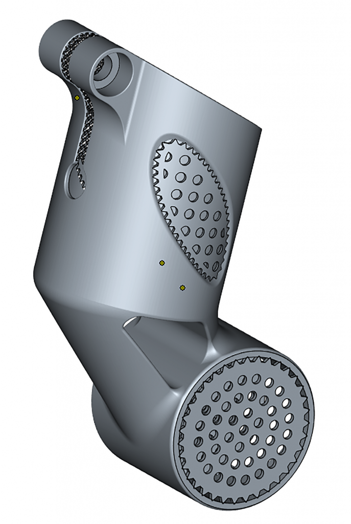
The Layerwise team also put a lot of care into generating mesh supports. Like most of the metal AM industry, Layerwise uses Materialise Magics for their final build prep, and they’ve developed expertise in exploiting the software in creative ways. I’m not able to share a detailed description of the supports Layerwise created for my part, but I can say (and anyone in the industry could confirm) that they were needed in four areas:
- Underneath the part to anchor it to the build plate.
- Inside the saddle clamp cylinder.
- Inside the window in the centre funnel area.
- Inside the seatmast clamp bolt boss.
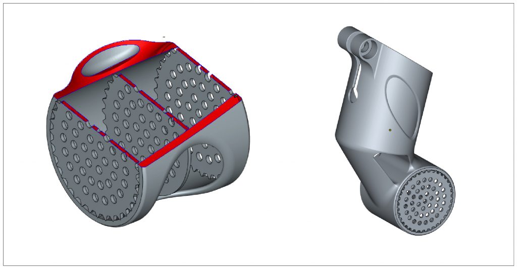
Layerwise took great care to orient the part such that it didn’t require support structures inside the hidden voids in its centre section. This is something that designers and project engineers alike need to think about as a part heads into production. Not only can powder bed fusion not make fully sealed voids (if you printed a sealed sphere, the entire centre would be full of trapped, un-melted powder at the end of the process), but many geometries will require support structures in areas where they’re difficult or impossible to remove. For instance, a Klein bottle could be printed in metal, but no matter how you oriented it, there would likely always be support structures stuck inside its fat end. Because of the angles in my part, it was possible to avoid this, but a different design might not fare as well (Fig. 5).
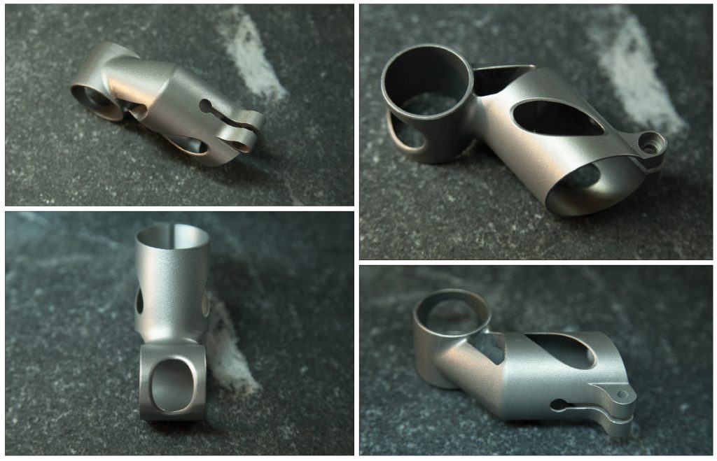
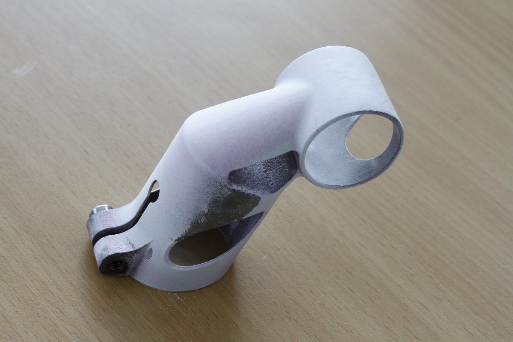
The first part Martijn printed was a big step forward. The build completed successfully without collapsing. However, a new problem arose. The windows on the seatmast clamp area caused the two “leaves” of that cylinder to twist as they were built. By the time the window closed back up, they had become misaligned, and a witness was clearly visible where they joined back together (Fig. 6). The part had a clear flaw and it wouldn’t be acceptable for production.
In the next build, Martijn added a curved, perforated disc to each of the seat mast cylinder’s windows, keeping them aligned as they grew (Fig. 7). The part that resulted was a full success, printing with clean, smooth surfaces and good near net dimensions (Fig. 8).
Considering how much support material needed to be added back into the seatmast clamp area just to get it to build properly, I’m struck again with how inefficient my design is. The windows in the sides of the part are meant to reduce both weight and cost, but a bunch of energy is put into supporting them and then cleaning the temporary supports out again. Instead of windows, I could just as well have replaced the walls with a lattice structure that would both decrease mass and be self-supporting during the build process, bringing the part’s cost down.
This hammers home a point that has plagued my design process: Without knowing and, optimally, having input into how a part is going to be oriented and supported during its build, designers are doomed to creating inefficient designs. Designing for manufacturing requires an intimate knowledge of the manufacturing process, including direct access to detailed information about how the part will be oriented and supported. But in most designer/service provider relationships today, that information comes well after many of the important design decisions have been made, if it comes at all. As a result, it often takes a large investment, both in time and money, just to prove whether Additive Manufacturing can possibly be used to create the part at hand and once that’s been proven, many additional iterations are sure to be needed.
This is a key problem in today’s additive manufacturing supply chain: while parts are usually designed in a solid modelling environment (often Autodesk Inventor or Solidworks, each of which cost between $5–10,000), builds are oriented and supported in Materialise Magics SG+, which costs an additional $15-20,000. As a result, independent designers are stuck with a disjointed process, which requires costly iterations and lots of communication with the service bureau who’s preparing the part to be built.
Regardless, at this point in the process, it didn’t make sense to redesign the seatmast clamp area to reduce supports. Martijn’s build had a very high likelihood of completing successfully, and it was time to put it to the test. It worked!
Post-processing
After printing it, Layerwise did a bunch of post-processing before sending the part to me. This included:
Stress relief
First, the entire build plate was stress relieved. Layerwise’s stress relief process is proprietary, but a typical process [1] would involve putting the build plate in a furnace and bringing it to 600°C over a period of an hour, then holding it there for three hours before turning it off. In theory the furnace is either argon purged or vacuumed, but in practice it may contain small amounts of oxygen too. Layerwise says that the vast majority of the stress relief that they do is performed in a vacuum, but argon is typically used on prototype parts.
Removal from build plate
Then the parts were removed from the build plate. Like most shops I’ve spoken to, Layerwise uses wire EDM, though band saws are also common.
Removal of support structures
At this point, each customer’s part is separated and processed on its own. Supports are removed by a totally unsexy manual process, often involving wrenches, picks, and mallets.
Clean up
Where support structures have been removed additional clean-up is usually necessary. On prototype parts, Layerwise makes extensive use of rotary grinding bits.
Grinding IDs
The inner diameters of my part were both ground to their final size. Layerwise told me that this process was 100% manual, and I was blown away at the precision and consistency of the surface finish.
Shot peening
Any remaining features were micro shot peened with a nonabrasive ceramic medium.
Tap threads
At this point Layerwise sent me the part. Still to be done, however, was to tap the female threads in the seatmast bolt boss.
Herein lies an important point: metal 3D printing does not, in general, produce usable mechanical features like threading. In conventional manufacturing, threading is often just another step on the same machine: mills and lathes can both easily create female threads. But with metal Additive Manufacturing, threading almost always requires secondary processing. As a result, the design files that are loaded into Magics only contain plain-bore through holes; any threading specifications must be documented (and manufactured) separately.
So, the part that I received simply had a 4.2 mm hole in it; it was up to me to cut the M5 female threads. “No problem,” I thought. I’ve got a tap handle right at my desk, and am more than comfortable using it. At this point, I became painfully aware of what’s called alpha case. Alpha case is a very hard, brittle layer of oxygen rich titanium in a part’s surface (an interesting study on alpha case depth is published [2]); it’s the result of the titanium having been processed at high temperatures in environments where oxygen is present. And as I tapped the hole in the first part that Layerwise printed me, I realised that it’s very, very difficult to cut (Fig. 9).
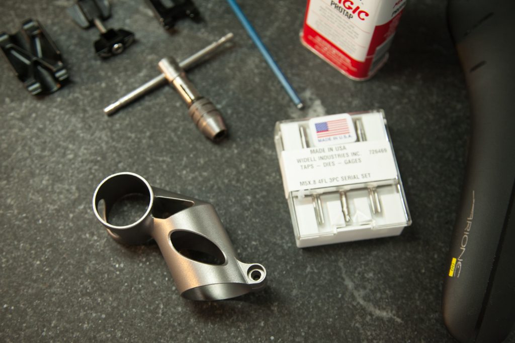
In order to make my job easier, I purchased a set of custom progressive taps from Widell Industries. Progressive taps cut threads in three steps, increasing the thread depth as they go. As a result, the cutting force required is generally much lower. Even using progressive taps, I was shocked at how difficult tapping the second part was. It was incredibly slow going, and produced a lot of heat. I used cutting fluid liberally, and 45 minutes later was done.
I should note here that titanium is a hard metal regardless of how it’s processed. Moreover, alpha case is preventable; in this case, it’s simply the result of the stress relief process being done in a furnace that contains some trace oxygen. Annealed titanium 6/4 has a typical Vickers hardness of about 349 [3], but when a part has been stress relieved in an oxygenated environment, that number might jump to more than 412 [2]. By comparison, 4130 steel and 6061-T6 aluminium, both of which are used extensively in the bicycle industry, have Vickers hardnesses of around 207 [4] and 107 [5], respectively. In future prototypes, I would probably specify that the stress relief should happen in a full vacuum; that would at least make the tapping a bit easier.
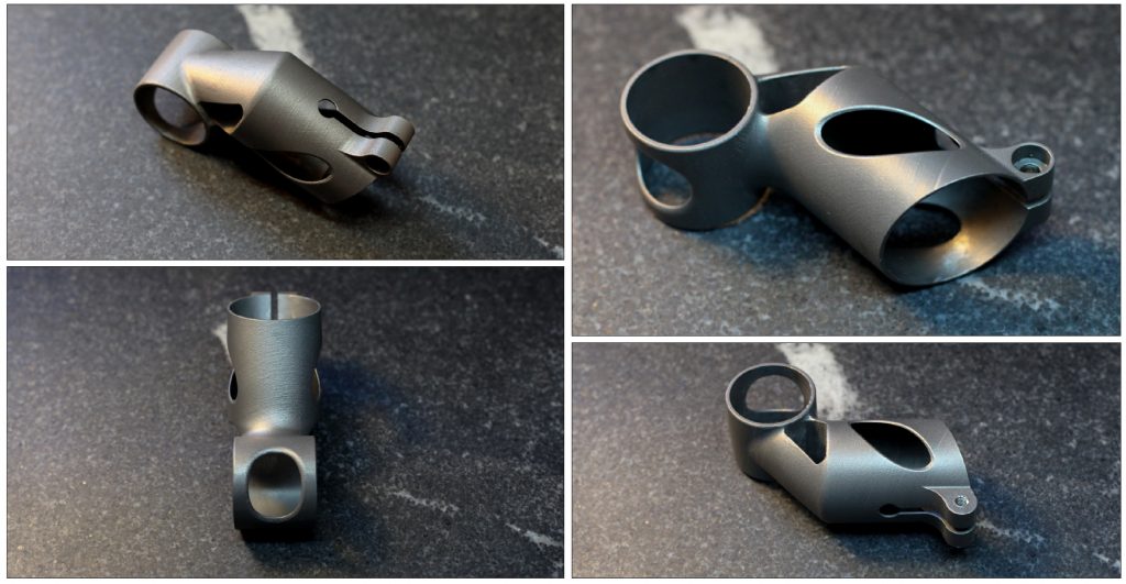
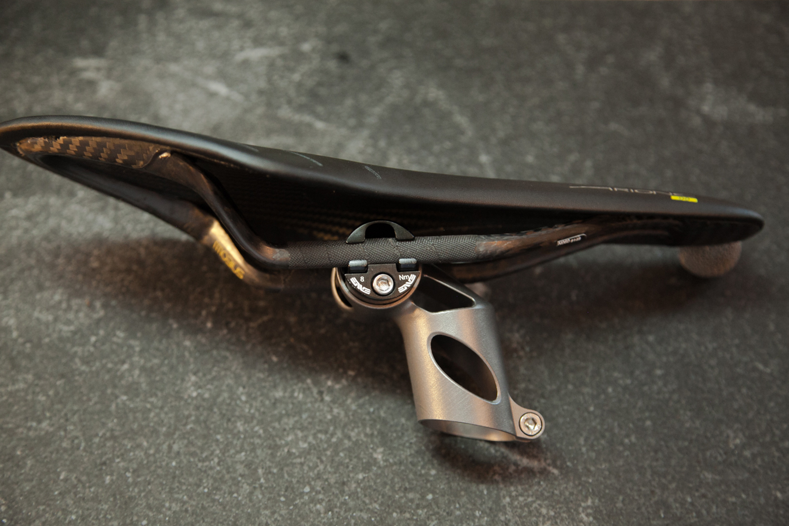
Regardless, the part was finally ready to assemble (Fig. 10). After a total of eight build iterations, I could finally have the part tested — and learn whether my underlying design worked.

Testing at EFBE Prüftechnik
To help understand if my design would handle real world performance requirements, I worked with EFBE Prüftechnik, a German bicycle and component testing facility. EFBE tested the part to ISO 4210–9:2014, 4.5 (Fig. 11). That test entails:
- Clamping the seatmast topper onto a 34.8 mm pillar angled at 73°, and fitting a dummy saddle rail into the saddle clamp.
- Applying 100,000 cycles of a test force of 1230 N, at a distance of 70 mm to the centre of the rail clamp, with the saddle rail tilted down/backwards by 10°.
- Applying a vertical static load of 2050 N to the centre of the saddle rail clamp.
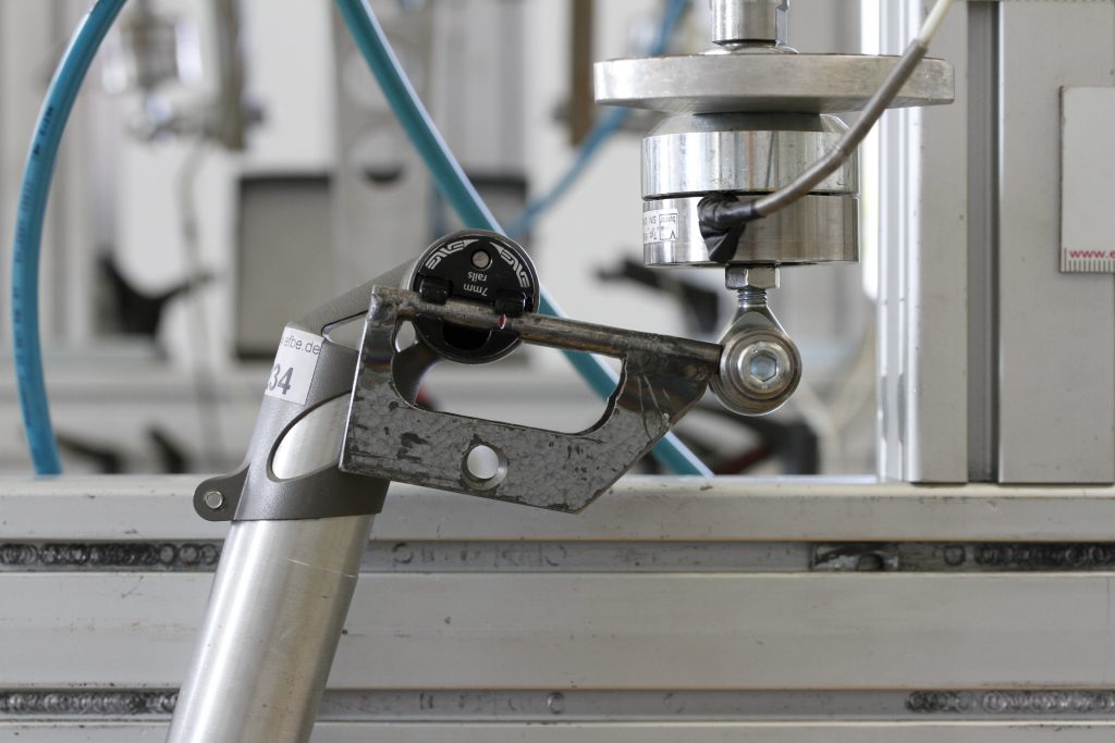
Marcus Schröder, Managing Director of EFBE, put my part through the dynamic test first. It passed.Before he went through the static load test, Marcus asked whether I wanted to make sure I got an intact part back, or if I would rather find the failure mode in the static test. In the latter scenario, he would apply the maximum force his rig could handle and see if he could get the part to break, allowing me to redesign it accordingly. Wanting to know as much about my design as possible, I chose the latter option.
Marcus’s test fixture was capable of applying 3750 Newtons to the part. My part withstood the whole thing. Marcus also used penetrating dye to confirm that the part didn’t have any micro fractures, and it came back negative (Fig.12). The part had met and exceeded the requirements for parts like it.
It’s worth noting that this test is simply that: a test. It’s meant to simulate real world conditions and guarantee that the part meets generally accepted standards. But it simulates those conditions only generally; manufacturers of these kinds of parts will often have their own in-house spec that to tune the characteristics they optimise for. But in general, a designer needs to choose a test, and then optimise his design such that the part fails just beyond the test’s requirements. If I trust the ISO specification implicitly then it stands to reason that I should remove more material from the part; after all, it passed the test with a wide margin.
Regardless, my part could be further optimised. What I’ve done to date was prove a basic concept: That metal powder bed fusion can be used to make thin walled bicycle parts. The question is: Can I make it commercially viable?
Cost
With the current design and an order quantity of ten pieces, the as-printed parts cost about $500 to make. Meanwhile, the most expensive commercially available seatmast topper I’m aware of costs $300, and the fanciest seatpost I’ve ever seen was under $600.
Now, there are a number of interesting things to note here. First, I’m able to buy in fairly low quantities. It’s not unreasonable for me to purchase parts in batches of ten, which is about as low as any non-stock commercial product in the world and much lower than most products that involve forging, casting or CNC machining. If I can sell my part at a high end price point, then it wouldn’t take much cost reduction before I’ve got a reasonable margin, even with a strikingly low order volume. Also, there are a number of ways that I can reduce cost on this part:
- Even keeping the part’s design the same, I can reduce the cost by 25–40% by doubling the layer thickness. This will result in a rougher surface finish, but it’s possible that the difference will be acceptable.
- A significant amount of time and effort can be saved by redesigning the underlying model so that the inner diameters need very little, or even zero, post processing. It’s unclear exactly how much work this will take, but it could reduce the price significantly.
- Moreover, the entire part can be redesigned in order to reduce both the end mass and the amount of support structures necessary. Both of these have a big effect on price, though it will be time consuming to find an optimal design.
All of this assumes that I stick with a laser powered process. Electron Beam Melting, which I’ve been experimenting with in parallel, might reduce cost further.
Electron Beam Melting options explored with Addaero
Last December, when I visited MicroTek in Cincinnati to learn about surface treatments, Tim Bell made a suggestion, “Why not try EBM as well?” Within the US job shop market, Electron Beam Melting is almost an afterthought. While there are many dozens of shops offering (and reselling, I’m sure) DMLS services, only a handful do EBM, and in general they tend to cluster even closer to a single industry.
The closest of these to me is Addaero Manufacturing, which I first contacted in April. Since then, they’ve printed two iterations of prototypes for me. A few observations:
- EBM’s surface finish is, for sure, noticeably rougher. This poses some interesting aesthetic questions (how much do consumers care about having a smooth, shiny part?), but there are practical matters as well. Rough finishes tend to create stress risers, which can result in significantly lower mechanical strength and fatigue life.
- Because the process produces lower thermal gradients during the build, EBM generally results in much lower residual stress in the printed part. This makes the orientation and support structures somewhat easier to deal with.
- EBM allows for parts to be nested in three dimensions, while DMLS parts can only be built one layer deep. As a result, the economies of scale with EBM could be more dramatic.
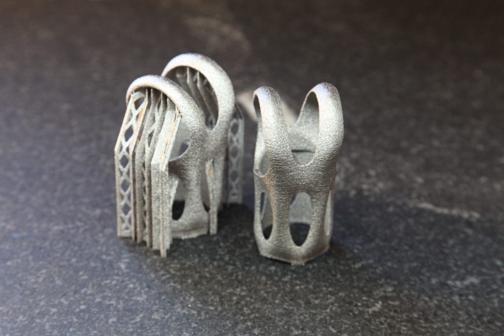
There’s also the matter of part design. As my product has developed, I’ve become increasingly convinced that my part’s design is ill suited for the process. Especially as I move to EBM, there are advantages to designing parts with lightweight lattice structures as opposed to thin walled tubes (Fig. 13). My part is already approaching the limit for minimum wall thicknesses that are possible with DMLS, but EBM requires even coarser features. By thickening some regions and removing others altogether, it’s likely that I can create a part that’s lighter, stronger, and easier to build all at once.
An engineer’s view of the metal AM industry
I didn’t start out with an intense desire to sell 3D printed bike parts. I simply wanted to test the technology and chose the best application I could think of. Neither did I intend in any real way to make a splash in the metal AM industry; I saw myself as an engineer trying to explore a new technology. But, because of the approach that I’ve taken and because of the intelligent, hardworking people that I’ve been lucky to have collaborated with, two surprising developments have come to pass.
The part
The more I learn about the economics of AM, and the more I work to optimise my part for the process, the more I believe that my choice of applications was savvy. My part is far from perfect, but there’s little doubt in my mind that 3D printed titanium bike parts are not just possible to create, indeed I think they will prove to be commercially viable – at least for high end customers and quite possibly at scale as well.
As a result, I’m continuing to develop both the design and the business model that will be required to market, manufacture, and distribute it and other designs like it. This is uncharted territory. Despite extensive research, I’m not aware of any standard commercial products that are made by metal powder bed fusion today, and I’m interested and excited to forge a new path.
The process
But more significantly, I believe that the metal AM industry is doing a poor job of developing new markets and applications for the technology – and I want to change that. Like any industry, metal AM has developed haphazardly. Early on, each player grabbed whatever cards were closest and developed a strategy only after seeing the hand they drew.
But unlike other advances in manufacturing in the past century, AM offers the chance for the product development process to be reinvented. Between the enthusiasm generated by consumer 3D printing and a renewed interest in hardware and logistical problems among young engineers, we have today a unique chance to imagine and execute on a new paradigm in the way that engineered products come to life. However, the most advanced efforts in the field remain behind trade secrets and even where information is shared, it’s often by one-to-one means (like email) as opposed to one-to-many (such as industry blogs), and in static formats (like PDFs) as opposed to flexible and commentable ones (like forums and comment boards).
And so as I develop my own parts, I’m using my product development process as a case study for ways that other teams, in industries much more advanced than cycling, can find ways to work together on shared problems. I believe that there’s a better way for OEMs, machine manufacturers, and job shops alike to develop their products and processes. The technology at hand which promises to be powerful, but is still in the very early stages of true industrialisation and reliability, deserves better than the protective, incremental system that the industry has developed into so far.
In the coming months, I look forward to developing and sharing product development processes, both old and new, with the most forward thinking firms in the industry. If you’re interested in pushing the industry forward in a meaningful way, or are just entering it and looking to learn more, get in touch at pencerw.com/gemba.
Author
Spencer Wright is a designer, manufacturing researcher, and blogger. In addition to building bike parts, he’s currently working on a big new metal AM venture in New York City. You can read more of his work at pencerw.com/gemba
References
[1] Heat Treatment of Titanium Alloy Parts, Standard AMS2801B http://standards.sae.org/ams2801b/
[2] R Gaddam et al, Study of alpha-case depth in Ti-6Al-2Sn-4Zr-2Mo and Ti-6Al-4V, 7th EEIGM International Conference on Advanced Materials Research, IOP Science
[3] Titanium Ti-6Al-4V (Grade 5), Annealed, as published on ASM Aerospace Specification Metals Inc, http://asm.matweb.com/search/SpecificMaterial.asp?bassnum=MTP641
[4] AISI 4130 Steel, normalised at 870°C (1600°F), as published on ASM Aerospace Specification Metals Inc, http://asm.matweb.com/search/SpecificMaterial.asp?bassnum=m4130r
[5] Aluminium 6061-T6; 6061-T651, as published on ASM Aerospace Specification Metals Inc, http://asm.matweb.com/search/SpecificMaterial.asp?bassnum=MA6061t6
LAST MONTH’S MOST-READ ARTICLES


