


Process and quality control for AM: Sigma Labs PrintRite3D® methodology for overall quality assurance
Despite the outstanding promise of metal Additive Manufacturing technologies, inconsistent quality, process reliability and speed are currently holding back industry growth and impacting on the cost-effectiveness of new applications. In the following article Sigma Labs’ Dr Vivek R Dave and Mark J Cola review the technical challenges that are faced in enabling metal AM to reach its full potential and the systems that are currently available to address a number of critical issues. [First published in Metal AM Vol. 2 No. 1, Spring 2016 | 15 minute read | View on Issuu | Download PDF]
Despite the outstanding promise of Additive Manufacturing for critical metal components, three basic limitations exist that will hold back growth and cost-effectiveness of current and future applications; consistent quality, process reliability and productivity or speed. In terms of quality, Additive Manufacturing for critical metal components such as those for aerospace and automotive still exhibits variability between runs, between machines, and over time. In terms of process reliability as determined by part geometry, Additive Manufacturing can only realise a dimensional accuracy of about 100 microns with a positioning accuracy of about 20 microns. Surface finish is also very rough as compared with aerospace requirements. Additionally, the geometry currently has to be measured by expensive post-process inspection methods such as x-ray CT scanning. In terms of productivity and speed, the typical output of an AM machine for metal is still below 20 cm3/hour. The entire world’s production capacity of metal AM machines running 24 hours a day, seven days a week for an entire year would still produce less material than a steel mill could produce in half of one daily shift.
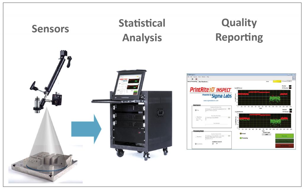
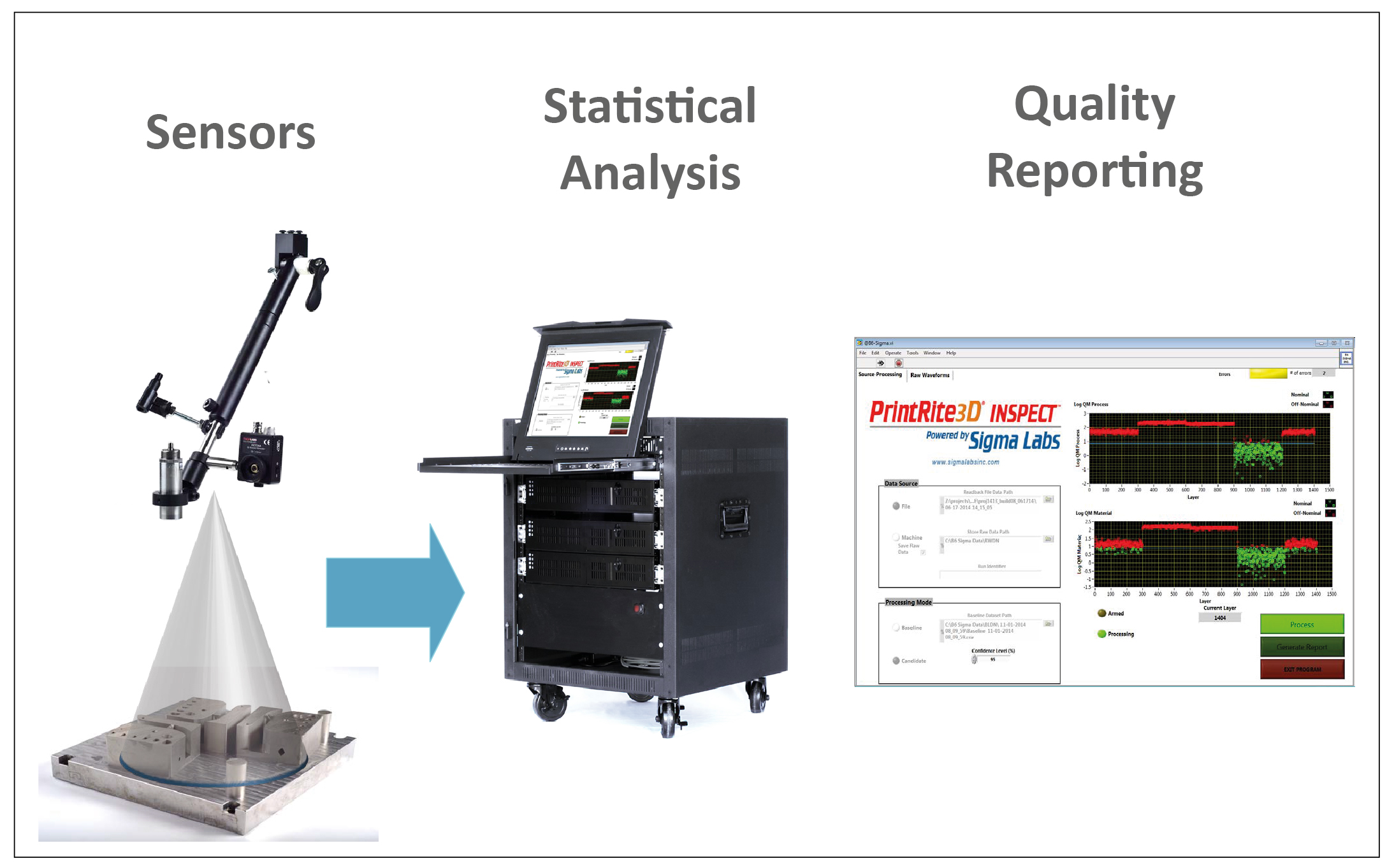
Sigma Labs is addressing the first two issues, namely quality and geometry, with its patented PrintRite3D® Inspect™ and Contour™ in-situ process control, monitoring and inspection software for metal Additive Manufacturing. Specific sensing and measurement technologies will be discussed as well as the Big Data challenges of accumulating what can be terabytes of data per part and then analysing these data to produce actionable knowledge. The software to do this is Sigma Labs’ PrintRite3D® Analytics™. Also, the reporting and interfacing requirements will be discussed to ensure that in-process, real-time on-machine process control and inspection data can be effectively integrated into existing and legacy manufacturing execution systems and enterprise data systems used by many large aerospace, medical and automotive suppliers.

One of the most important barriers to the wider adoption of metal AM is the qualification of AM-produced parts as made evident by the many programs on quality issues of metal AM [1, 2]. The criticality of this has been characterised by many as the single biggest challenge to broader acceptance of metal AM technology [3]. Many manufacturers have openly stated that they see three basic limitations with parts made by metal AM; consistent quality, process reliability and part strength. Until they can be assured of consistency, many manufacturers will remain reticent about AM technology, determining the risks of unpredictable quality too costly a trade-off for any potential gains [4].
From a technical perspective, there are three high-level steps that must be undertaken to design and implement a process control and quality control system for any manufacturing process including Additive Manufacturing. These are:
- The establishment of technical requirements linked to ultimate end-use performance,
- The development and implementation of a process control and quality control system, and associated destructive and non-destructive measurements, capable of directly or indirectly measuring attributes of parts or defects,
- The data analysis, correlation methodology and uncertainty quantification to show, in a mathematically rigorous manner, that the measurements and data gathered by the process and quality control system will in fact correlate with the technical requirements needed to meet end-use environment performance targets, and that the process and quality control system over time will support such objective evidence of compliance.
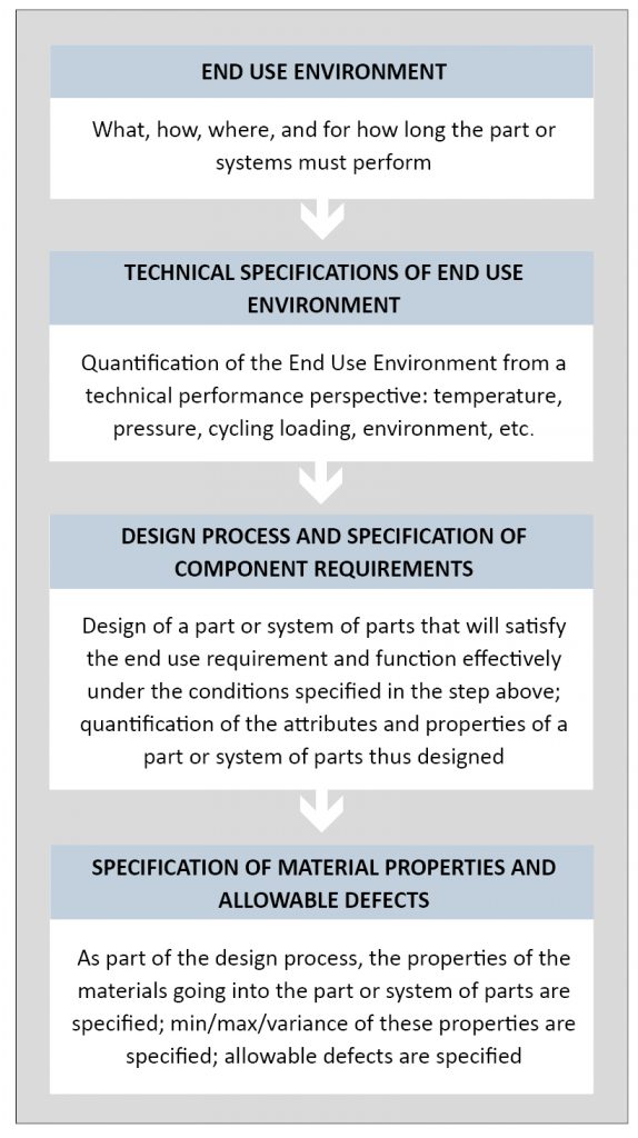
Each one of these high level steps may be further analysed and broken down into subtasks. Fig. 2 shows the steps involved in the establishment of technical requirements as derived from end-use performance targets. This is also the technical requirements list emanating from the part design process. The outputs of this first step are:
- A geometric specification of the part or system of parts, i.e., geometry,
- Materials properties including specifications of min / max / variance / distribution as applicable,
- Other measurable properties or performance characteristics that are unique to the functioning of the part or system of parts (e.g. fluid flow rate in valves or testing of electronic circuits),
- Allowable defects and their attributes in terms of size, shape, distribution, frequency of occurrence, etc.
It is very important to understand the context of the term defect as it is used above. All materials are inherently imperfect. The term refers to lower level flaws, imperfections and irregularities in materials, not defective parts which are allowed to be sent downstream and incorporated into final assemblies. For example, at the atomistic level, lattices of atoms have vacancies where atoms are missing at some sites or interstitial atoms exist at other locations. On the one hand, these may be viewed as material defects, but, on the other hand, the science and technology of physical and mechanical metallurgy is based in no small measure on the creation and manipulation of such atomistic defects.
On a more macro scale, porosity can be considered a defect in powder metallurgical parts, for example. A perfect part without porosity might be possible, but could also be prohibitively expensive. Therefore, based on stress, temperature, fatigue life, etc. the design engineer may specify an allowable defect size, shape, distribution, etc. that will still allow the part to function reliably in its end use environment. So, from the standpoint of creating an acceptable part, these are not part-level defects, but rather allowable limits on material-level flaws and irregularities that will not compromise performance.

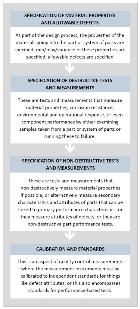
The next high level step in current quality control practice is the design and implementation of a quality control measurement and data collection system. This can be destructive or non-destructive, could involve the measurement of part and defect attributes, or could involve the measurement of part response in a variety of simulated mechanical, environmental or performance tests. There are extensive existing specifications, procedures and standards available for such measurements and therefore the measurement and data collection systems are seldom designed from first principles but rather follow industry standards and norms.
Similarly, there is a vast array of available measurement technology that results in measurements, which can be calibrated to known standards and can also be compared to known independent standards. Fig. 3 outlines in greater detail the steps and considerations that must be taken into account to design and implement such a quality control metrology system.
What is proposed in this article is Sigma Labs’ In-Process Quality Assurance™ (IPQA®) methodology for process and quality control and quality assurance for Additive Manufacturing. The differences between in-process quality assurance and post-process quality assurance are outlined in Table 1.
Application to Additive Manufacturing of in-process quality
In this article we will principally refer to Additive Manufacturing processes in which there is a stationary bed of metallic powder and the heat source (laser or electron beam) scans rapidly over this powder bed so as to melt and consolidate the next layer. The underlying technology is however applicable to other Additive Manufacturing processes and is not limited to powder-bed additive processes.

There are several types of sensor data that could be gathered in such cases but they generally fall into two broad categories. The first sensor type is a sensor that is in the frame of reference of the moving heat source. For example, in a laser-based system, this could be a sensor that utilises back-reflected signals coming from the melt pool to various sensors in the scan head. Such sensors are called Lagrangian as they follow the heat source around the workpiece. The other type of sensor is stationary with respect to the moving heat source and therefore has a potentially broader field of view, or alternatively looks at a specific region in the part being built. This type of sensor is called Eulerian as it is in a stationary reference frame with respect to the moving heat source. Examples of both kinds of sensors could include but are not limited to:
- Pyrometers
- Photodiodes
- Spectrometers
- Imaging sensors such as CCD cameras
- Acoustic emission sensors (usually in Eulerian frame only)
Eulerian and Lagrangian sensors are both useful and they both have advantages as well as disadvantages. These are enumerated in Table 2. It is clear from Table 2 that it would be best to utilise both Eulerian and Lagrangian sensors and to perform a data fusion to arrive at a more accurate representation of the process dynamics of Additive Manufacturing processes. Fig. 4 shows one possible scheme by which this sensor fusion may be effected. Both Eulerian and Lagrangian data are collected. The Eulerian data could include post-process measurements such as microstructural measurements. The Lagrangian data may be additionally processed through various real-time or reduced order models to derive features that are not directly measured in the Lagrangian frame of reference.
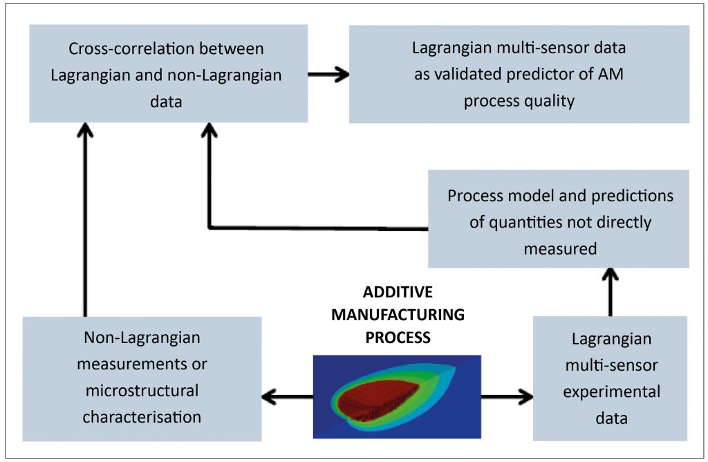
In order to be really useful and produce validated results, the Lagrangian and Eulerian data must be cross-correlated. Then, based on this correlation, features can be assigned as In-Process Quality Metrics™ (IPQM®) which could be predictive of process quality. It is critical to emphasise that in-process measurements of this nature are not directly sensing the presence or absence of defects; rather they are sensing the process conditions under which such process defects are most likely to occur. Fig. 4 therefore offers a template by which in-process, real-time, on-machine data could be used to detect process conditions under which defects may occur. These data could be used for process intervention, i.e., stopping or altering the process before defects occur. Alternatively, if there is access to the real-time operating system governing the Additive Manufacturing process, then such in-process quality data could be used for real-time process control so as to completely avoid process conditions which may lead to defects.

Application to the in-situ measurement of geometry
As discussed earlier in this article, the control and measurement of as-built geometry is critical for metal components, especially those that will be introduced into critical applications such as aerospace or automotive systems. The high temperatures and non-linear thermal gradients in Additive Manufacturing processes contribute to significant thermal stresses which in turn cause distortion and residual stress. Therefore, the control of geometry is a critically important aspect of metal Additive Manufacturing. However, the measurement of merely the outside contour using contact or non-contact means may well be insufficient to fully capture part geometry as additively manufactured articles can have complex internal geometry. Additionally, the currently available methods for full geometric inspection of both internal and external geometry are based on tomographic scanning, such as x-ray tomographic scanning. Such techniques are slow, capital-intensive and involve the use of ionising radiation. Furthermore, as part geometry becomes larger and as the density and atomic number of elemental constituents of a metallic alloy increase, the x-ray energy required to fully penetrate such parts over large geometries becomes quite large indeed. This poses serious technical as well as radiation safety challenges in practice, if x-ray tomographic scanning had to be carried out with gamma rays with energies of several hundred thousand or even several million electron volts. Therefore, an in-situ means of scanning and detecting the as-built geometry is highly desired.
Fig. 5 shows the general process by which geometric data may be collected during an Additive Manufacturing build. There are several critical steps involving calibration, data collection, geometric feature extraction, data aggregation and, finally, rendering and analysis so as to compare the measured point cloud against the original CAD model that embodies the design intent.
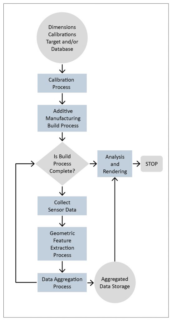
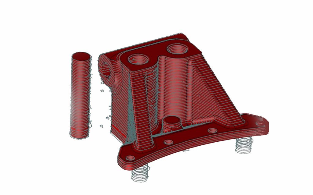
Fig. 6 shows the results of such a process where the part solid model is shown with the various as-built measurement contours superimposed onto the part model itself. In this manner, the manufacturing engineer could quickly make a determination as to whether or not the geometric design intent of the part has been met [6). Additional quantitative analysis can find specific regions which are out of tolerance and can automatically ensure compliance to blueprint / solid model dimensional tolerance requirements.
Big data aspects of process and quality control for Additive Manufacturing
With the advent of IPQA®, the data collection, storage and analysis requirements increase by many orders of magnitude as compared with conventional manufacturing. There is a direct correlation between the information content of a manufacturing process and its flexibility, agility and adaptability to many different materials and geometries. Additive Manufacturing is highly flexible and adaptable and the information content involved in defining part models, translating these to build files, execution of actual builds and, now through IPQA® in-situ, real-time data collection and analysis, is formidable indeed. It is estimated that the total data content of a metal Additive Manufacturing build using full IPQA® for the quality assurance will approach 100-1000 GB per build. If a typical machine performs 125 builds per year, this could translate to 10-100 TB of data per machine per year. It is clear that Additive Manufacturing will quickly overwhelm traditional data handling, storage and analytical tools without the benefit of Big Data Analytics. As with other Big Data solutions, the application to Additive Manufacturing will involve:
- Data compression, data mining and feature extraction,
- Careful consideration of hardware architectures to execute analytics,
- Efficient analytical approaches that would parse smaller subsets, perhaps on massively parallel commercial platforms, and extract meaningful, actionable information.
Just as with any other Big Data application, the central and critical challenge for Additive Manufacturing going forward will be BD2K, or Big Data to Knowledge. What is critically needed is not just Petabytes of raw data, but reduced order, intelligible and actionable process knowledge. This inverse relationship between actionable knowledge and data density is schematically shown in Fig. 7. Here, there are three levels of abstraction and analytics represented. In Step 1, we go from raw time-domain data to feature data. This typically represents a million-fold data compression. Features could be time domain, frequency domain, time-frequency domain, some attribute domain or some other variable domain altogether.
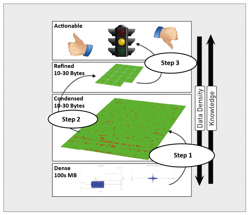
The critical aspect of features is that they preserve essential time domain process physics and are capable of discerning between nominal and off-nominal process conditions, i.e., they have the requisite sensitivity to indicate when potentially defect-causing process conditions occur. At Step 2, various correlations and further analytics are performed on the feature spaces themselves. These additional higher order analytics could take on the form of multivariate statistics, other statistical or non-statistical classification schemes, population of databases, training of expert systems, and various heuristic analyses such as neural networks, etc. The entire purpose of these higher order analytics is to enable pattern recognition and other correlations in the feature spaces. At the highest level of data abstraction, these secondary correlations are now queried and they must be further refined into answers to specific questions, for example, “Has the process drifted so as to be in danger of entering into a set of process conditions that could cause a defect?”
Therefore, in this schematic representation, it is seen that the overall data compression and data reduction as we move from raw data at very high densities to actionable knowledge could be as high a 100 million to one. This kind of a hierarchical approach will be crucial to effectively integrating Additive Manufacturing into an overall manufacturing system together with other processes which will be far less data intensive.
Conclusions
Additive Manufacturing is currently at less than 5% of its eventual market potential according to many analysts [7]. However, several significant challenges and technical problems remain that could prevent Additive Manufacturing from reaching its full potential. Additive Manufacturing has uncertain quality, unpredictable and difficult to measure geometry and rate-limiting speed. While the present work cannot address the manufacturing rate question, the following observations are valuable in guiding the future development of Additive Manufacturing and a rapid qualification approach for part certification.
- PrintRite3D® can be used in addition to, and eventually in lieu of, post-process inspection,
- IPQA® and PrintRite3D® is the only way to establish root causes for failures as it tracks every spatial region over every time step as the part is being made,
- IPQA® using PrintRite3D® is a paradigm shift away from traditional post-process inspection and an enabling method for rapid qualification and part certification,
- Both metallurgical quality and process stability are possible to discern using PrintRite3D®,
- In another aspect of IPQA® using PrintRite3D®, as-built geometry can be directly interrogated without the need for expensive and time-consuming post-process inspection techniques such as x-Ray CAT Scan,
- The use of IPQA® automatically invokes issues relating to Big Data as the sheer amount of information that must be tracked, collected, stored and analysed is many orders of magnitude larger than for conventional manufacturing processes.
What is clear is that IPQA® and related Big Data tools such as PrintRite3D® ANALYTICS™ will be essential to enable the current expansion and future growth of Additive Manufacturing for critical metal components across a wide range of industrial applications.
Authors
Vivek R Dave and Mark J Cola, Sigma Labs, Inc. and R Bruce Madigan, Montana Tech University
Contact
Ron Fisher
Vice President of Business Development, Sigma Labs, Inc.
3900 Paseo del Sol
Santa Fe, NM 87507
USA
Tel: +1 505 438 2576
Email: [email protected]
www.sigmalabsinc.com
References
[1] Wing, I., Gorham, and Sniderman, 2015. “3D opportunity for quality assurance and parts qualification”. Deloitte University Press. A Deloitte series on Additive Manufacturing.
[2] Short, B., 2015. “Quality Metal Additive Manufacturing (QUALITY MADE) Enabling Capability”, www.onr.navy.mil/~/media/Files/Funding-Announcements/Special-Notice/2015/N00014-15-SS-0022.ashx, Quality Made Industry Day, Office of Naval Research July 28.
[3] AlGeddawy T. and ElMaraghy H., 2011. “Product variety management in design and manufacturing: Challenges and strategies,” Enabling Manufacturing Competitiveness and Economic Sustainability, September, pp. 518–523.
[4] US Government Accountability Office report to the chairman, Committee on Science, Space, and Technology, House of Representatives, 2015. 3D printing: Opportunities, challenges, and policy implications of Additive Manufacturing, www.gao.gov/ assets/680/670960.pdf; National Institute of Standards and Technology, “Measurement science for Additive Manufacturing program,” October 1, 2013, www.nist.gov/el/isd/sbm/msam.cfm; both accessed January 4, 2016.
[5] US Government Accountability Office report to the chairman, Committee on Science, Space, and Technology, House of Representatives, 3D printing.
[6] Honeywell Aerospace, www.honeywell.com/ADDITIVE BLOG.
[7] Wohlers Associates, 2015. The Wohlers Report 2015. “3D Printing and Additive Manufacturing State of the Industry”. Annual Worldwide Progress Report
LAST MONTH’S MOST-READ ARTICLES


