


Materialise Magics: Advanced part orientation and support solutions to speed up application development
Materialise NV, headquartered in Leuven, Belgium, has more than 25 years of experience in developing industry-leading software for Additive Manufacturing. The company also operates some of the largest AM factories in Europe, including a metal AM facility in Bremen, Germany. Kirsten Van Praet reveals how the latest release of the company’s Materialise Magics suite can help users achieve higher levels of AM production success through advanced part orientation and support solutions. Key advantages of the metal AM process are also reviewed through a case study and a number of application examples. [First published in Metal AM Vol. 3 No. 1, Spring 2017 | 20 minute read | View on Issuu | Download PDF]
Choosing the right manufacturing technique for a given application usually holds very few secrets and comes naturally to most designers and engineers. For decades, they have had a palette of well-known metal manufacturing methods at their disposal: machining, casting, moulding, welding, extrusion – every single one with its own strengths and weaknesses. Knowing when to choose a growing technology such as metal Additive Manufacturing is far more challenging and raises both questions and uncertainty.
In order to fully benefit from the opportunities presented by Additive Manufacturing, it is therefore necessary to begin with a thorough understanding of the technology, the materials and the design process. A successful metal AM part is always the result of an effective interplay between these factors in relation to the application. Some applications will benefit more from the opportunities than others, resulting in significant improvements in terms of weight, performance, functionality and/or aesthetics.

In general, the main benefits of metal Additive Manufacturing are design freedom, production speed and cost reduction. In conventional manufacturing, a product’s functionalities and appearance are a direct consequence of the manufacturing process of choice. Additive Manufacturing, however, by means of its layer-wise production, suffers from almost no manufacturing boundaries, especially in terms of geometrical freedom. This results in new and exciting opportunities for product design.
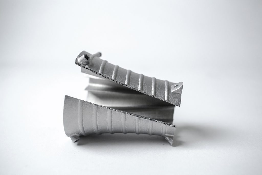
The volume-based cost calculation of a part, as opposed to a complexity-based one, motivates designers and engineers to actively and economically explore more complex shapes, working towards an optimal functional design (Fig. 2).
Unlike conventional production methods, Additive Manufacturing requires no additional tooling during the production process. As a result, start-up time and costs are limited and independent of the batch size or the number of design variations of one part. This means stock levels can be kept low and necessary design changes can be implemented quickly. This speeds up and optimises the product development cycle and opens doors for customisation and on-demand production. It also allows a reduction in terms of components of the part, which means some assembly steps, such as welding or bolting, are no longer needed. This may also offer additional advantages in relation to component integrity and lifetime.
How software can contribute to process stability
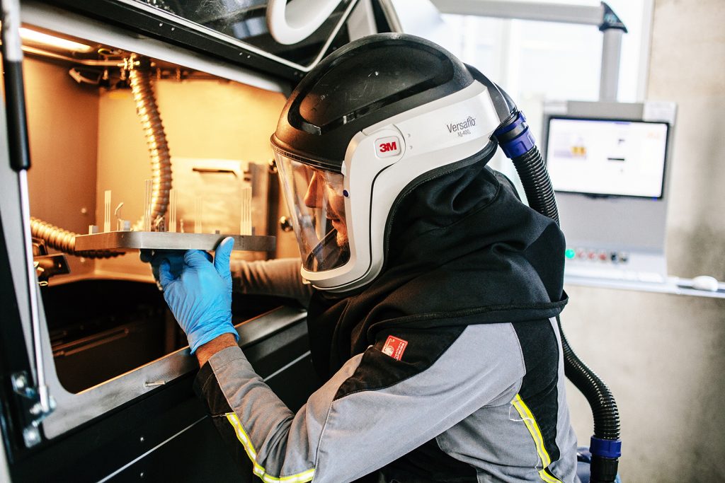
The Additive Manufacturing of metal parts can be challenging. Today’s market defines the initial learning curve as a two-year period characterised by trial and error experiments, build crashes, vapourised money and time, all mixed in with the occasional correct build. A thorough understanding of how the metal Additive Manufacturing process works is therefore essential.
Whilst it is critical to understand and consider the whole manufacturing process, from powder characteristics to design guidelines and process parameters, including post-processing steps, some of the main stumbling blocks linked to metal Additive Manufacturing are thermal stresses, deformation and shrinkage. How a design engineer positions a part and generates support structures has a huge influence on the success of a build.

Software therefore plays a key role in the metal Additive Manufacturing process. Materialise’s Magics software, core of the company’s flexible software suite, is based on an in-depth understanding of the mechanisms behind metal AM, guiding the user on the issues such as best part orientation and support generation. A number of advanced build validation tools analyse the build risks of a part and its support structures to help detect and avoid issues.
Part orientation
A good part orientation is the first step to a successful build, barring warping or a premature termination of the build process. Users can prevent warping by limiting the surface area of each layer and thereby controlling heat build-up. Large differences in temperature between two consecutive layers compromise build quality and can lead to build crashes, so users need a tool that allows them to analyse the surface area for each layer along with the heat distribution within a build.
One of the new tools in Materialise Magics21 is the slice distribution graph tailored for metal applications, which gives users total control of the build process (Fig. 3). With the slice distribution graph, users can quickly visualise the surface area per slice to improve part and build quality. This can be done for one or more selected parts or for the entire build platform. The tool also takes into account support structures.
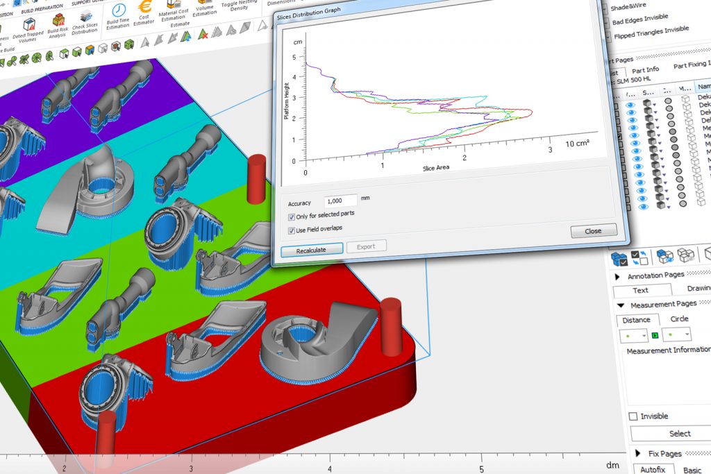
For metal Additive Manufacturing production machinery that is equipped with more than one laser, a multi-optics option ensures an evenly distributed workload. Users can adjust the orientation of parts or position them in different areas of the build platform and all data can be exported to Excel for a more detailed analysis of the results, helping to achieve an optimal part orientation.
The Magics orientation tools help users orient parts intelligently. This can lead to a reduction of support structures, decreasing material usage and reducing post-processing work. With the Orientation Optimizer tool, for example, users can mark the zones of the part where they do not want to have any support structures. They are then guided to an orientation in which the zones are self-supporting. The Automatic Placement tool makes it easier to position parts by doing some of the work for you.

Depending on the user’s goal, optimal orientation could consist of the right balance between the reduced surface area per layer and the amount of support needed. The support preview tool gives users a preview of how the support structures might look once generated. The preview is updated in real time during the orientation, cutting down the number of orientation iterations.
Support generation and function
In metal Additive Manufacturing, support structures fulfil a greater purpose than simply supporting a part during the build process.
Optimal support generation minimises deformation, prevents build crashes and reduces post-processing work.
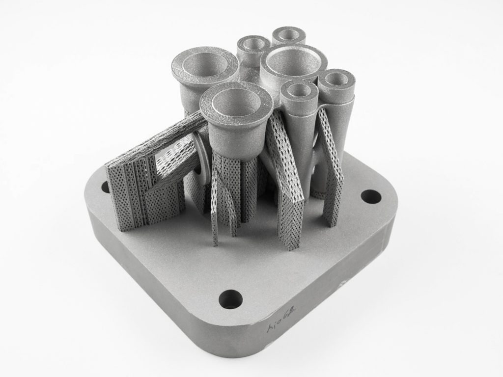
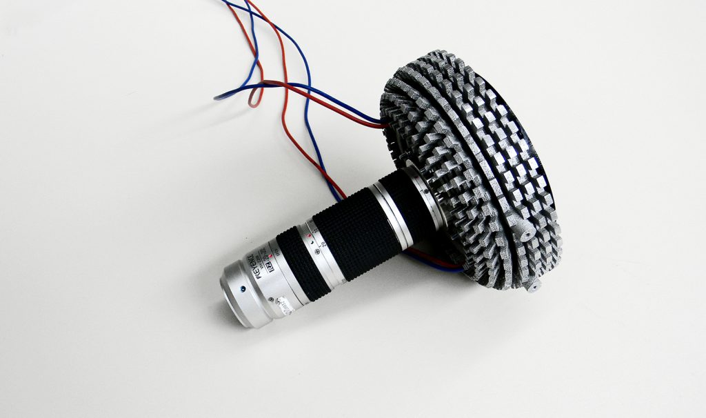
There is a wide range of support types, each with its own unique benefits. Depending on the geometry of your part, a specific selection will lead to the best results. For instance, cones and tree supports are particularly interesting for small, thin parts and jewellery (Fig. 4). Materialise Magics provides support structures within a semi-automatic process. Users can set custom parameter profiles and easily tweak them afterwards when needed. They can also create their own support structures in CAD and then import them into Materialise Magics.
Manage heat and avoid deformation
To more effectively conduct the heat from the part to the build platform, Magics allows the use of volumetric support elements. These elements also make sure deformation is avoided by anchoring the part firmly to the build plate. With the software library, users can thicken specific supports as well as choose between solid volume, blocks, cones, tree support structures and more.
Block support structures look like a grid of lines, with each line normally assuming the thickness of the melt pool. With a new feature in Magics21, you can thicken the borders of the grid to conduct the heat more effectively and avoid warping.
Strategies for improving part stability
A powder-bed machine’s recoater system can have a significant impact on the part and its support structure during the build process, which might result in the part shifting. In addition, a deformed part’s edges may protrude over the powder bed, which can potentially lead to a collision that could damage the part and/or the recoater mechanism. A strong connection to the platform is therefore imperative.

With the rescaled platform projection area tool, users can expand support structures and strengthen the connection with the platform. The teeth size, shape, penetration level and other parameters also influence the strength of the support structures. For instance, a cylindrical platform connection can reduce build failures by offering a stronger connection to the build platform.
Saving material with patented hybrid support structures
A brand-new type of support in Magics21 is the patented hybrid support structure. This support structure is particularly useful when a certain height from the build plate is needed. It consists of three different parts: the upper part is block support, the middle part is volume support and the lower part consists of tree or cone support structures (Fig. 5).
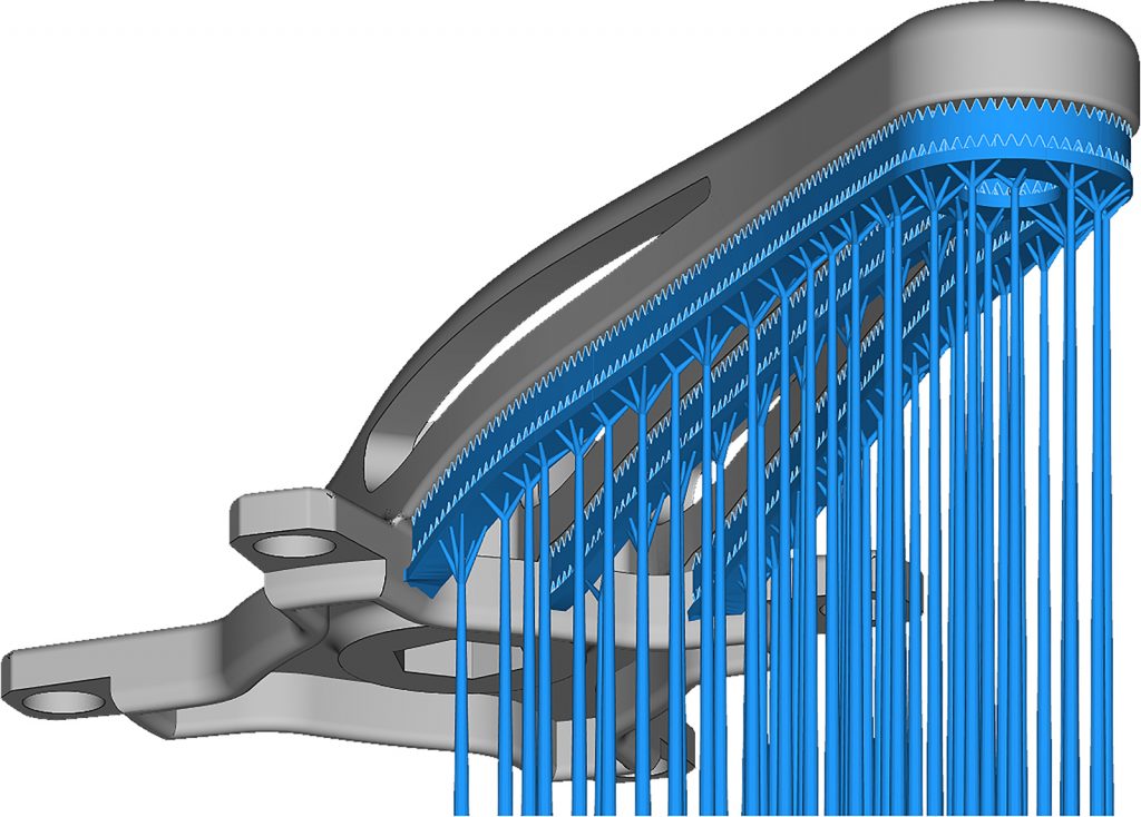
Metal support structures have to fulfil somewhat conflicting requirements. On the one hand, they need to counteract the stresses generated in the metal AM process and hold the part in place, whilst, on the other hand, they remove the heat generated by the process as excess local temperatures may lead to poor surface quality and/or poor mechanical properties.
To hold the part in place and counteract stress, a user would ideally use bulky, volume-type support structures (trees/cones/solid STLs) placed in well-chosen positions. Such support structures are strong, quite easy to remove, fast to scan and do not trap powder inside. To achieve parts with good surface quality, however, it is crucial that abundant contact points with the part are present, as for example with block supports. This ensures proper, local heat conduction, avoids dross formation and yields good surface quality.
Hybrid support structures allow users to benefit from the best of both worlds. At the top, there are block support structures to obtain the surface quality that is required; at the bottom, far away from the functional part, there are solid support types (trees/cones) that are fast to manufacture, consist typically of less material (smaller total volume) and do not trap unmelted powder within them. Choosing cones offers more stability, whereas tree support structures really limit powder usage. The middle plate ensures good heat transferal from the block support to the tree/cone support structures.
Users can tweak the parameters of the block support structures: they can adjust the thickness, make the teeth larger or smaller and perforate the structure or fragment it. Users can also select a specific hatching style. Next, they can choose the thickness of the middle plate. Finally, the user can tweak the tree or cone support structures. The distance between the cones/trees can also be controlled and their thicknesses adjusted. When using tree supports, users can also select the number of branches per trunk.
A great advantage of hybrid support structures is that the placement is fully automatic, saving a significant amount of time. If a user had to generate such a combination of support types themselves, it would take hours if not days. In addition, this type of support reduces the scanning time as well as the effective volume of the printed support structures. Hybrid support structures therefore lead to improved surface quality, reduced material usage and a reduced process time.
Support removal considerations
In cases where support structures have to be removed manually, easy support removal and smart support placement technology can significantly reduce finishing time.
Smart support placement
If support structures normally touch a part in two different areas, for instance inside a tube, users can work with angled support structures. With these structures, a user can manually guide the support structures from their part to the build platform, avoiding unnecessary contact points (Fig. 6). If the connection with an area of a part cannot be avoided, the user can guide the support structures to an area that is easier to process such as a flat surface rather than a curved one. With the rescaled platform projection tool, users can also downsize the width of support structures to limit the area that requires post-processing.
Easy support removal
Solid support structures can be combined with fine teeth that are strong but easy to remove, or they can select predefined break-off points. The latter have the form of an hour glass and will break off in the middle. This avoids the pitting that can result from poor support removal and damaging the part. The user can then smoothen the surface. Fragmented block supports or a clearance between the support structures also facilitate support removal.
Another way to remove support structures without compromising surface quality is by adding some additional material at the places that need the support structures. These can then be milled to obtain the intended final shape, a feature in Magics21 called milling offset.
Recuperating valuable powder
As AM grade metal powder can be very expensive it is preferable to recycle as much of the powder as possible. For safety and contamination reasons it is also best to remove as much powder as possible in a controlled atmosphere before removing the support. With perforations and fragmentations of surface support, Magics can ensure the recuperation of powder while preserving the strength of supports. Designers can also hollow solid supports or place a structure inside them to reduce build time.
Optimal machine parameters save time and reduce component stress
In addition to data preparation software, machine communication software also influences the quality and success of metal additively manufactured parts. With the Materialise Build Processor users can divide parts into a hull and a core, with each being built with a different scanning strategy. Build Processors can also assign different scanning strategies to different types of support structures. For instance, support structures can be scanned every two layers, speeding up the scanning process and reducing stress.
With Materialise’s Build Processor, Control Platform and Inspector software, the user can fully control the metal Additive Manufacturing process. They can inspect the build process strategy, monitor and log data in real time and save valuable time and material with a root cause analysis of failed builds. The goal is predicting and detecting errors with less effort and increasing overall confidence in the quality of the finished metal parts.
Case study: Design and manufacture of a spider bracket
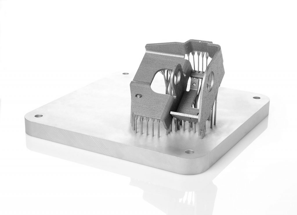
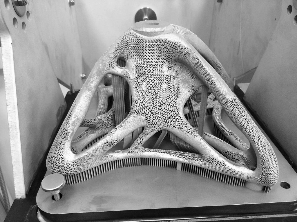
This case study highlights how a topology-optimised metal spider bracket was successfully developed and manufactured (Fig. 8). Together, design enhancement software, data preparation software and machine communication software lead to an impressive titanium AM part.
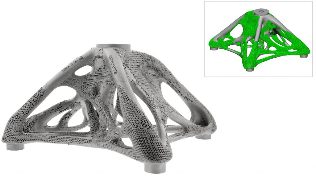
Materialise worked together with Altair and Renishaw to create this component. The original design was based on brackets that connect the corners of architectural glass panels used in atria and floor-to-ceiling wall glazing. The bracket contains a hybrid lattice structure that could not have been created with conventional manufacturing methods. The success of the finished part is due to the application of Altair’s lattice-based optimisation software, Materialise’s Magics, 3-matic and Build Processor software and the advanced capabilities of Renishaw’s metal AM system.
The spider bracket’s design mimics the biological structures that can be found in nature. Altair’s topology optimisation software created a unique, organic shape that is both light and strong (Fig. 8 inset). The lattice structures also provide enhanced stability and improved thermal behaviour. However, topology-optimised models need sufficient smoothing prior to final manufacturing.
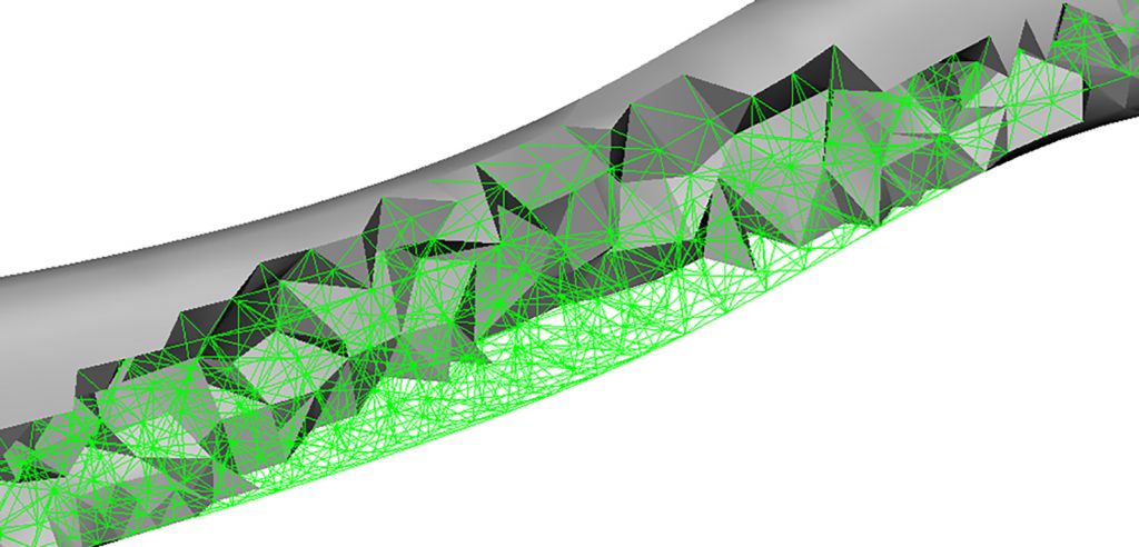
Topology optimisation resulted in solid regions and regions with a lattice structure. The irregular interface between the lattice and the solid mesh makes Additive Manufacturing difficult and can lead to stress accumulations. This means that the edgy geometry needed reconstruction. It was here that Materialise’s 3-matic design optimisation software for Additive Manufacturing was used and the design engineers at Materialise easily transformed the rough data (Fig. 9) into a clean model with smooth surfaces (Fig. 10).
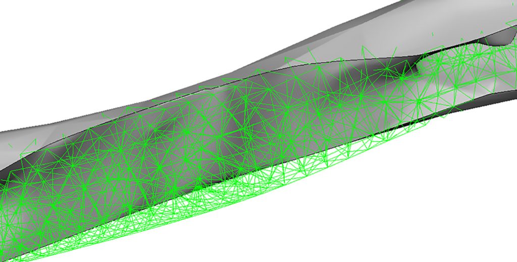
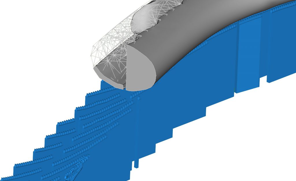
Besides the irregular geometry, the support structures attached to the lattice could potentially cause problems during the laser melting process. For instance, when the supports are removed, there is a risk that some of the lattice structure could break off as well. To prevent this issue, Materialise engineers placed a thin layer of solid material under the lattice structures that needed support (Fig. 11). In certain regions, the design was also enhanced with Materialise 3-matic to reduce the numbers of support structures necessary.
After these design enhancements, engineers used Materialise Magics to add the logos of the three companies, find the optimal orientation, position the part within the build envelope and generate support structures. Normally such a large and complex data set would be difficult to process and manipulate. In this case, the calculation of the structures was postponed until the slicing step. The slice-based technology of the Renishaw Build Processor, powered by Materialise, applied the 3D geometry of the spider bracket at the slice level instead of at the STL level, which kept the file size remarkably low.
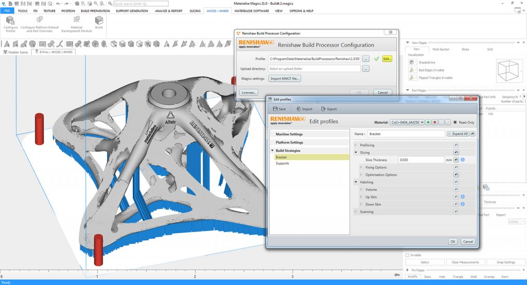
The build file was therefore sliced and tested according to the material parameters assigned by Renishaw (Fig. 12). After this, the model was turned into a titanium part thanks to the expertise and technology developed by Renishaw.
The striking bracket was built successfully, translating almost 4 GB of data. The never-seen-before design and unique mix of solutions that were used provide an insight to the new era of shapes and products to come in metal Additive Manufacturing.
Markets for metal AM: key application examples
Heat Sinks
Heat exchangers are designed to dissipate heat, for example the heat generated by electronic and mechanical devices (Fig. 14). The surface area highly influences the performance of the heat sink, but typically the available space is rather limited. That means maximising the surface area within the dimensional boundaries is the key challenge.
The design freedom offered by Additive Manufacturing allows for the creation of thin, complex geometries and lattice structures that make optimal use of the available space. Combined with the excellent thermal conductivity of additively manufactured aluminium, heat sinks are an especially well-suited application.
Spare parts
The demand for spare parts is typically intermittent and it is difficult to forecast when specific parts will be needed and where. Keeping those parts available on the shelves is a costly operation, requiring storage for the parts and the retention of tools. Additive Manufacturing allows for on-demand and local production of spare parts, avoiding inventories and transforming entire supply chains.
To fully profit from the technology in terms of material usage, weight and functionality, a redesign is recommended, but, as more companies adopt Additive Manufacturing for initial production, the management of spare parts will become simpler.
Structural components
The fields of bionics and structural optimisation show a great potential for industrial applications. Structures generated as a result of topology optimisation often lead to highly complex shapes. By making use of the geometrical freedom that Additive Manufacturing offers, these shapes can be realised with fewer manufacturing-related restrictions or adaptations. Given the excellent mechanical properties of additively manufactured metal parts, this results in structural components that reduce the overall weight and material waste without compromising strength. This approach offers significant possibilities in the design of structural components.
Tooling components
In the tooling industry the pressure on costs is high. Controlling those costs can be done partly by optimising the part throughput of the machine and partly by reducing waste. One solution is the use of conformal cooling. By making tools through Additive Manufacturing, highly complex internal cooling channels can be integrated close to a part’s surface. This results in an optimised heat flow and time gains during cool down, reducing the risk of warpage, improving part quality and shortening the production cycle of parts.
For parts that are so complex that conventional manufacturing methods would require labour-intensive and costly tools, direct production in Additive Manufacturing can be beneficial.
Medical devices
Mass customisation can be implemented sustainably only through Additive Manufacturing, where design flexibility does not compromise cost-effectiveness. For this reason, the medical industry was one of the earliest adopters of Additive Manufacturing to make custom parts such as implants and personalised medical devices (Fig. 15).
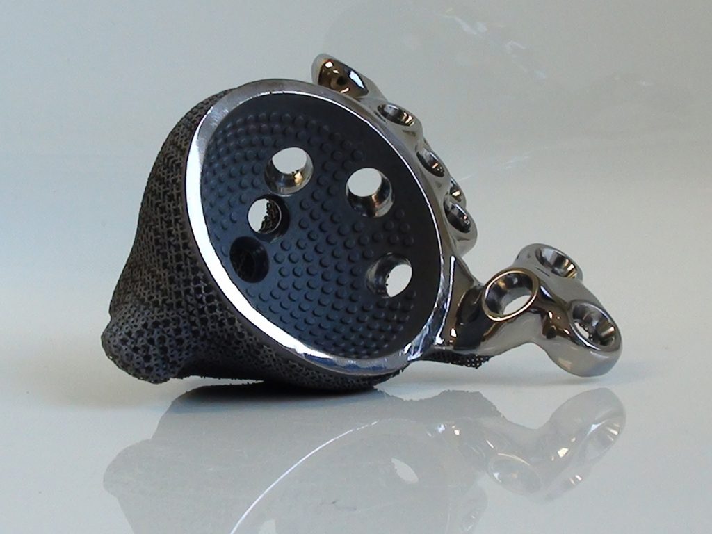
The biocompatibility of AM titanium, combined with the ability to create complex structures, has opened new opportunities to minimise surgical impact, stimulate bone ingrowth and improve a patient’s mobility. At that level of patient-specific customisation, Additive Manufacturing is the only technically feasible and cost-effective production method.
Food processing
Food processing companies are often in need of custom-made parts. Making tools for these small series often raises production costs. The manufacturing cost of Additive Manufacturing, which is not dependent on series volume, offers ways to keep costs down.
Additionally, the biocompatible nature of AM titanium allows for direct contact with foods and liquids. Combined with the design flexibility, this gives room for more functional and complex components used in gripping, feeding and depositing food products. By integrating functionality, the number of components can be kept lower, reducing the risk of downtime and the need for maintenance.
Fashion and design
Attracted by the ability to design exceptional shapes and geometries, for both aesthetics and functionality, designers and artists have been experimenting with Additive Manufacturing since the early days of the technology. With metal Additive Manufacturing becoming more accessible, doors opened to create things that were previously unthinkable. Personalised jewellery, eyewear, design objects and accessories can be made in an ever-growing range of materials and finishes. In a sector where brands require rapid design upgrades to maintain market competitiveness, Additive Manufacturing is a rewarding choice owing to profitable low-volume production runs and fast lead times.
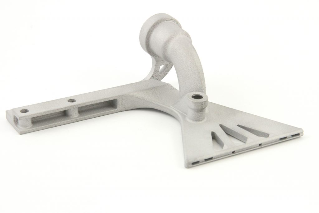
Industrial automation
Every project in industrial automation comes with its own requirements, calling for a custom solution. Additive Manufacturing addresses this challenge through cost-effective production of small series and unrestricted design possibilities. Complex integrated functionality allows grippers and clamping devices to use fewer components and less manual assembly. In the component shown in Fig. 16, volume optimisation results in a lightweight and inexpensive gripper that allows robots to work at optimal speed. The high strength and low weight of AM aluminium makes it a good fit for durable customised automation solutions, while stainless steel can be used for food-safe applications.
Conclusion
What is clear from these application examples is that all sectors of industry are now starting to recognise the opportunities that are presented by Additive Manufacturing. One of the most significant challenges facing those who are looking to move into component production is how to reduce the steep learning curve associated with a process that is so radically different to conventional technologies. It is important that new entrants to this field recognise that software is a key additional consideration when starting out on the AM journey – this article just touches on two aspects of what specialist software for AM can offer.
The requirement to start with an AM machine is obvious, as is the need for appropriate materials, but all too often the advantages that software solutions can bring – and the impact that they can have on reducing speed to market – are realised very late in the day.
Contact
Materialise NV
Technologielaan 15
3001 Leuven
Belgium
Tel: +32 16 39 66 66
[email protected]
www.materialise.com
All images courtesy of Materialise
LAST MONTH’S MOST-READ ARTICLES


