Inspect Additive Manufacturing, stop monitoring: Phase3D’s unit-based, in-process inspection solution for powder bed AM
AM is at a pivotal stage, evolving from a prototyping tool to a scalable manufacturing solution. This transition necessitates real-time, process-specific inspection to ensure consistent part quality. Phase3D is meeting this need with real-time inspection solutions specifically for powder-bed processes. Its technology enables manufacturers to inspect each layer during production, enhancing product development, optimising parameters, and improving process control for end-use production. Here, Niall O’Dowd and Noah Mostow dive into the specific applications of the company's Fringe Inspection technology. [First published in Metal AM Vol. 10 No. 3, Autumn 2024 | 15 minute read | View on Issuu | Download PDF]

About Fringe Inspection
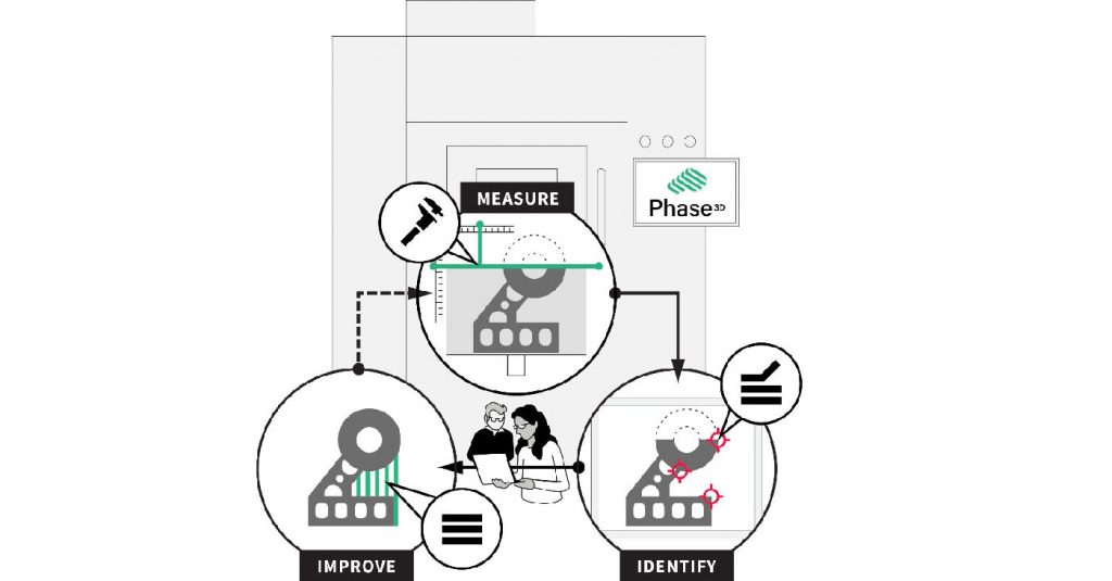
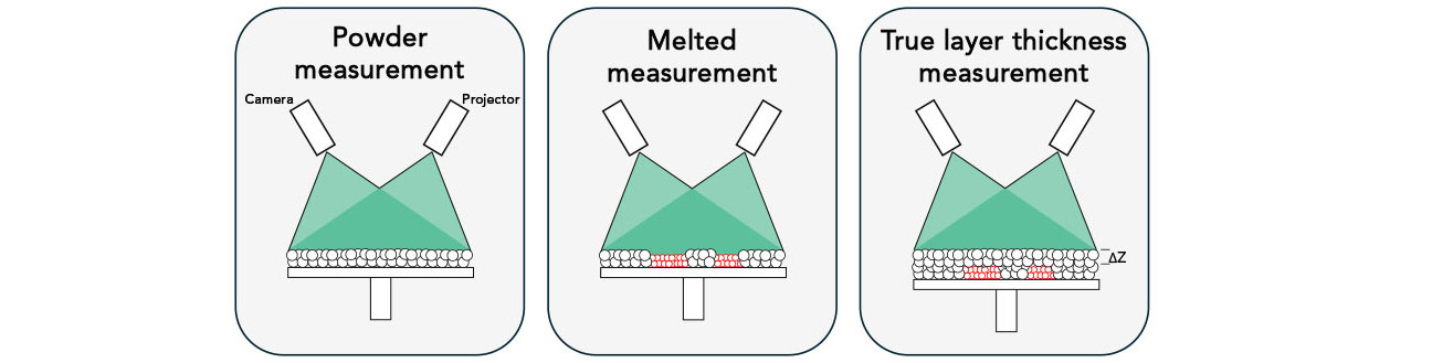
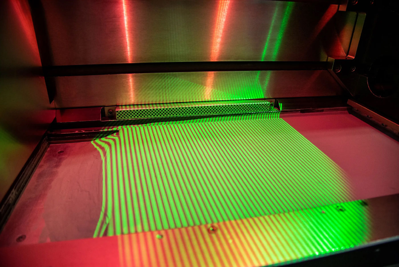
Fringe Inspection is a hardware and software product that uses structured light inspection to measure the Additive Manufacturing process and identify anomalies (Fig. 2). These anomalies can be correlated to critical part flaws so users can improve their build quality and repeatability. Fringe Inspection works by projecting patterns of light onto the part during the build and using a camera to capture variations in light intensity, allowing for the measurement of the 3D profile of every layer in the AM process, capturing three measurements per layer (Fig. 3). As of autumn 2024, the patented [1] solution is available for PBF-LB, Binder Jetting, and Cold Spray AM. This article will primarily focus on PBF-LB applications.
The result or output of the three scans, as shown in Fig. 3, is a point cloud, or 3D profile, of:
- The uniformity of the powder spread across the build area
- The uniformity of the melted part area
- The amount of powder spread across the build area, including previously melted areas
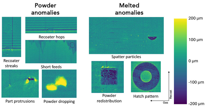
By analysing these three measurements, Fringe Inspection automatically identifies and reports powder layer anomalies such as short feeds, hops, streaks, part protrusions or powder dropping (Fig. 4). Melted anomalies such as powder redistribution, spatter, or hatch pattern variations can also be detected. Users of Fringe Inspection include NASA, the US Air Force, NIST, and several major aerospace OEMs, who utilise it to detect anomalies and gain objective inspection-level insights into their build quality.
Fringe Operator and Fringe Qualification
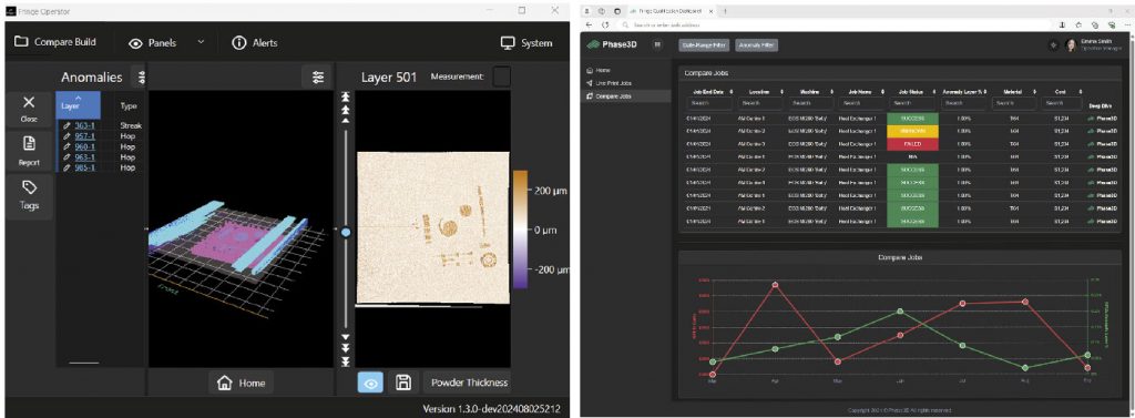
To make the measurement and anomaly detection data useful on the shop floor, the Fringe Inspection system includes visualisation and quality assurance tools: Fringe Operator and Fringe Qualification, respectively. Fringe Operator includes anomaly detection and deep-dive analytics features so users can understand the build performance as a whole or by every layer’s features down to the micron level. Fringe Qualification works alongside Fringe Operator to provide high-level details of build quality across customers’ fleet of AM machines. It provides users with an executive-level build report as well as a dashboard to oversee all the builds on site and allow for comparison and process control (Fig. 5).
End-use customers use Fringe Inspection from early-stage development to final production, including product development, parameter development, and process control. Each application supports users in reducing project lead time, increasing machine utilisation, and ensuring build quality.

Product development with Fringe Inspection
Companies use Additive Manufacturing in order to develop new products. The technology may be used to replace already existing parts with a new metal AM part, to create entirely new parts, or to bridge the manufacturing timeline while tooling is being produced. The opportunities are endless, but getting a part to build correctly on a first, second, or even third try can be a challenge as designers and engineers push the boundaries of what is possible.
For example, a designer may want to use as few support structures as possible or design thinner-walled structures supporting thicker features. However, both can lead to thermal deformation of the part during the build process, causing the part to warp and protrude above the powder surface, impacting the recoater blade and parts or geometries downstream. Even though these design features reduce post-processing or enhance part performance, they can cause serious problems during the build.
With Fringe Inspection, parts warping during the process and protruding from the build surface are easily identified. Users can easily run a root-cause analysis of design problems during the first build of a part, drastically expediting the design process. Historically, root cause analysis of part failures included many unclear steps, but the software allows users to see the problems in real-time and make changes faster. For parts that self-repair during the build, Fringe Inspection is critical to understand variation and abnormalities of internal features (Fig. 6).
Even after a successful build, quality systems must be established to ensure that future builds will be of the same quality. Fringe Inspection provides customers that are developing new products with an objective inspection technology that identifies when and where a part has failed, enabling them to control the process from the first build to thousands after.
Fringe Inspection for parameter development
Every company has its proprietary build parameters for Additive Manufacturing. Even though machine manufacturers supply standard parameters for many materials, end users are looking to push the bounds of what the machines can do while getting the best performance from the parts. This means many AM users are investing tens to hundreds of thousands of dollars to develop the parameters for the parts and geometries they want to manufacture.

Developing optimal parameter sets can include extensive part testing, including testing density cubes, serial sectioning, or other mechanical testing. The problem is that many parts that are produced during the parameter development process experience extensive build anomalies. These historically are not identified, and the root cause analysis of defective parts is invalid due to a lack of in-situ inspection data.
With Fringe Inspection, customers measure the build in real-time and identify anomalies that impact the part’s performance. By cancelling the poor-performing parts, customers are saving time and money by not putting these parts through ex-situ inspection.
Even more importantly, during this critical phase of development, customers are able to understand the root cause of part or geometry failures, which may not be impacted by the parameters themselves. In the build shown in Fig. 7, a recoater streak was persistent during the entire build, repeating on every layer. Further analysis showed the recoater itself was damaged, rather than the parameters causing the issue. Not surprisingly, after CT scanning the parts impacted by the recoater streak, a higher level of porosity was identified in that region (Fig. 7).
Without Fringe Inspection, users would be unaware of the recoater defect, as the streak was not visible in the visual images, meaning that these parameter sets would have failed during post-inspection, even though the results do not accurately reflect the performance of the parameters.
By measuring the entire build process – including true layer thickness measurements – users can now quantify how much powder was spread across the entire layer. As the AM industry seeks to build parts faster, thicker layers become extremely valuable. The technology can also be used to test thicker layers and understand their impact on a part’s performance as well as the impact of thick layers on different geometries. In the future, instead of multiple builds to finalise new parameters for different materials or performance requirements, users will be able to gather all the data necessary to qualify a parameter set in one build.

Fringe Inspection for process control
One of the most exciting opportunities with objective in-situ inspection for PBF-LB is being able to control the process and certify the build in real-time. Since the Fringe Inspection software provides unit-based measurements for the entire build area, users can identify what anomalies cause build or part failures and control if or when to stop the build using objective process inspection data. This is a quantum shift in AM, as all previous inspection techniques used subjective inputs, which required years of understanding and are not usable in machine-to-machine comparison.
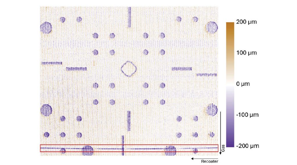
With Fringe Inspection, customers such as the US Air Force and NASA have been able to identify which anomalies cause porosity in their parts. In studies with these two organisations, a representative challenge build was designed to test the relationship between Fringe Inspection data and CT-detected porosity, a key requirement in their specifications. At the US Air Force, a build was run on an EOS M290 machine using Ti-64, and at NASA, a build was on a Colibrium Additive M2 machine using GrCop-42. The builds were measured using the Fringe Inspection system, which automatically detected anomalies such as powder streaks and hops caused by recoater-part interaction. The parts were CT-scanned to identify porosity in the final part.
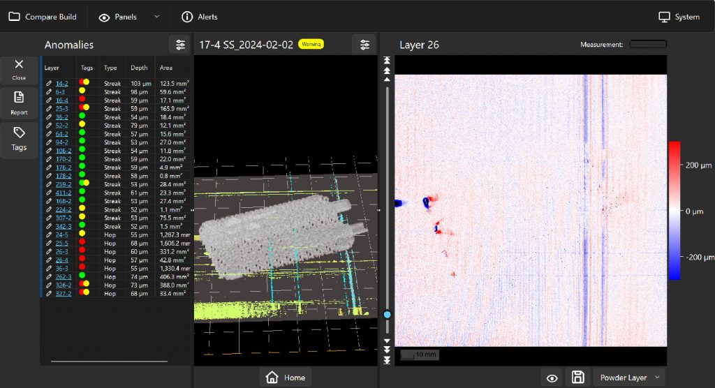
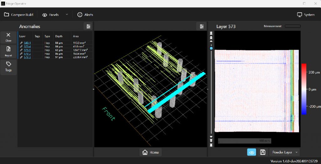
Within these builds, an anomaly generator, which is a realistic part with challenging overhangs, was included to generate recoater hops and streaks that impact parts downstream. The anomalies were detected automatically, visualised in Fringe Operator, and ranked by area and absolute height, as seen in Fig. 8.
A porosity indication table for ground truth analysis was generated using CT scans. Both studies found a high correlation between heightmap-identified anomalies and CT-detected defects. The data showed:
- For GrCop-42 and Ti-64, 83% and 81% of test specimen defects identified were correlated to layers with Fringe Inspection identified anomalies, respectively
- For both materials, 100% of Fringe Research identified anomalies ≥50 µm depressions correlated to defects detected by CT.
Additional CT-detected defects were identified in the study; however, this study only focused on correlating automatically detected anomalies by Fringe Inspection, specifically hops and streaks. Table 1 detail porosity to defect correlation for Ti-64.
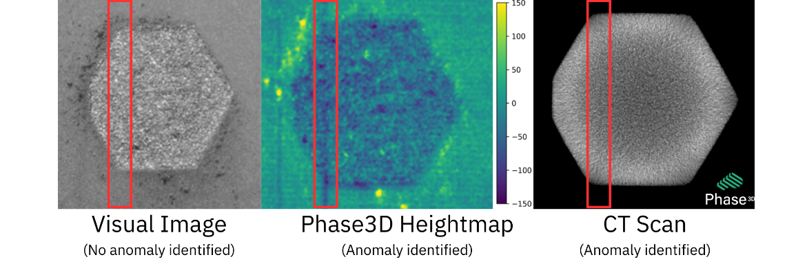
From the builds, the Fringe Inspection heightmaps were used to automatically identify many powder anomalies which correlate to pores. Many of these anomalies were not identifiable using visual images. In Fig. 9, the heightmap easily identifies the recoater streak in the centre image, which correlates to the cross-sectional CT data collected at the same height index, on the right. However, no anomaly can be detected in the visual spectrum shown on the left. This is a major risk with using optical images alone to certify builds. The visual image relies solely on shadows, which can and will be missed pending the system setup.
By identifying anomalies that cause defects in the parts, users of Fringe Inspection can control their process and get closer to certifying their builds in real time. For example, Fringe Inspection quantifies the number of anomalies correlated to defects that occur in a cubic area and can identify if and when a specified threshold is exceeded, a quality especially useful for aerospace companies using the standards established in NASA Technical Standards 6033 (NASA-STD-6033) ‘Additive Manufacturing Requirements for Equipment and Facility Control’. Using the measurements from the build, questions are removed on whether the process is in control or not, or if the build should be cancelled.
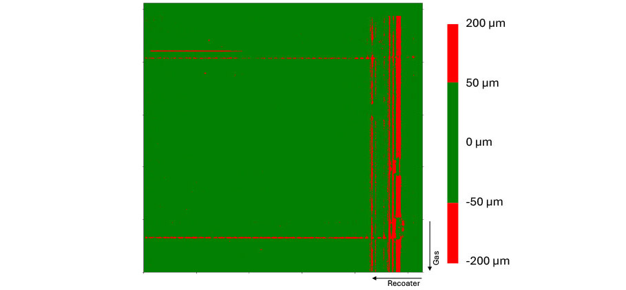
Using this process, users of Fringe Inspection can create ‘go/no-go’ criteria for their builds to know whether manufacturing should proceed. In the example layer in Fig. 10, the criteria are set so any measured area less than 50 µm is green, considered ‘good to go’, while any area that is measured greater than 50 µm is labelled red, meaning ‘no-go’ or problem detected. This is an easy way for customers to identify when the process is out of control and stop the build. This feature alone is significant for the AM industry by putting control into technicians’ hands with regards to when to fail a build.
The future of AM inspection
AM is still in its infancy in many respects, especially when it comes to real-time inspection of the process. With technologies such as Fringe Inspection, users are beginning to push the bounds on what can be additively manufactured with a validated quality guarantee. Beyond what has been outlined above, users are beginning to experiment with closed-loop control, possible with the real-time data captured by Fringe Inspection. Fringe Inspection can detect short feeds in the build process and, with the collaboration of AM machine manufacturers, a signal can be sent to the machine to spread more powder. In the future, more advanced solutions can be developed to deposit precisely the right amount of powder for each layer and ensure that it is applied correctly.

For users who seek to optimise laser paths in real-time, or ablate anomalies such as spatter particles that fall on or near the edge of the part, more advanced closed-loop controls are not far behind. These types of advancements will take time to develop and see real-world applications in industrial settings, but they are no longer impossible.
Beyond closed-loop control, exciting quality inspection for machine manufacturers and end users include IQ, OQ, PQ (Installation Qualification, Operational Qualification, and Performance Qualification) using Fringe Inspection. This technology can help first-build qualification and provide detailed analysis on whether the machine has been calibrated properly and verify that the recoater or build height actuators have not been damaged in transit. For operators, Fringe Inspection can quantify their first layer height or bed levelling. Finally, and arguably most importantly, Fringe Inspection provides the data, so every build is quantified and compared against true qualification metrics. This should be performed for every build to keep users informed about what is happening in their manufacturing facilities.
The future of AM requires inspection technologies. Anyone manufacturing using metal PBF, Binder Jetting, or Cold Spray Additive Manufacturing should investigate how inspection can help their process and stop relying on monitoring alone.
Authors
Dr Niall O’Dowd, Founder & CEO, and, Noah Mostow, Business Development Manager
Phase3D
[email protected]
www.phase-3d.com
References
[1] Patent WO2023059618A1, US11865613B2
LAST MONTH’S MOST-READ ARTICLES