


Insights from R&D to part production: How CT analysis can advance metal Binder Jetting
In the race to optimise AM technologies for the creation of both breakthrough designs and direct part replacements, it is more necessary than ever that companies have access to the deep insights and data needed to advance part designs and processing at every phase of product development. Thanks to its ability to provide these insights non-destructively and in great detail, CT analysis provides an invaluable tool for the advancement of AM processes and their adoption. Philip Sperling, Product Manager AM at Volume Graphics, explains how CT analysis can advance the development and adoption of metal Binder Jetting (BJT). [First published in Metal AM Vol. 8 No. 4, Winter 2022 | 20 minute read | View on Issuu | Download PDF]
No manufacturing process is static – either weaknesses and operation costs are addressed through continuous improvement to the core process, or competing technologies step in, upping speed, quality, costs and viability. This is certainly true in the Additive Manufacturing sphere, where Laser Beam Powder Bed Fusion (PBF-LB) is prominent and approaches such as metal Binder Jetting (BJT) and other metal AM processes seek to expand beyond their niches and make gains in series production.
Today, at private R&D sites and on factory floors, AM machines are evolving at a fierce rate, fighting to either dominate in a specialised sector or serve as a universal tool in the same style as Computer Numerical Control (CNC) machines.

Metal Binder Jetting is a fast-emerging process, promising new performance and functionality and higher productivity within its target markets. It also hopes to provide the same manufacturing agility as the more established PBF-LB process, whilst complementing traditional shape-forming and finishing technologies. At present, metal BJT typically utilises stainless steel 316L and 17-4 PH to address performance goals for industries such as automotive and aerospace, targeting, in particular, hydraulic components.
To restate a point: the AM industry is changing and improving at a blistering pace, both in the speed and size of parts made, their geometrical and metallurgical accuracy, and their repeatability for quality and volume manufacturing. Oft-repeated lists of strong ‘advantages’ and ‘disadvantages’ are expected to change as improving Additive Manufacturing technologies expand capabilities and grow past their entry markets.
For instance, the argument that support structures in PBF-LB are a key disadvantage, while generally true, is not universally applicable. A newly available generation of advanced PBF-LB machines have nearly negated this issue, with potential zero-degree wall angles achieved through careful end-to-end process control.

Porosity is a common challenge and a ‘pass-fail’ measurement for all AM machines. But, in most cases, AM provides better part density than castings, and metal BJT, at least in some quarters, is currently on a rigorous path to address porosity and related stresses through use of CT scanning and software analysis.
The role of CT analysis in Binder Jetting part development
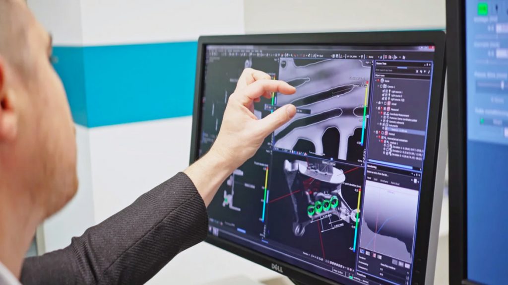
Computed Tomography (CT) analysis provides insights at every phase of product development and manufacture. Because of its ability to view interior regions of a part non-destructively, it provides valuable quantitative data on specific, critical and overall regions of a part and/or assembly. High-performance AM components usually exhibit fresh and quite novel geometries. There are unique stresses and vulnerabilities inherent in creating purely function-driven passageways and features, be it with PBF-LB or BJT.
Unlike the laser-induced heat approach of PBF-LB, Binder Jetting is driven by the interaction of powder particles, the compaction by the roller and the application of the adhesive binder. Parts are later thermally processed in two-stages to burn off the binders, reduce porosity and achieve target strengths and the desired microstructure. In the first stage of the two-step process, the ‘green’ part is debound. Next, a higher temperature is applied (usually in the same furnace) to sinter the part to its final strength. Achieving a strong green part is also crucial as prior to debinding, excess powder has to be removed and the part handled.

With evolving and mature Additive Manufacturing technologies alike, ongoing process knowledge, process inspection, and final control are paramount to success. In order to reach commercial reliability, every approach has had to move away from black-art practices and ‘recipes’ that can’t be replicated machine to machine – or even batch to batch on the same machines. Here is where CT analysis can help developers understand process causality and interrelated factors that influence outcomes. Pinpointing causes and effects can serve to aid in the use and development of sensors, feed rollers, build heads, feeders, binders, and overall operating parameters. Analysis also greatly helps in effectively addressing shrinkage, distortions, brittleness and porosity.
Early process parameter development
Early insight into build process behaviours and conditions that lead to observable and measurable trial outcomes is crucial for shortening development cycles and establishing long-term operating parameters that are reliable and deliver the highest level of productivity and, thus, commercial success. Reaching results faster in early development helps compress all the follow-on stages of product creation. It also establishes a sound methodology for continuous improvement and future expansion of machine features and capabilities.
CT analysis enables a deeper understanding in the development of metal BJT process parameters (e.g., when the user is evaluating different combinations of powder, layer thickness and binder saturation). Other testing methods, while available, are very limited and don’t give a deep volumetric insight into the green part.
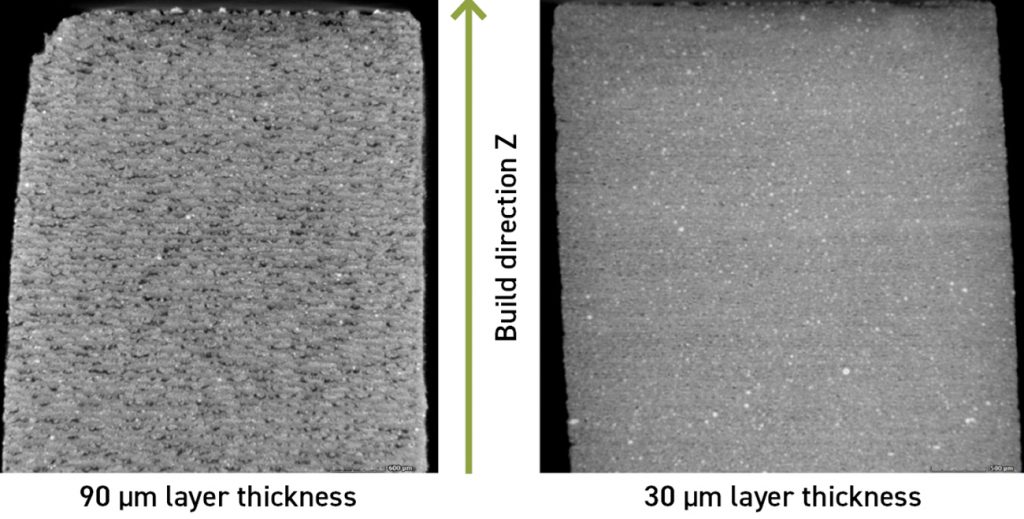
For development of early, critical machine parameters, low-resolution CT slice images (as shown in Figs. 2, 3) have proven to be excellent for overview and initial analysis. High-resolution CT slice images are comparable to microsection images and were good for targeted analyses. 90 µm layer thicknesses revealed larger inhomogeneities that later led to poorer quality parts in the post-sintering stage.
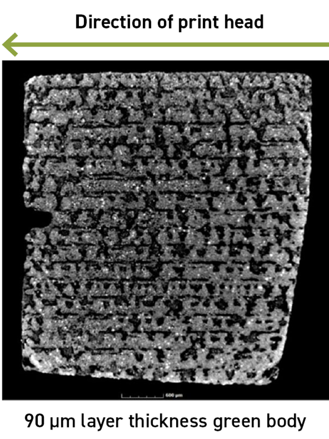
One interesting effect identified through CT analysis of binder jetted parts has been the tendency for segregation of fine powder particles in the bottom layers of a build, which leads to higher porosity (Fig. 4). This problem is caused by the tendency of finer particles to sometimes agglomerate. Understanding this behaviour allows engineers to evaluate original powder sizes in relation to layering methods and binder mixes.
Later process parameter development
The production of BJT parts incorporates several stages. These include the initial build (sensitive to layering heights, binder amounts and powder quality); low-temperature debinding (still a highly porous state for the part); and longer-cycle, higher-heat sintering to further bond the metal, reduce porosity and eliminate binder additives.

As with early-stage CT analysis, each phase of metal BJT part development can be measured via one-off scans, and batch or inline automated inspections, according to circumstances such as production controls for aerospace-spec parts. Together, early and mid-process tracking reveal these main findings:
- Density variations can be observed in sintered metal BJT parts. These variations can be traced back to the powder application by roller, the binder application itself, and the powder-binder interactions
- Binder application can lead to segregation of powder particles in one layer
- The binder application process can lead to porosity in green and sintered parts due to droplet impact. Higher binder saturation levels can compact the particle structure in green parts due to capillary forces and mechanical impact effects
With final part density, strength, and geometric accuracy so important to commercialisation —and shrinkage rates and other process impacts affecting quality and yield — in-process inspection and knowledge collection is fundamental to success.
Benchmarking and prediction
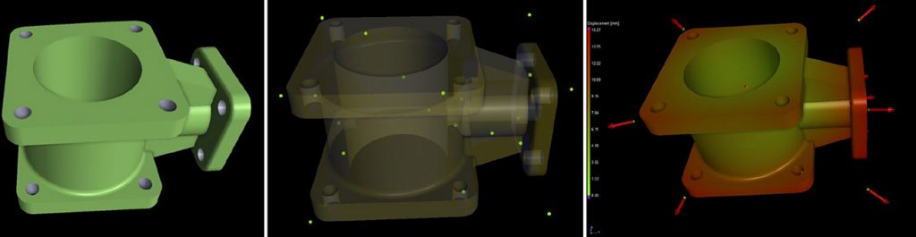
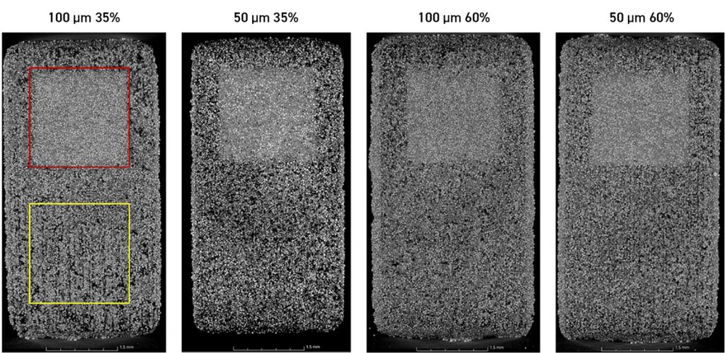
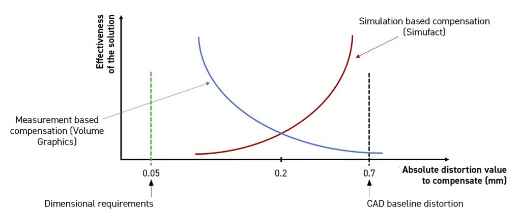
Two compatible CT software analysis approaches can help in early process analysis and geometric compensation: measurement-based and simulation-based. Measurement-based analysis serves to benchmark stages and conditions in the process leading to quantification of approaches and goals, improvements, and establishment of required, final part geometries. This approach includes comparisons between the nominal and the actual CAD tolerances and geometries against the as-manufactured part to show deviations (Fig. 5).
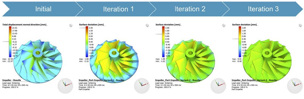
The simulation-based approach relies on prior process simulation of the shrinkage (e.g., in Simufact Additive). In such software solutions, the part geometry and shrinkage occurring during the sintering process can be simulated, allowing the part geometry to be suitably adjusted to affect different shrinkage behaviour in the X,Y and Z axes. For more complex part geometries, the simulation-based approach can be used to make increasingly detailed adaptations for complex part designs (Fig. 6).
Many challenges can be addressed using simulation, including shrinkage compensation and process adjustments, going back to powder sizes and anomalies in porosity through to aspects of curing and post-processing.
Advantages of the measurement-based compensation software approach are (1) compensation for distortions that are beyond the accuracy of simulation and (2) the ability to tackle non-uniform distortions within the build space and sintering furnace, providing machine repeatability.
Advantages of simulation-based compensation are (1) predicatively solving manufacturing problems, (2) identifying an orientation/support concept that is fit for distortion compensation and (3) the ability to iterate designs free of the cost of physical tests and numerous trial runs.
A solution for R&D and production
CT software analysis of scanned data for Additive Manufacturing processes, such as Binder Jetting, provides the insights and actionable information needed to shave years off of development efforts. It can also help to ensure that production examples reach the series quality demanded by customers. In the race to use AM for creation of breakthrough designs and much-needed, quickly produced, direct-part replacement markets, CT analysis software offers the depth, breadth and level of automation required for advancing new and evolving Additive Manufacturing technologies.
Author
Philip Sperling
Product Manager Additive Manufacturing, Volume Graphics
Heidelberg, Germany

LAST MONTH’S MOST-READ ARTICLES


