


I want to break free: The journey towards reducing or eliminating support structures in Additive Manufacturing
Support structures have been there for us since the beginning of AM, anchoring us to a firm foundation and taking the heat when things get intense. But they also bring with them baggage that is now holding us back, blocking channels and taking up valuable time and materials. Is it time to break free? In this article, Jennifer Coyne and John Barnes, of The Barnes Global Advisors, explore our journey so far with support structures, their advantages and disadvantages, and consider the opportunities and impact of the shift towards 'support free' strategies. Through three case studies, cost and productivity of conventional and 'support free' production are compared. [First published in Metal AM Vol. 6 No. 3, Autumn 2021 | 20 minute read | View on Issuu | Download PDF]
As we contemplate recent developments that minimise the need for support structures in Powder Bed Fusion (PBF) Additive Manufacturing, Queen’s 1984 hit song ‘I want to break free’ inevitably plays in our heads. In the Additive Manufacturing world, nothing elicits a strong reaction like the mere mention of supports and support structures. It’s with mixed emotions that process engineers will design them in to hold the build together until completion; but, at the same time, they know that some geometries cannot be built without supports. How do they break free?
In our minds, there is an AM pub where regular arguments break out about the best kinds of supports: pins, curtains, on and on. The group commiserates as they share tragic support removal stories of hands being punctured with tools from the 19th century. The materials engineers sit on one side of the bar and cast condescending looks at their mechanical engineering colleagues, because, after all, the supports aren’t just about mechanics: they affect the microstructure. Regular arguments break out. Supports hold the part in place! No, supports control solidification! In the shadows of the Additive Manufacturing pub, programme managers sit with crossed arms muttering about the need for a business case. Everyone wants the option to break free of supports.

In the regular world, supports, supporters and support networks are all good things. You support a colleague having a bad day – perhaps after having hurt themselves removing a block support or lost a build because the support separated and caused a recoater jam. In the Additive Manufacturing world, supports limit what can be made, because they take time to build, consume material, and cost more money to remove and dispose of, so there is a real expense associated with them. They also limit which geometries can be made, and while Design for AM (DfAM) can help reduce or eliminate the need for supports by re-examining the product requirements and consolidating parts, for some parts, where Modify for AM (MfAM) may be the only approach, the need for supports limits what geometries can be additively manufactured. And that’s an issue. Rather than improving performance by modifying the design, we are likely reducing it.
As of 2021, there are several approaches to solving these problems. System architecture has been introduced to allow further design flexibility via the ability to additively manufacture lower angles and/or eliminate external supports altogether. Software approaches exist that help mitigate the need for support through simulation and optimised orientation. Do these systems then have costs associated with them? The software approaches cost money and take time. Is ‘support free’… wait for it… free? In this article, the team has taken our data-driven approach to elucidate the benefits of these different approaches against the two situations: 1) economics – the cost to make and remove supports – and 2) design – the design freedom enabled when supports are not needed.
What is support free Additive Manufacturing?
The history of ‘support free’ is quite interesting. Originally, support free was used to describe the ability to reduce the need for supports through topology optimisation, or simply a mathematical calculation to minimise the inherent mechanical need for a support. More recently, it is being used to describe the ability to reduce or eliminate supports through the use of geometry-specific machine parameter optimisation. Multiple machine vendors now offer a support free capability.

Support free Additive Manufacturing is a subset of a priori [1] or ‘intelligent feed forward’ [2, 3] control. Feed forward involves the control of machine parameters associated with various scan patterns or geometries with the goal of minimising defects. One of the earliest reported implementations of feed forward was in 2016 [4], and one of the earliest reported uses of support free was in 2017 [5]. Commercially, one early concept was implemented by the company Realizer, called RDESIGNER. Today feed forward and support free are being implemented and actively promoted by a number of Laser Beam Powder Bed Fusion (PBF-LB) machine producers.
Reasons for supports
There is obviously a reason to use supports, so we went back and researched the origins as well as all the benefits supports offer. Supports have been in use since the earliest days of stereolithography. This earliest Additive Manufacturing technology exemplified the initial purposes of supports:
1. Keeping the part in place
As Additive Manufacturing builds layer by layer, it is vital that the position of the part being built is known, so that each layer is aligned with the one below it. If not, the part will contain stitch lines where the layers are misaligned and the part surface is notched; or, if the thickness of the feature is smaller than the misalignment, the part is discontinuous. The best way to maintain proper alignment is by affixing the part to the machine bed. Supports initially serve this role by anchoring the part to the machine bed. In the case of larger and more complex parts, especially in processes with solidification shrinkage such as Powder Bed Fusion, supports may be used higher in the build to better fixture those locations.
2. Countering recoil pressure, gravity or consolidation forces
The other initial role is in supporting downskins, which are portions of the part that do not have solid material below them. Up to a certain angle off vertical, surface tension is sufficient to overcome the effects of the laser such as recoil pressure on the powder, gravity, and surface tension. After that, however, some form of physical support is necessary. The angle and the distance are a complex function of liquid viscosity and surface tension. In the case of PBF, the properties of the powder below the melt puddle and the solidification of the puddle are also factors.

An early example of reducing or eliminating supports was achieved in the Arcam Electron Beam PBF (PBF-EB) process, developed by what was Arcam AB and is now GE Additive Arcam EBM. In this case, the electron beam is used to lightly sinter the powder bed to improve its mechanical properties to better hold the part in place and to support downskins. The development of the variants of PBF has resulted in additional reasons for supports, such as:
3. Achieving steady state
The heat extraction and stiffness of the solid build plate below the first layers differs significantly from the powder bed that is encountered for most of the part. This can be accommodated by adjusting the height and density of the initial supports below the part to allow for the first layers to see a thermal and mechanical environment more akin to that of the upper layers.
4. Consistent microstructure
Beds of powder are quite good thermal insulators, which means that parts having different thicknesses will have a variation in how the heat is extracted from the different regions, resulting in inconsistent microstructure which will then yield variation in material properties. Differences in cooling rate will result in variable shrinkage, residual stresses, dimensions, and microstructure throughout the part. Supports can be added to specific regions to improve heat extraction to better homogenise the thermal history of the part.
5. Electric current dissipation
Unique to electron beam PBF processes, the supports are used to close the electric loop by providing a conduction path to the ground plane of the machine.
The need for supports, however, impacts the design, build, post-processing, and, potentially, the service usage of Additive Manufacturing parts.
Consequences of supports
As we have noted some of the positive things supports do for us, let’s now discuss the negative consequences. Noted previously, supports have an overall impact on both economics and part design. Assessing the economic impact on the process is essential, and is useful to part design as well, so we’ll discuss the financial impact of supports first.
Economic impact
1. Build time & powder consumption
In a typical part, the build process can represent ~40% of the overall cost, whereas post-processing is ~50%, and the balance is the material cost. Using supports affects all three categories. Supports typically take the form of wasted material; they enable the process, but, unless they are somehow incorporated into the design to fulfil multiple functions such as honeycomb type supports that also serve as cooling channels, they are ultimately removed and discarded. These supports add build time and consume material that increase the total cost of the part, and the MfAM and DfAM skills required to design them out are certainly above average.
2. Post-build processing
Supports not only add time during the build process – they also are a significant driver of post-processing time. Supports can make the de-powdering process more complex, especially in the case of lattice or honeycomb structured supports that trap powder. They also add time to part handling as most supports need to be removed from the final build by machining or using hand tools (snap-off supports). They can even create hazards such as sharp edges. All of these post-processing concerns ultimately increase cost by requiring non-value added labour.
3. Unproductive use of the Additive Manufacturing machine
Fitted with our economist’s green visor and calculator, using supports can limit use of all the available production space, therefore limiting the productivity of the machine. Supports hinder the full use of the build volume, making stacking, floating or nesting of parts in the vertical direction difficult, if not impossible. Inefficient part orientations are another possible impact of supports. The requirement for a supported surface to build on also drives inefficiencies in how the build volume is used.

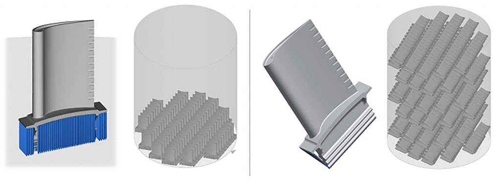
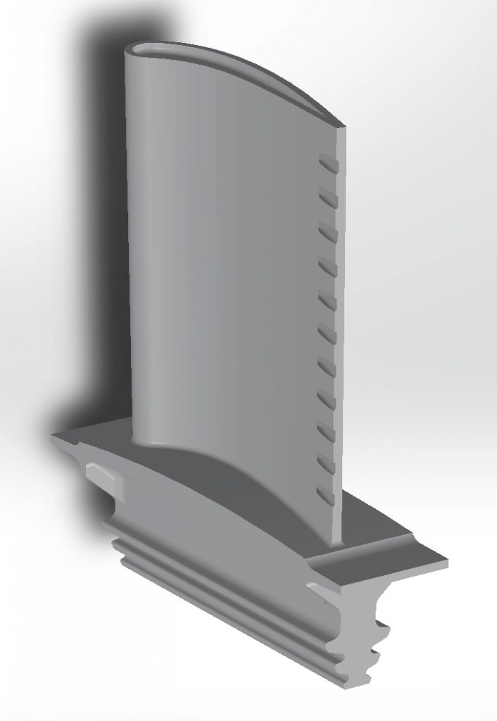
Closely associated with #3, we see that eliminating and minimising the need for supports attached to the base plate allows for higher productivity; more specifically, it increases the AM machine’s output. Electron Beam PBF and Binder Jetting technologies have always enjoyed the option to ‘stack’ or ‘float’ parts into the vertical volume of the bed. Fig. 2 shows an example of a generic turbine blade where eighty parts can be accommodated in a single layer using the traditional supports-required approach – but, when stacking is an option, the same machine can make upwards of 450 parts in a single build!
Design impact
Now that we have addressed the financial implications of supports, we will now consider their impact on part design.
1. Complexity
One selling point of Additive Manufacturing is ‘design freedom’, but, after reviewing a list of design rules such as no diameters larger than X, or strict avoidance of overhang angles > Y, a design engineer may argue that Additive Manufacturing can be quite restrictive. These design rules are specific to the process and create rules of thumb for best incorporating supports to the design to support features that may otherwise cause a build failure. They also force the design engineer to really understand the requirements of the part, such as, “do those fluid passages really need to be round?” (re: DfAM).
For the most part, this forced requirements review is a great exercise to reimagine the problem and unlock new potential or performance. Other times, when a spare part is required and any change in geometry means a system-level revalidation of performance, these restrictions can create design hurdles (re: MfAM). In either case, the time consumed chasing answers hinders the business case.
2. Surface finish
After support removal, supported surfaces may require post-process finishing to remove sharp edges and rough surfaces. Of course, some of these supported downskin surfaces may have required surface finishing regardless. When supports are removed from internal surfaces, it may affect requirements, like fluid performance, in an unpredictable way. Emerging process technologies using chemical, electro and/or abrasive methods are being used to remove supports (especially those in hard to reach internal locations) and treat surfaces at the same time.
Methods for minimising or eliminating supports
It’s clear that the need for supports complicates things; this is probably why the topic of supports is among the first listed in the cons list for adopting Additive Manufacturing. If the industry is to move forward to larger production volumes, manual processes need to be either automated or eliminated. As with most problems, there is more than one solution. We will now look at some of the support reduction methods enabling the reduction or elimination of supports.
Feed forward – controlling power and speed
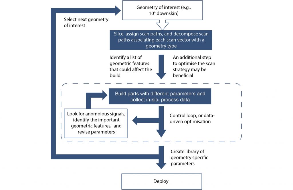
As mentioned earlier, support free Additive Manufacturing is a subset of a priori or ‘intelligent feed forward’ control. Feed forward involves the control of machine parameters associated with various scan patterns or geometries with the goal of minimising defects. Today, commercial implementation of feed forward involves parameter development by the machine manufacturer and implementation and optional tuning of the parameters by the machine owner. While these implementations are mostly proprietary, our view of how the development of process parameters might proceed is illustrated in Fig. 3.
Initially, the manufacturer identifies geometries of interest which might include inclined downward facing surfaces, thin walls, unsupported overhangs, or internal channels. The geometries are then labelled with features that characterise the geometry. Test parts that exhibit these geometries are then designed and sliced. Scan paths are generated and then decomposed into scan vectors that are associated with the features. For example, each scan vector is interrogated to see if it is over powder or solid material.
Then, initial parameters are assigned to the individual vectors based on the geometry. There are numerous features that could be used to describe the relation of the vector to the geometry. The premise is that the applied power should depend on the local thermal boundary conditions. For example, is the current scan vector over powder (poor thermal conductor) or solid (better thermal conductor)?
Vectors that are not close to boundaries are assigned bulk parameters. Vectors that are close to boundaries are given diminished parameters depending on how close they are to the boundaries. Laser power or speed are the most likely parameters to be adjusted based on the geometry. In past implementations, power has typically been selected for PBF-LB because it can be changed very quickly. For PBF-EB, speed is varied [4].
The scan vectors and associated parameters are then loaded in the machine, and test parts are built. During the build, in-situ process monitors are used to record a signal that is related to the melt pool (e.g., a photodiode signal). After the build, the part geometries are observed and the best selected. The associated process monitoring signals are reviewed for anomalies (scan vectors that are too hot or too cold), and the parameters for the scan vectors that exhibit anomalies are corrected to reduce the deviation. In the optimisation process, the list of geometric features is reviewed to identify the most important features and optimisation is restricted to those features. The build is repeated with the revised scan vectors until the parameters are optimised. Then, the next geometry is selected, and the process is repeated until all geometries have been completed and parameter sets have been optimised.
In-situ monitoring
In the case of Velo3D, a holistic hardware and software approach is taken to reduce or eliminate the need for supports. The most apparent of these is the use of a contactless recoating system. This feature eliminates one need for supports, which is to secure the part in the Z-direction to prevent the recoater from catching on any protuberances positive to the surface of the bed. The less apparent, software-driven part of this approach is in the control of the scanning parameters. By integrating geometry, a thermal/process model and process monitoring, the Velo3D approach reduces thermal stresses and distortions that can drive the need for supports.
Vector technology for thermal management
In all approaches, building without supports is an evolution in the understanding of a PBF-LB machine; a key focus is thermal management of the melt pool. SLM Solutions’ Free Float approach is an example of this evolution, which started with development of process parameters for thin features and evolved into a solution for support free Additive Manufacturing.
In this case, SLM Solutions created a bolt-on software product, compatible with newer machines, that allows users to select from three different profiles depending on the part quality and support elimination desired. After traditional build prep is complete, the slice file is loaded into Free Float and profiles are applied to the slice file.
The approach uses a vector technology to create a steady melt pool. By applying different profiles, the part has the time it needs to cool down instead of melting additional metal powder for supports. The goal is to achieve an equal build time compared to a standard build with conventional supporting, and generate savings in reduced post-processing and powder usage. The fact that the product is retrofittable to the company’s 2018+ machines shows that the secret is in the scan strategy. The breakthrough here is knowing how to control the laser power versus the geometry and packaging this power for the typical AM user in an easy control interface.
Better defined segments
An emerging approach, demonstrated by Dyndrite, further discretises the geometry and defines scan segments based on where they sit in the build volume. Imagine each layer of the 3D model having tiny segments with defined fields such as downskin, upskin, normal vectors, etc. The fields can be assigned a priority order (e.g., if a segment has both a downskin and normal vector field in it, downskins are identified as more critical and take precedence).
The tool gives the user the ability to define the important fields (based on geometry rules), query them, and combine or prioritise them, all before assigning the toolpath or parameters. The software itself doesn’t eliminate the need for supports; rather, it is a tool that allows the user to define, query, and order different sections of the geometry to treat them differently. A software engine like this could bring support free to all, even those OEMs or users without a huge software development team.
Considerations when minimising or eliminating supports
As these support elimination approaches mature, some may wonder how to eliminate supports on their existing machines. Some methods to minimise, or even eliminate, supports include careful part design, build orientation and layout enhancement, build time adjustment, parameter optimisation, in-situ process monitoring, and machine type consideration.
Part design
It always comes back to design. Reducing or eliminating supports can be achieved by following design rules (MfAM and DfAM) such as avoiding angles greater than X, hole diameters greater than Y, etc. Clever design approaches incorporate supports into the function of the part, such as structures that simultaneously support features and act as fluid passages.
Build volume use restrictions
Restrictions include the inability to stack parts and inefficient or limited part orientation options. When the design is fixed, modifying part orientation and build layout can be an effective way to eliminate or reduce supports. For example, part orientation can be adjusted to minimise unsupported angles.
Build time
Slowing down the scan speed can be an effective way to reduce the amount of heat in the part and the subsequent need for supports in some sections. This creates a trade-off between the extra time you put into the process (and path planning) compared to the time saved by reducing post-processing time of removing supports and treating surfaces as required.
New and different parameters
Adjusting machine parameters like laser power or scan strategies and speeds is another way to reduce the need for supports. These machines can have hundreds of adjustable parameters, so this method requires a very experienced user. The parameter sets that enable support free are often developed and progressed by machine OEMs. As long as the machine has the same architecture (gas flow setup, laser power, optics, etc.), the parameter sets should be transferrable between machines with the same make/model; however, using the transferred parameter sets would still require requalification of existing fixed process qualified parts.
Automated support removal
Another factor in the support equation is automated support removal. Several chemical, electrochemical, and mechanical-chemical post-processing technologies have been introduced that can not only smooth the surface of a part but can also remove supports [5]. One of these, called Hirtisation, is a two-stage process. While the second stage is used to smooth the final surface, it can be preceded by removing the supports, either before or after build plate removal. Depending on the geometry and final part surface finish requirements, it may be better to use a standard supported design and remove the supports as a post-processing operation.
Assessing the impact of support elimination
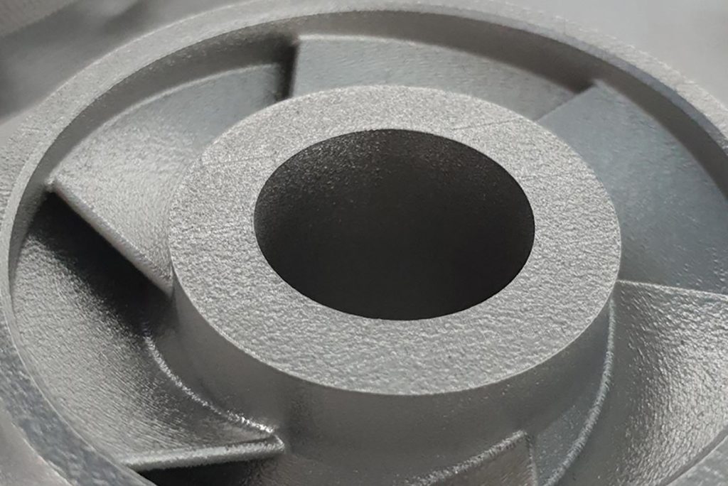
Now to the fun part! Our data-driven approach starts with several exemplar parts and two support scenarios. The parts are an impeller and a turbine blade, shown in Figs. 4 and 5, and a turbocharger, shown in Figs. 6 and 7. We first examined a scenario with standard supports, using a twin-laser 250 x 250 mm class PBF-LB machine. We then compared the Velo3D and the SLM Solutions options for minimising supports. We invited others to contribute, but they declined.
We analysed the entire part cost including feedstock, build, full post-processing (build plate and support removal, Hot Isostatic Pressing (HIP), heat treatment, surface smoothing, machining), and inspection (dimensional, NDT, and lot acceptance testing). Hirtisation is used as a semi-automated process for support removal and surface smoothing. The most economical batch sizes were used for HIP and heat treatment. Typical Organisation for Economic Co-operation and Development labour rates and a service bureau cost structure were used. Note that the same Quality Assurance (QA) cost is used for all three scenarios, although it can be imagined that the QA cost will be higher for a part with more supports to verify complete and correct removal.
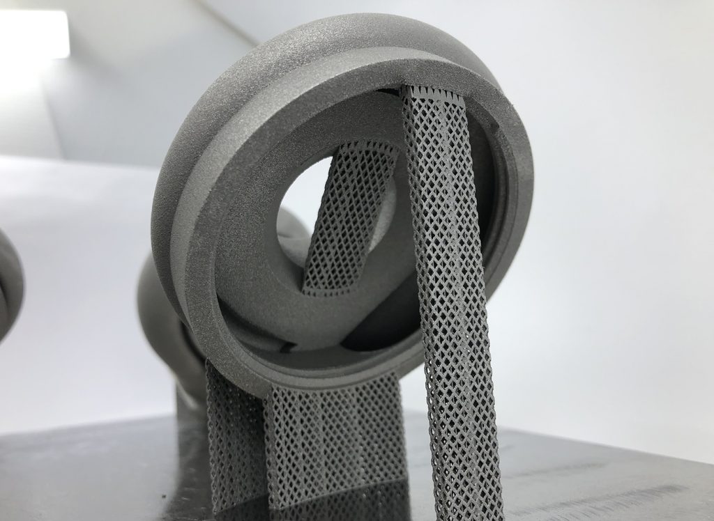
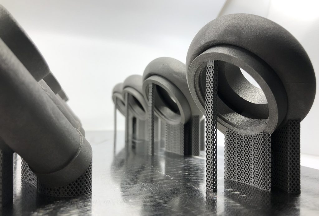
Fig. 8 shows the final part cost comparing a standard, twin-laser system with standard support concepts to the newer Velo3D and SLM Solutions minimal support scenarios.

For those interested in the details, the equipment analysed for the impeller and turbine blade employed the Velo3D Sapphire. The bed size in the Sapphire is 718 cm2, only slightly higher than a 250 mm class machine (625 cm2). The turbocharger employed the SLM Solutions’ SLM®500 Quad 700 W. The SLM®500 has a 1400 cm2 bed size compared to the standard 625 cm2.
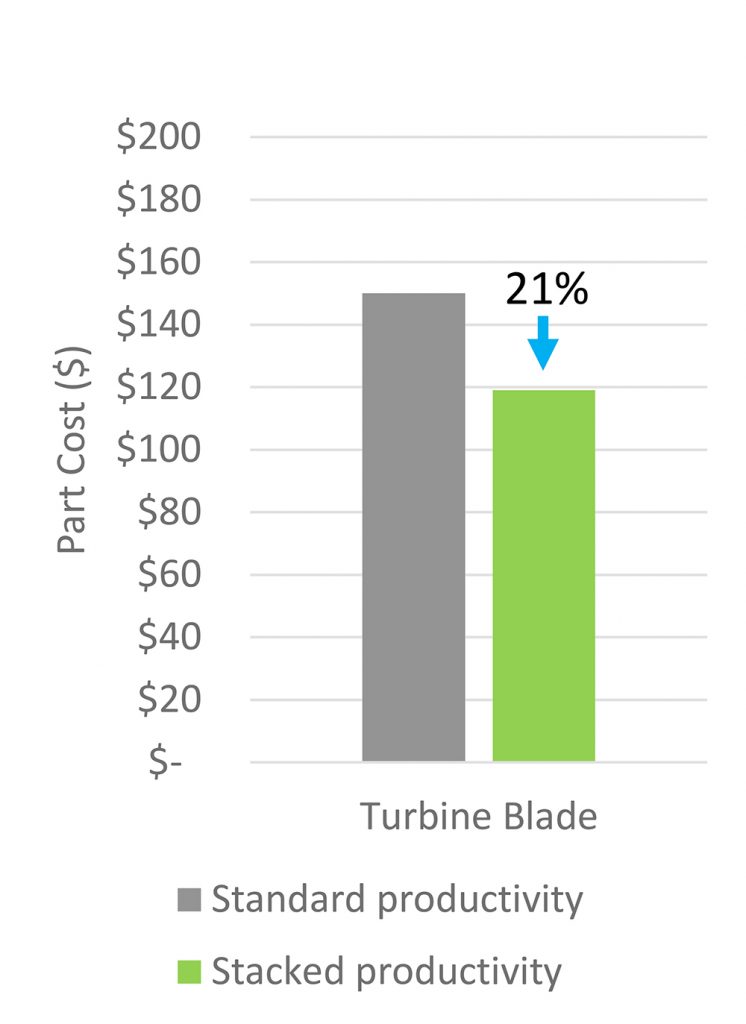
As an additional exercise, we then evaluated the impact of squeezing more productivity – i.e., output – from the turbine blade example. The minimised use of supports enabled more blades to be produced by conserving space for blades in a given layer, and also allowed use of the vertical height of the build volume. Fig. 9 shows the total change in part cost reduction from the standard support 250 mm class system with minimised supports and stacking.
In all three cases, the reduction or elimination of supports reduced the cost of the finished part, with the cost benefit being highly dependent on part geometry. Just as important, however, is that the reduction or elimination of supports, especially for internal channels, provides greater design freedom and reductions in the number of inspection steps. In the case where the elimination of supports allows for tighter part packing (i.e., the turbine blade) or where minimal surface smoothing is required, the elimination of supports will provide further cost benefit.
Conclusions
Back in the AM pub, what have we learned? Two things are now obvious to us. That minimising supports via these many methods is good for opening the design space and enabling previously difficult, cost prohibitive or just impossible geometries to be built, and that the journey we are on is enormously positive.
While the impeller has impressive part cost benefits, the turbine blade and turbocharger are moving in the right direction, though not as significantly. However, we know the technology will only get better.
A likely third lesson we can take away from this work is that, in concert with improved software, finishing methods catering to layer-wise powder builds will improve the productivity of Additive Manufacturing, which will open the application space and appease the programme managers looking for that elusive business case.
You’ll note that we fell well short of saying ‘it depends’ – which, of course, it does. The results of this work clearly indicate that geometry, part size and orientation effects play a big role. We are quite excited about these advancements, because clever people will always find a way to make the best use of new technology.
What it further illustrates is the complexity inherent in these advanced PBF AM machines. Materials science, optics, sensors, mechanics and an entire multidisciplinary team are at work every time a beam of energy hits the surface of a powder bed, requiring simultaneous optimisation, control and sensing to occur. If Queen correctly, if unintentionally, predicted that the Additive Manufacturing industry would “want to break free” of its supports by 2021, perhaps it could also signal the end of the era of “another [part] bites the dust”?
Authors
Jennifer Coyne & John E Barnes, with contributions from Wayne King PhD, Kevin Slattery DSc and Chelsea Cummings.
The Barnes Global Advisor
Pittsburgh, Pennsylvania
USA
Tel: +1 412 370 6822
References
[1] S. Clijsters, T. Craeghs, J.P. Kruth, A priori process parameter adjustment for SLM process optimization, in: P.J. Bartolo, A.C.S. DeLemos, A.P.O. Tojeira, A.M.H. Pereira, A.J. Mateus, A.L.A. Mendes, C. DosSantos, D.M.F. Freitas, H.M. Bartolo, H.D. Almeida, I.M. DosReis, J.R. Dias, M.A.N. Domingos, N.M.F. Alves, R.F.B. Pereira, T.M.F. Patricio, T.M.D. Ferreira (Eds.) Innovative Developments on Virtual and Physical Prototyping, CRC Press-Taylor & Francis Group, Boca Raton, 2012, pp. 553-560.
[2] D.L. Bourell, M.C. Leu, D.W. Rosen, Roadmap for Additive Manufacturing Identifying the Future of Freeform Processing, The University of Texas at Austin, Austin TX, 2009.
[3] W. Frazier, Metal Additive Manufacturing: A Review, J. Mater. Eng. Perform., 23 (2014) 1917-1928. https://doi.org/10.1007/s11665-014-0958-z
[4] J. Wright, Additive Manufacturing of Tungsten via Selective Laser Melting and Electron Beam Melting, University of Sheffield, 2019.
[5] Unsettled Topics on Surface Finishing of Metallic Powder Bed Fusion Parts in the Mobility Industry SAE EDGE Report 2021001 e-ISSN 2640-3540.
LAST MONTH’S MOST-READ ARTICLES


