


POWDERMET2017: Developments in powder production methods for AM
In addition to the parallel Metal Powder Industries Federation’s AMPM2017 conference, the programme for the POWDERMET2017 International Conference on Powder Metallurgy & Particulate Materials, Las Vegas, June 13-16, 2017, included technical sessions on AM. Two of these sessions were devoted to powder production methods for AM feedstocks and this report from Dr David Whittaker reviews three selected papers in this subject category. [First published in Metal AM Vol. 3 No. 4, Winter 2017 | 30 minute read | View on Issuu | Download PDF]
Titanium alloy development for AM utilising gas atomisation
The first of the reviewed papers was authored by Chris Schade, Tom Murphy and George Bernhard (Hoeganaes Specialty Metal Powders LLC, USA) and Alan Lawley and Roger Doherty (Drexel University, USA) and focused on the gas atomisation of titanium alloys for Additive Manufacturing [1].
The use of titanium in the automotive market has been the topic of numerous articles. The advantages of using titanium are its high strength to weight ratio and enhanced corrosion resistance. However, the cost of titanium, in comparison with other metal systems such as steel and aluminium, has normally precluded its use in conventional cars. Recently, due to tighter fuel usage requirements, some automotive applications such as valve guides and connecting rods have been realised, though mostly in high end automobiles where cost is not the deciding factor, but weight and performance are.
The major cost of titanium arises from the reduction of the metal from its oxide to the metallic state, which can be as much as twenty times the cost of steel. To use titanium powder in conventional automotive applications, particularly with AM as a manufacturing route, a cost-effective method for powder production is necessary.
The reported study compared two methods to produce titanium powders. The first is a commercially accepted production route, the Electrode Induction-melting Gas Atomisation (EIGA) process. EIGA requires bar stock, typically 50-60 mm in diameter, as the precursor material. The second method utilises Induction Skull Melting (ISM) or cold crucible melting, linked to a gas atomiser, to produce powders directly from raw materials, both virgin and scrap. The primary objective of the study was to utilise various forms of titanium scrap as a basis for alloy development. This was pursued on the basis of cost and the desire to measure the impurity levels and changes in chemistry that might result in the powder.

The steps in preparing any form of titanium scrap can be categorised as sorting, sizing, cleaning, sampling and inspection. The most important of these steps from a metallurgical point of view is cleaning, which includes processes such as washing (for oils and cutting fluids) and blasting/grinding (for surface contamination). Oils and cutting fluids, if not removed, can be a source of carbon, sulphur, oxygen, nitrogen and hydrogen in the final powder. If surface contamination is not removed from the scrap, non-metallic inclusions can be present in the powder, which will have a negative impact on mechanical properties.
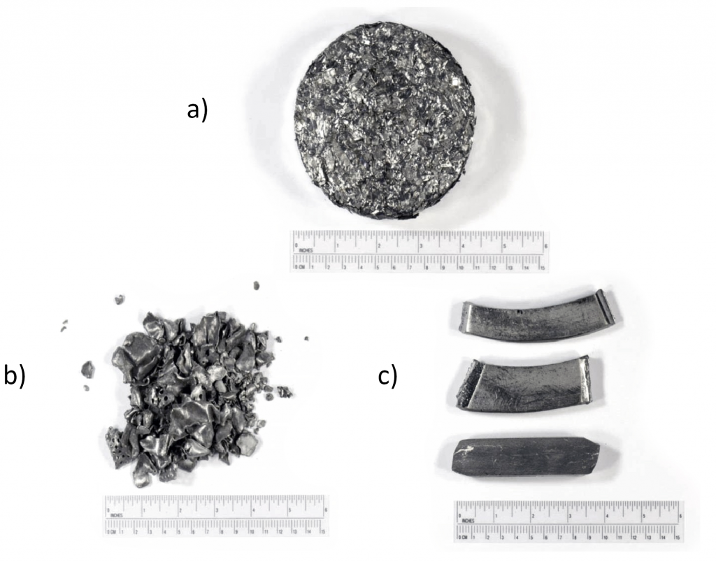
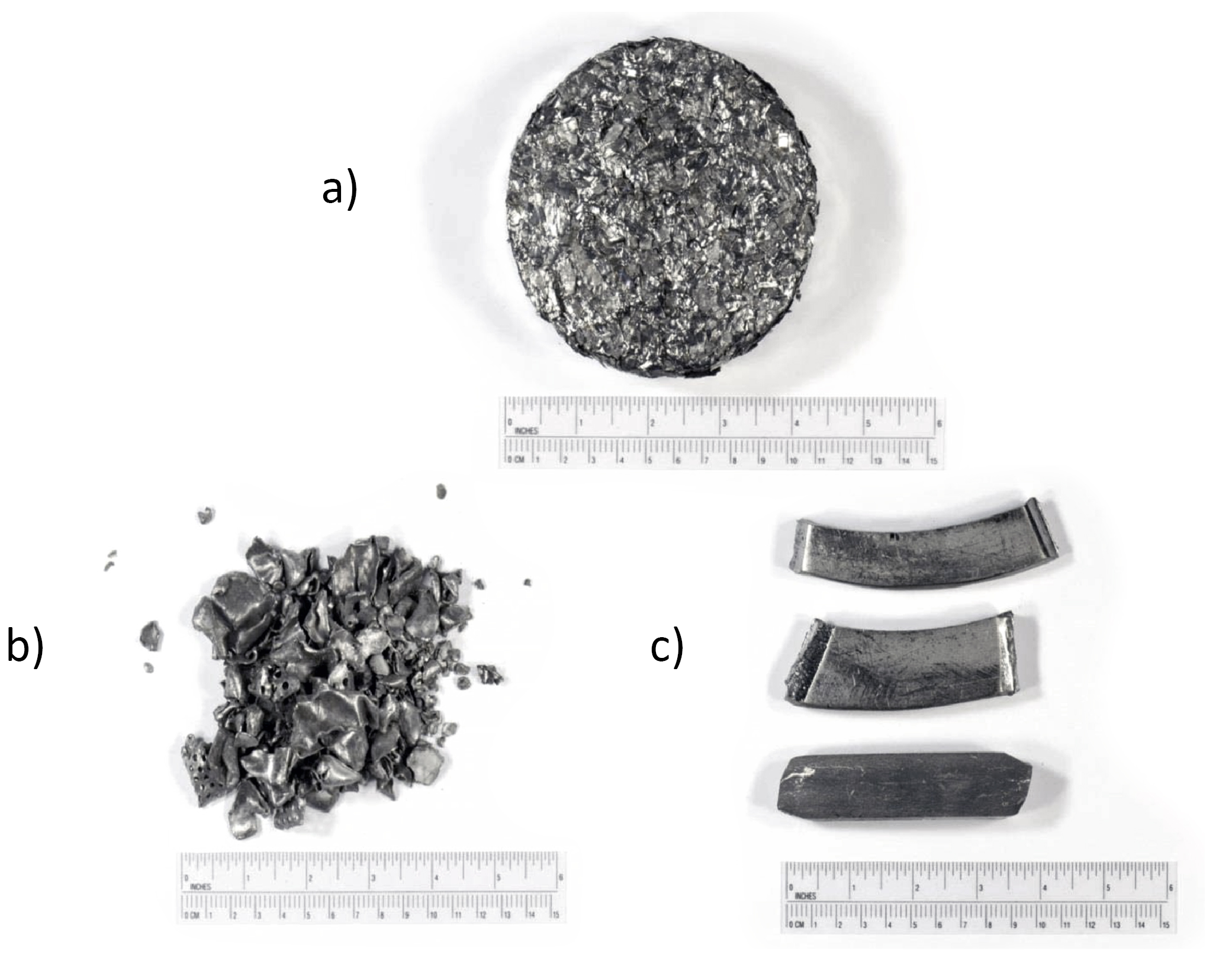
There are essentially three scrap types that are used in titanium re-melting: turnings, cobbles (shredded titanium sheet) and solids, as shown in Fig. 1. The most obvious difference between these material forms is the level of surface area and, therefore, the amount of surface oxidation and contamination that can take place (i.e. the turnings have the highest surface area whereas the solids have the least).
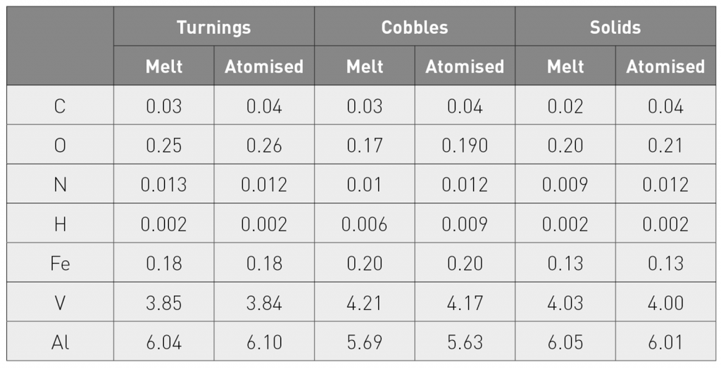
There is also a difference in apparent density for the three types of scrap. In this study, one of the first tests was to determine the consistency of the quality and chemistry of the scrap being supplied. It was also desired to understand the recovery of alloying elements and the increase in oxygen, nitrogen and hydrogen levels during the atomising process. So, 100% of the three different types of scraps, as shown in Fig. 1, were melted and the chemistry prior to atomising was analysed. This was accomplished by melting 5 kg of scrap in the ISM and then analysing the chemistry. Five different melts of Ti6Al4V were produced for each scrap type in order to ascertain the consistency of the material. A summary of the chemical results of these five melts is shown in Table 1.
The chemical compositions of the five ingots from the different scrap types had consistent chemical analyses. The highest standard deviation was found in the turnings which, as expected, had the higher oxygen content. This was probably the cause of the higher standard deviations and the lower absolute levels of aluminium and vanadium in the ingots produced from turnings, as these two elements tend to combine with the oxygen in the melt and form oxides. However, the losses of these two elements were consistent, so additions of aluminium and vanadium could be made to compensate. Another key outcome from these results was that each of the scrap types picked up very little oxygen, hydrogen or nitrogen during the melting process. The ingots produced from cobbles and solids had oxygen contents and overall chemistry that met the ASTM Grade 5 requirements for chemical composition. However, the oxygen content for the ingots made from turnings was above the maximum allowable values.

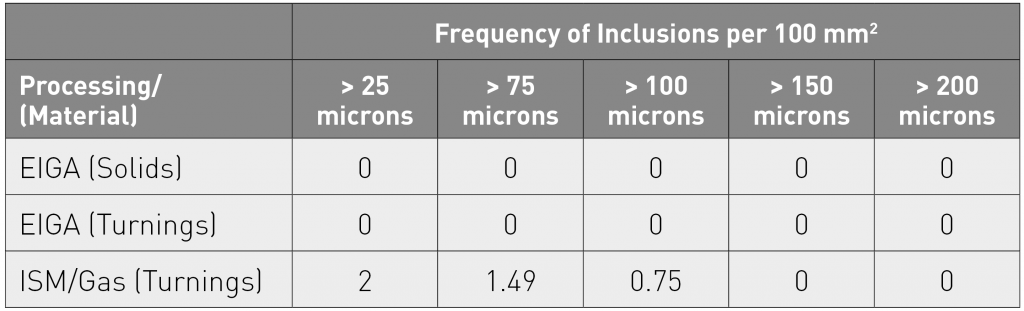
The next step was to atomise the same scraps into powder and determine the resultant chemistry and purity of the powders. The melt stream diameter was 2 mm and the atomising gas was argon. The atomising chamber was evacuated and then back filled with argon. Table 2 shows the compositions of the atomised powders relative to the starting melt compositions in Table 1 (the average of five heats). The only significant changes in composition were in the oxygen and carbon values. There was a slight increase in oxygen content (due to the surface area). The carbon content increase was attributed to the graphite pouring nozzle.
To carry out inclusion analysis, samples of the powders were sintered in an argon atmosphere to create preforms. These preforms were then re-heated (in argon) and forged into fully dense slugs, on which image analysis could be used to detect any type of inclusions. This mode of analysis is a standard quality assurance method at Hoeganaes, used to evaluate iron and steel powders used in the production of connecting rods for automobiles and other powder forged products.
The experimental atomiser used a graphite nozzle and, as a result, hard alpha inclusions can form. This precludes allowing for inclusions coming directly from re-melting of the scrap. Therefore, a trial was run with scrap using an EIGA atomiser, which does not use a nozzle but melts a solid bar in a non-contact induction coil. The same scrap previously described (Ti6Al4V solids and turnings) was melted into ingots using an induction skull melter. Bars were then used as feedstock to produce powder. The composition of the final powder was measured and found to be similar to the results shown in Table 2; there was no significant change from scrap to powder. One of the advantages of EIGA is that no refractory is used in the process. Therefore, these trials were utilised to evaluate the level of inclusions in the final powder.

Measurement of the non-metallic inclusion content was made by evaluating consolidated, pore-free metallographic specimens using an automated image analysis system. When viewed using an optical microscope, the presence of the darker non-metallic inclusions is determined by comparing the digital representation of the microstructure with a predetermined grey-scale range. Features falling within this gray to black range were detected and separated from the remainder of the image and those located within a specified distance of other detected feature(s) were joined, thus defining inclusions as the combination of the joined individual features. These features were measured and sorted into predefined size classes.
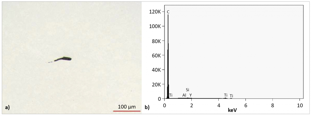
The results of inclusion testing on various powders, produced by both the gas atomising method and the EIGA process, are shown in Table 3. The powders from the EIGA process, in which there is no contact with refractories, had no inclusions greater than 25 µm. The powders produced by the ISM/gas atomising method had several inclusions between 25 µm to 100 µm in diameter. An example of the inclusions found in the ISM/gas atomising process utilising turnings is shown in Fig. 2. SEM results indicate that this inclusion was approximately 100 µm in length and was comprised almost entirely of carbon. In addition, there was a trace amount of yttria. The atomising nozzle used for this material was graphite and it was coated with yttria. All the inclusions found in this sample were of this type, indicating that, in both processes, there were no inclusions coarser than 25 µm coming from the scrap.
An experimental method for evaluating powder shape and porosity was also described. Powders for both AM and MIM are required to be as spherical as possible. In the case of AM, spherical powders provide a uniform flow of the powder from the feeder and/or pack more predictably in the powder bed. To estimate powder particle shapes, metallographic (epoxy) mounts of loose powder particles were made and analysed using an automated image analysis system.
The automated image analysis system created a digital representation of individual fields and was able to separate the metallic particle cross-sections from the mounting material by the amount of light reflected by the polished surface. The highly reflective metallic cross-sections of the particles were considerably brighter and lighter in grey, compared with the mounting material. Consequently, a grey level was established, which corresponded to the particles, and these could be separated from the mounting material for further image processing and eventual testing. Test parameters included measurement of the length, perimeter and area of each detected particle. Two of these values, the perimeter and area, were used in the following expression to estimate shape:

where A is the particle cross-sectional area and P the perimeter. This shape factor is based on the shape of a circle, where SF=1. Any particle shape more irregular than a circle or having a perimeter longer than that of a circle with the same area will have a shape SF <1. The powders, intended for use in AM, routinely have a shape factor >0.75.
The results of the measurements on the powders produced in this study are shown in Table 4. The powders produced with the EIGA process appear to have a higher circularity than the ISM/gas atomised powders. This can be partially explained by the fact that the gas atomising jet is still in the development stage, but it also appears that the ISM/gas atomised powders have significantly more satellites.
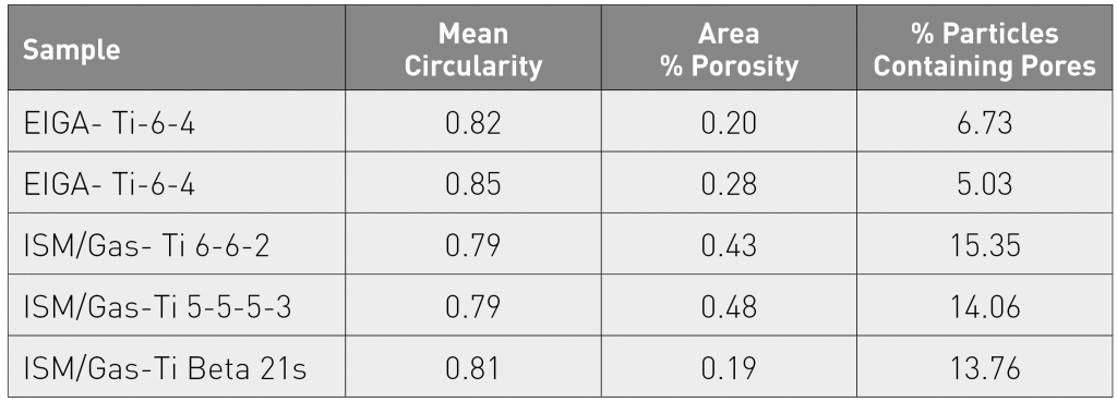
The amount of porosity in the particles can be measured during the same analysis used to estimate particle shape. This is accomplished by using the detected metallic portion of the cross-section and having the system software fill any darker, undetected areas surrounded completely by metal. These filled regions are the pores within the particles. Both the volume percent porosity in the particles and the percentage of particles containing pores can be estimated.
The area of the porosity as a function of the total area of powder and the percent of particles containing porosity is lower for the EIGA produced powders. More work will be needed to draw definite conclusions as the alloys are different and there may be other factors involved. The method developed will be useful, not only as a quality control tool, but also as a means of investigating and improving the gas atomisation process.
Finally, due to recent developments in AM, there is an interest in titanium powders other than commercially pure (CP) Ti and Ti6Al4V. When using a process which requires precursor material, this can be costly and time consuming due to the need to first melt the bar stock. With the ISM/gas atomising process, new alloys can be made quickly and in small amounts from scrap. AM processing of alloys, made from currently available scrap, may allow for cost savings, permitting their use in conventional applications, such as automotive. Therefore, a series of alloys was made utilising commercially available scrap and the ISM/gas atomising process. Alloys of interest were:
Beta 21S Alloy (UNS No. R58210)
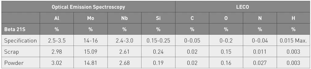
Beta 21S, which was originally developed as the matrix for titanium metal matrix composites, has been developed as an alternative to Ti-15V-3Cr and is a high strength alloy with improved oxidation and creep resistance and which can be age hardened to develop high strength. Beta 21S scrap, available in sheet form, was sheared and compacted into small pieces (1 cm and below). The scrap was then charged and melted via ISM and atomised. The chemical analysis results of the starting scrap versus the atomised powder are shown in Table 5. The increase in oxygen and nitrogen content from scrap to final powder was very low and met the final product specification typically associated with Beta 21S. In addition, the losses of volatile elements such as aluminium and silicon appeared to be minimal. There were small amount of satellites and there were grains clearly evident in the microstructure due to a slight partitioning of some of the alloying elements.
Ti-6Al-6V-2Sn (UNS No. R56620)
Titanium 6-6-2 is a heat treatable, high strength titanium alloy with higher strength and hardenability than that of Ti-6Al-4V, but with lower toughness and ductility. Segregation of beta-forming elements, such as iron and copper, is a concern in ingots, but should pose few problems in atomised powders. Metallographic assessments showed a slight increase in the number of satellites compared with the Beta 21S and a similar decoration of grain boundaries with precipitates. However, the particles also contained precipitates within the grains.
Ti-5Al-5Mo-5V-3Cr
The aerospace industry uses Ti-5Al-5Mo-5V-3Cr in the production of parts for landing gears. The ultimate tensile and yield strengths are approximately 15-20% higher than those of Ti-6Al-4V. For this alloy, a mixture of scrap and virgin raw materials was used. Metallographic examination showed a spherical shape of the particles with an indication of a possible agglomeration of the finest particles into clusters. The etched microstructure showed a grain structure somewhat different to those for the other two alloys, with the boundaries appearing more typical. The structure also appeared to show a faint dendritic texture, which was not observed with the other alloys.
Production of spherical metallic powders for AM
A paper from Jerome Pollak, Ophelie Bailly and Richard Dolbec (Tekna Plasma Systems, Canada) concentrated on the characteristics of the spherical powders produced by the company’s radio frequency (RF) plasma atomisation and RF plasma spheroidisation processes [2].
RF-PA uses metal wire or rod as feedstock, fed coaxially inside the induction plasma discharge where the material exposed to the plasma is preheated until the forward end of the wire melts. At this stage, the hot plasma gases atomise the metal in the supersonic nozzle, installed at the torch exit. RF-PS, on the other hand, can use a low-end powder (recycled or obtained from a given manufacturing process) as feedstock. As the particles passes through the plasma, they experience heating until the melting point of the material is reached and surface tension in the liquid phase enables each particle to adopt a perfectly spherical shape.
In the AM market, the requirement in terms of particle size distribution (PSD) is for powder below 150 µm and the main AM technologies have their own specifications:
- -25/+5 µm up to -63/+20 µm for Selective Laser Melting (SLM)
- -105/+45 µm for Electron Beam Melting (EBM)
- -150/+45 µm for Directed Energy Deposition (DED).
Among the different powder manufacturing processes, RF-PS offers the highest yield (>90% routinely achieved), since the PSD of the produced powder is pre-determined by properly sieving the feedstock.
The authors began by reviewing the main characteristics of RF plasmas. The first demonstration of the continuous operation of an inductively coupled RF plasma discharge can be traced back to 1961. Since then, the basic concept used for the energy coupling has remained essentially unchanged, but major improvements in torch design were made in order to adapt it to specific needs of industrial scale operations.
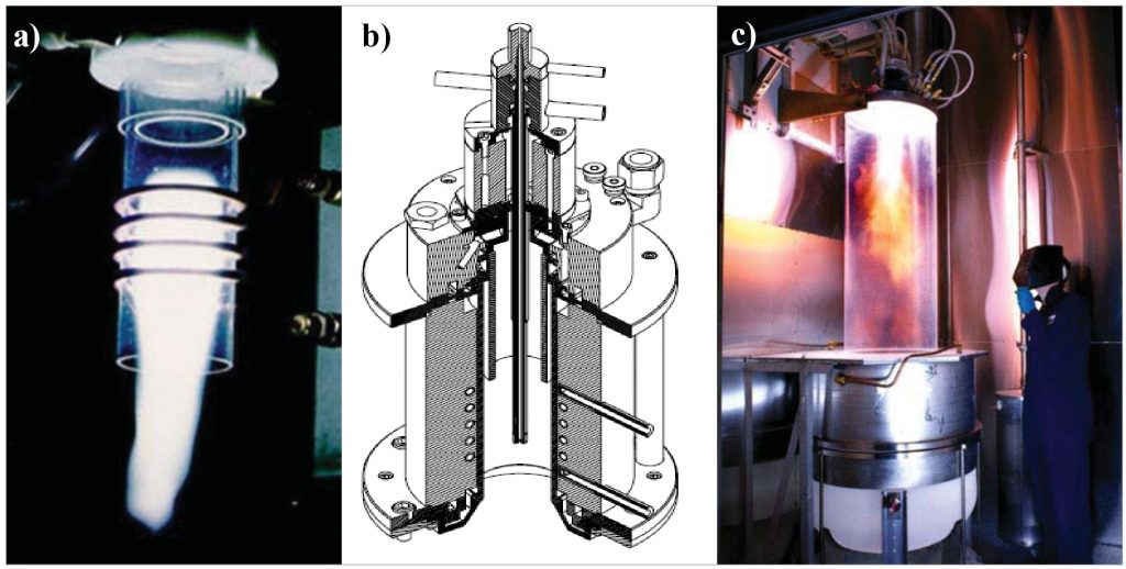
The core of the RF plasma technology is the plasma torch, capable of withstanding temperatures above 10,000°C. A typical RF plasma discharge is shown in Fig. 3a. This picture is representative of the plasma generated inside the plasma torches, commercialised by Tekna (Fig. 3b), while Fig. 3c presents an RF induction plasma system, manufactured by Tekna, in operation. Industrial RF plasmas are now confined in fully enclosed water-cooled vessels and processes are routinely used in 24/7 operating mode.
Being an electrode-less discharge, induction plasma torches do not contain parts subjected to erosion, thus preventing issues associated with powder contamination and enabling continuous production operations. This feature also allows for the operation with a wide range of gases, thus creating process conditions varying from inert (such as Ar or He for reactive metallic alloys such as Ti-6Al-4V) to reducing (Ar/H2 for materials such as Fe-based and Ni-based metallic alloys) and oxidising atmosphere (Ar/ O2 for oxides) at various operating pressures.
RF plasmas represent a very interesting technological platform for developing unique powder-related processes, including the RF-PA and RF-PS processes developed by Tekna. The most obvious difference between Tekna’s two production techniques stems from the fact that RF-PA uses a wire or rod as feedstock, while RF-PS uses a powder as feedstock, as illustrated in Fig. 4. Both processes benefit from the very high purity environment provided by RF plasmas.
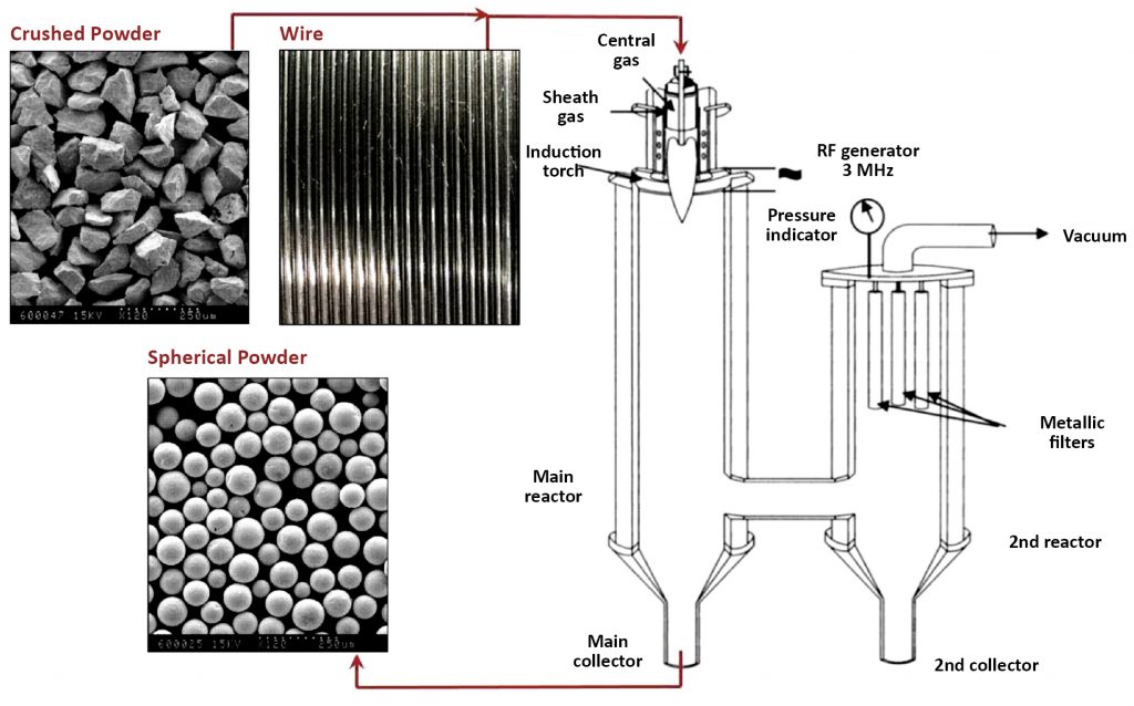
In the case of RF-PA, the fed material is melted and atomised concurrently by the hot plasma gases. The spherical particles are formed in-flight and directed downwards in a rather concentrated jet. The reactor is engineered so that particles are allowed to cool down to a relatively low temperature before they reach the bottom of the reactor. Therefore, the hot (reactive) metal is never in contact with any solid surfaces of the system at any stage of the process, ensuring the very high purity of RF-PA powders. The powder produced has a PSD ranging typically from 0 to 200 µm. Various cut sizes are then obtained through sieving for end application requirements. The RF-PA technology is used for manufacturing a wide range of dense spherical powders for AM, such as stainless steel alloys, titanium alloys, aluminium alloys and nickel superalloys.
In the case of RF-PS, the PSD of the feedstock needs to match the PSD of the spherical powder to be produced, since this technology preserves material integrity and, consequently, does not modify powder PSD. It also offers the advantage of allowing the use of feedstocks from various sources.
Each of these feedstock sources present characteristics, which are inherent to the manufacturing process. The added value that these powders gain through the application of the RF-PS process is defined as follows:
Water or gas-atomised powders
The main interest for RF-PS here is to convert the morphology into perfect spheres, while eventually decreasing the oxygen content of certain materials after plasma exposure. RF-PS also offers the advantage of densifying the particles by suppressing internal pores.
Crushed (angular) powders
A typical example is Ti-6Al-4V produced by the Hydride-Dehydride (HDH) process. This process is particularly interesting for AM. The main challenge of this process consists in maintaining or reducing the oxygen content down to values specified by the AM applications, especially for finer size cuts such as -45/+15 µm.
Sponge powders
This is the cheapest source of titanium and crushed and sieved sponge powder, processed by RF-PS, has been shown to lead to spherical powders suitable for AM.
Spray-dried powder
This is a very interesting feedstock candidate for RF-PS since various elements can be added to the spray-dried material (such as mixed carbides) and in-flight melting consolidates and densifies the particles.
Out of spec AM powders
After multiple passes in an AM machine, such as in the SLM process, certain characteristics of the powders are altered to a point where they no longer meet the required specifications. Typical changes include vaporised material condensed as ultrafine particles on the powder surface, satellites consisting of small particles of a few microns sintered on the spheres and oxygen pick up. The RF-PS process is, in fact, probably the only process offering the possibility of reconditioning such materials, depending on the material to be processed and the features to be restored. This approach has been successfully demonstrated for various materials, including CP-Ti, Inconel 718 and Co-Cr powders, for instance.
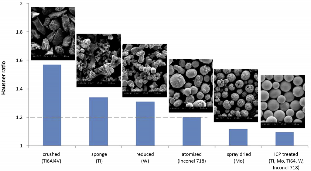
Powders produced by RF-PS always consist of perfectly spherical particles, regardless of the feedstock used, and a smooth particle surface ensures excellent powder behaviour in an AM machine. This is illustrated in Fig. 5, in which the Hausner ratios (defined as the ratio between tap and apparent densities) of various -105/+45 µm powders, manufactured by different processes, are compared. After RF-PS treatment, these powders were all found to present the same Hausner ratio of about 1.1, the lowest value achievable for this selection of materials in this size range.
A similar analysis was performed with the very same powders, but, this time, by comparing their relative apparent densities (defined as the ratio between the apparent density of the powder and the theoretical density of the material). Again, after the RF-PS treatment, these powders were all found to present the highest relative apparent density for this selection of materials in this size range. Both of these characteristics are highly valued by AM users and the significant improvements in powder properties can be ascribed to a combination of various material transformations, such as: morphology transformation from faceted to spheroidal, densification of porous materials, improvement of the particle surface smoothness and removal of satellites.
The choice between the RF-PA and RF-PS processes depends on various considerations, from both a technical stand point and a commercial stand point (feedstock pricing, targeted PSD, etc.). In the case of low-oxygen Ti-6Al-4V powder, low oxygen content wires are commercially available, while sourcing a suitable feedstock in powder form can be much more challenging, especially if Ti-6Al-4V spherical powder of the finest size cuts needs to be produced. Although both techniques are found to produce high quality and high purity spherical powders, Tekna chose its proprietary RF-PA process for the commercial production of Ti-6Al-4V powders.
Typical scanning electron microscope (SEM) pictures of Ti-6Al-4V powders (-105/+45 µm) produced by RF-PA and RF-PS are compared in Fig. 6. In both cases, the particles are spherical in shape, offering high tap and apparent densities as well as good flowability. The RF-PS powder (Fig. 6a) presents a very smooth surface, mainly due to the absence of shear forces applied by the plasma gas on the metal in the molten phase. Such a smooth surface is obtained after removing the ultrafine particles generated during the RF-PS process.
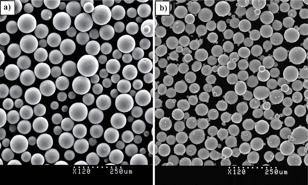
Two phenomena appear to contribute to the formation of these ultrafine particles. One comes from the portion of particles experiencing a temperature rise above the boiling point of the material due to their preferential exposure to the plasma, thus creating partial or complete vaporisation of these particles, which condense and form the ultrafine particles. The other phenomenon concerns preferential vaporisation of the alloying elements having the lowest boiling point. In the case of Ti-6Al-4V, the element with the lowest boiling point is aluminium and losses of up to 1.5 wt.% can occur, depending on the PSD of the powder, smaller particles being more sensitive than larger ones. One approach used to circumvent this issue involves enriching the feedstock with this element in proportion to the expected loss.
In Fig. 6b, RF-PA powder features some satellites on the surface of the particles. These are very small in size and limited in number, a consequence of process optimisation work, which has been facilitated by the flexibility that the RF-PA process provides in terms of processing conditions. The limited number of satellites is also due to the hot atomisation gas (as compared with cold gas used in more conventional gas atomisation processes), which minimises the risk of having smaller particles being solidified on the surface of the larger ones early in the process (i.e.at the nozzle exit), when particle concentration in the gas stream is at its highest level.
The authors’ overall conclusion was that, although RF-PA offers a better flexibility in terms of feedstock chemistry (especially in terms of oxygen content), RF-PS is a versatile process, which can cope with a wide range of feedstocks from recycled AM powders to HDH machining chips and bulk scrap.
Fundamental progress toward increased powder yields from gas atomisation for AM
Finally, a paper presented by Iver Anderson (Ames Laboratory, Iowa State University, USA) and co-authored by his Ames colleagues Emma White, Jordan Tiarks, Trevor Riedemann, David Byrd, Ross Anderson and Timothy E Prost, and Jonathan Regele (Aerospace Engineering Department, Iowa State University) reported on recent research progress towards increased powder yields and improved powder quality from gas atomisation for Additive Manufacturing [3].
While some defects that occur during an AM part build are alloy-design or build-parameter related and can be minimised or healed by post-processing, e.g. Hot Isostatic Pressing (HIP) or annealing, many defects have their origin in the initial powder feedstock and cannot be healed. These powder-related defects include internal porosity (from trapped atomisation gas) and surface impurities (e.g. adsorbed water vapour) that can degrade AM part microstructure, properties and performance. Therefore, to deliver fully the advantages of AM for metallic parts, consistent powder feedstocks with ideal properties can provide the critical experimental control needed to develop both optimal alloy designs and build parameters.
The required improvements in powder feedstocks include:
- the generation of smooth powder shapes, where spherical powders are highly preferred for their flowability and predictable coupling to energy input
- the elimination of powder internal porosity, especially in coarser powders for Electron Beam Melted AM
- improved powder surface passivation (without excessive oxide layers), particularly in fine powder size ranges for laser-based powder bed fusion.
However, in addition to the need for improved powder quality, AM process researchers and technologists have also identified the need for reduced costs in current certified feedstock powders. From the powder maker’s viewpoint, the increased cost of feedstock powders is related to the tight specific powder size distributions that are optimal for each AM process and the need to size classify the powders, usually at the top and bottom of each size range. To accelerate the growth in AM applications, custom alloy powders should be designed, developed and available in both research-scale and prototype quantities for rapid development at moderate cost.
It is widely recognised that alloy melt atomisation methods are particularly suitable for producing powders that have the most favourable flowability characteristics, i.e., sphericity, for AM feedstock, especially if powder satellite accumulation can be minimised. Of the various available atomisation methods, the Plasma Rotating Electrode Process (PREP) has been found to produce smooth spherical powders with no satellite projections and with low internal porosity content. However, PREP synthesis is a low volume and high cost technique and is really not widely applicable to most common metallic systems, especially for the fine powder size range requirements of Powder Bed Fusion (PBF).
On the other hand, gas atomisation is the leading industrial process for high-volume, low-cost production of pre-alloyed metallic powders in a broad range of powder sizes. However, several process research challenges must be overcome for gas atomisation and specifically for close-coupled gas atomisation (CC-GA) with the most promise for precise atomisation control, to meet the powder needs for full-scale commercialisation of gas atomised powders for development of robust AM parts.
In the reported study, the authors chose to study a Ni-based superalloy, well recognised for its application in harsh and extreme environments, MAR-M-247, but one that is very difficult to process by AM due to its tendency for weld cracking.
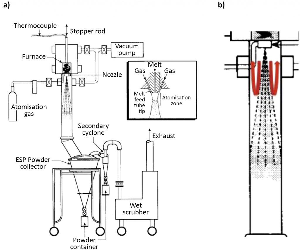
In the experimental study, the charge was a combination of pure metals and master alloys, using high purity (99.95%) elements with a total charge weight of 20 kg. The alloy composition was a low carbon (0.075%) version of MAR-M-247 (59.335%Ni-0.15C-8.25Cr-10.0Cr-0.7Mo-0.5Fe-5.5Al-0.015B-1.0Ti-3.0Ta-10W-0.05Zr-1.5Hf wt.%). The atmosphere in the melting chamber and atomisation system (Fig. 7) was evacuated with a mechanical pump to < 26.6 Pa, prior to backfilling to 111 kPa with ultra-high purity argon. The molten alloy was contained in a bottom tapped yttria-stabilized zirconia (YSZ) crucible with an alumina stopper rod (coated with yttria paint) to seal the exit of the YSZ pour tube, while heating to a pouring temperature of about 1700°C. When the desired superheat was reached, the stopper rod was lifted and melt flowed through the YSZ pour tube with a trumpet bell interior profile. The melt exited the pour tube orifice (3.8 mm) and was atomised with argon from a gas atomisation nozzle, having a jet apex angle of 20 degrees with 36 cylindrical gas jets, each with a diameter of 1.32 mm arrayed around the axis of a 21.34 mm central bore. The argon atomisation gas supply produced a nozzle manifold pressure of 896 kPa. Secondary gas halos of argon and helium were added to the interior of the spray chamber at various downstream locations for additional cooling of the atomised droplets and/or for surface oxidation, to passivate (and prevent coalescence of) the resulting powder.
Recent results were encouraging in terms of the suppression of large internal porosity from trapped atomisation gas and minimisation of satellite projections on as-atomised powder particles.
Suppression of the entrapment of atomising gas in the powder making process requires the use of an alternative atomisation mechanism with lower energy than the ‘bag break-up and collapse’ mechanism. As the authors have described in a previous publication, there are several types of ligament and direct droplet formation mechanisms that lead to instabilities and droplet pinch-off without any apparent opportunity to trap atomisation gas. However, it remains a challenge to develop the gas atomisation configuration and parameters that promote only these lower energy droplet formation mechanisms, while avoiding bag break-up and collapse.
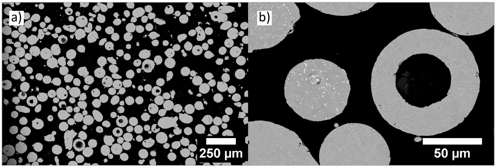
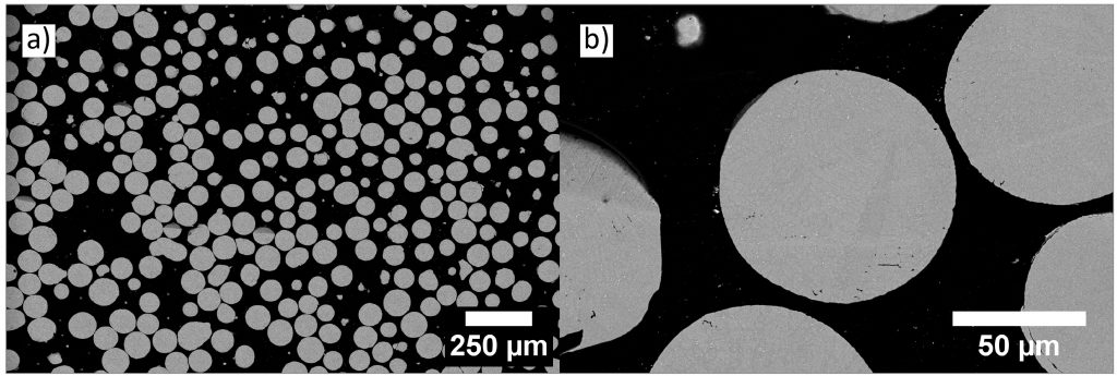
SEM examinations of batches of commercial powders from two different suppliers showed that 28% of powder particles contained trapped internal porosity for vendor A and 21% for vendor B (Fig. 8). Results from the Ames laboratory atomisation experiment indicated that progress towards suppression of internal porosity by using gas with a reduced kinetic energy had been achieved, with only 4% of powder particles containing trapped gas (Fig. 9).
Another type of internal porosity that can persist in AM builds, in spite of post-build HIP consolidation, is derived from sphere-like powder shapes that are decorated by ‘satellite’ projections. This type of retained porosity in builds is especially troublesome for AM methods such as laser melting and EBM/PBF. Unlike the gas porosity trapped inside spherical powders, satellite-decorated powders will encounter problems with a lack of smooth, continuous ‘flowability’ when tested in gravity-induced flow out of a funnel, either Hall or Carney, when propelled by a carrier gas in the narrow tube from a powder feeder, or when spread as a fresh layer on a powder bed of a controlled height by a roller or ‘doctor blade.’ The latter two of these types of flowability problems can produce lean regions on the basis of a lower powder flux flowing into the molten zone of a DED system or scattered clusters of unoccupied void space in the settled layers of a powder bed fusion system.
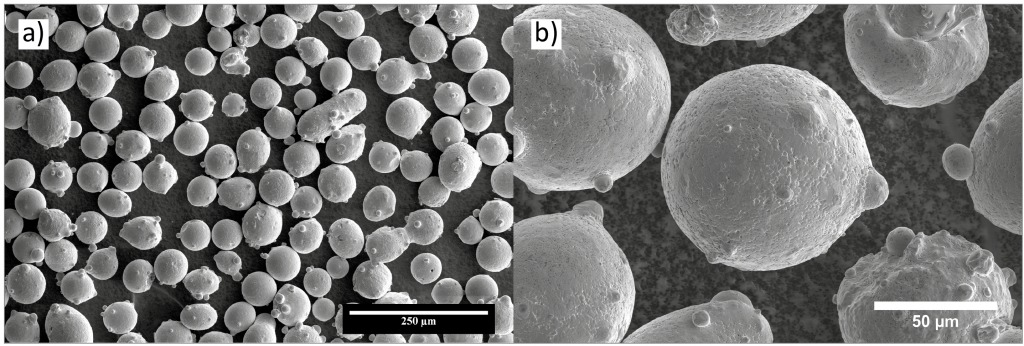
Examination of one of the commercial samples also showed that particle shape was fairly spherical at low magnification, but there was a noticeable population of satellite projections in the higher magnification image (Fig. 10). After producing an experimental batch of a very similar alloy within the narrow spray chamber (30 cm inner diameter) of the Ames Lab pilot-scale gas atomisation system (Fig. 7), SEM analysis of the as-atomised powder (see Fig. 11) indicated that satellite decoration was greatly reduced in this experiment.
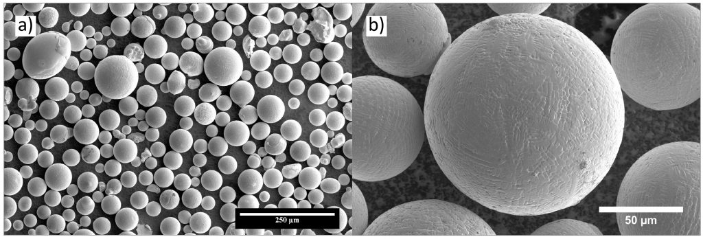
It seems possible to attribute the high degree of sphericity of the powder in Fig. 11 to the narrow spray chamber of the Ames Lab system (see Fig. 7 ) that limits the external recirculation flow effect, but it is still possible for classic satellite formation mechanisms to operate. Thus, more modelling on the influence of the spray chamber design and experiments to verify these results must be performed in order to perfect the satellite suppression effects that seem very promising in the initial experiment.
References
[1] Titanium alloy development for AM utilizing gas atomization, Schade C et al. As presented at the POWDERMET2017 International Conference on Powder Metallurgy & Particulate Materials, Las Vegas, USA, June 13-16, 2017, and published in the proceedings by the Metal Powder Industries Federation (MPIF).
[2] Production of spherical metallic powders for AM, Pollak J et al. As presented at the POWDERMET2017 International Conference on Powder Metallurgy & Particulate Materials, Las Vegas, USA, June 13-16, 2017, and published in the proceedings by the Metal Powder Industries Federation (MPIF).
[3] Fundamental progress toward increased powder yields from gas atomization for Additive Manufacturing, Anderson I et al. As presented at the POWDERMET2017 International Conference on Powder Metallurgy & Particulate Materials, Las Vegas, USA, June 13-16, 2017, and published in the proceedings by the Metal Powder Industries Federation (MPIF).
Author
Dr David Whittaker
Tel: +44 1902 338498
Email: [email protected]
Proceedings
Advances in Powder Metallurgy & Particulate Materials – 2017, the proceedings of the technical sessions, poster program and special interest programs (where applicable), is published in digital format by the MPIF. These can be purchased from the MPIF’s Publications Department.
POWDERMET2018
POWDERMET2018, the International Conference on Powder Metallurgy & Particulate Materials, will take place in San Antonio, Texas, USA, from June 17–20, 2018. A Call for Papers & Posters has been issued and the abstract submission deadline is November 3, 2017.
LAST MONTH’S MOST-READ ARTICLES


