


Design for Additive Manufacturing (DfAM): Binder Jetting Technology demystified
Able to achieve quicker build speeds and lower cost per part than its rival technologies, metal Binder Jetting (BJT) has generated increasing interest and rapid industry investment over the past two years. But while many engineers are now becoming familiar with the principles of design for Powder Bed Fusion AM, design for BJT is less widely understood. In this article, Olaf Diegel and Terry Wohlers attempt to demystify some of the key factors that must be considered when designing parts for BJT. [First published in Metal AM Vol. 6 No. 2, Summer 2020 | 10 minute read | View on Issuu | Download PDF]
Over the past two years, a lot of interest has developed in the use of metal Binder Jetting (BJT). Desktop Metal, HP Inc. and others have generated much of the attention this class of AM technology is getting. While some may be under the impression that metal BJT is a relatively new AM process, it has been commercially available for nearly two decades from The ExOne Company. Höganäs’s Digital Metal was second to make its BJT technology available, first as a service and more recently by selling machines.
BJT offers some potential advantages over alternatives such as metal Powder Bed Fusion (PBF), with cost being one of them. Taking everything into account, the cost per part can be lower for small parts produced by BJT. Build speed, too, is fast compared to some competing AM technologies, which also factors into its lower cost. BJT may offer cost and speed advantages, but one needs to consider other factors, such as the part shrinkage that occurs during sintering. Depending on the process, metal and method used, shrinking can range from 3% to more than 20%. Because errors from shrinkage magnify with size, and controlling it is difficult, users of BJT tend to favour the technology for the production of small parts. Porosity and structural integrity are also considerations in BJT.

How metal BJT works
A layer of metal powder is deposited onto a build platform and a liquid binder is then applied using an inkjet nozzle to form the shape of a slice of the part design. Where the binder is applied, the powder particles in the layer bond together. The build-platform is then lowered, a new layer of powder spread on top, and the process repeates until the part geometry is completed within the powder bed. After completion, the build platform is raised and the loose powder removed. Green parts must then be sintered into solid metal parts.
The BJT process involves the following steps and considerations:
1. Binder Jetting
A machine deposits thin layers of metal powder onto a build platform and applies a binder (i.e., liquid glue) layer by layer. The minimum feature size for metal BJT is typically in the range of 2 mm. The process can be used to produce details as small as 1 mm, but these features are difficult to handle without damaging them. This applies to both features and text on a part.

2. The ‘green’ state
After the building phase is complete, the parts are in a fragile ‘green’ state. It is important to consider the design of a part to ensure it can be handled during this temporary but critical phase. Green parts can be picked up, but they have little strength and can easily be broken.
3. Powder removal
Loose powder around the parts is carefully removed by brushing and/or vacuuming as part of a depowdering process to fully expose the green parts.
4. Debinding and the ‘brown’ state
In the case of most BJT systems, a debinding process is needed to remove the main part of the binder system. The parts are placed in a furnace to burn away the binder, resulting in ‘brown’ parts. These are extremely fragile and will crumble if touched.

5. Sintering
The parts are heated in a furnace until the particles of the metal sinter and form a solid. Significant shrinking occurs with during this phase, but the result is a homogeneous part. Sintered BJT parts typically have some internal porosity, and are often around 97% dense. This means their as-sintered mechanical properties are inferior to the same material in wrought form. As a point of comparison, metal PBF parts can be 99.5% dense. It is common, however, for high volumes of sintered parts produced by Metal Injection Moulding (MIM), technically similar to metal Binder Jetting, to undergo Hot Isostatic Pressing (HIP) to produce full dense parts. There is little reason why this step cannot also be applied to BJT parts, should the application require it.
Is shrinking the curse of metal BJT?
It is important to understand that parts shrink, often significantly, during the sintering step to consolidation to near full density. This is one of the biggest factors to consider when using BJT for production. The level of shrink will vary between various systems, depending on the volume of binder used. The MIM industry learned to embrace this aspect of the technology over several decades and successfully produces hundreds of millions of parts annually for everything from superalloy stator vanes to the stainless steel buttons for smartphones. In BJT, the software provided by machine manufacturers attempts to compensate for shrinkage in the CAD model, but many external factors contribute, including the part design and sintering furnace parameters.

Proper part size and design makes a big difference
Some companies recommend BJT only for small parts, typically less than 5 x 5 x 5 cm. Suppose a part measures 10 mm in length and dimensional error from shrinkage is 1%. The resulting error is 0.1 mm, which may be within an acceptable tolerance. If a part is 300 mm in length, the error from shrink is 3 mm, which is less likely to be within an acceptable tolerance. The silver lining to this cloud is that when a part shrinks, extremely small features also shrink, effectively increasing resolution. In this way, you are able to plan for details that are finer than is otherwise possible, with improved surface resolution.
Part design is a factor that a designer can control. The key design guideline for BJT is to avoid large masses of material or uneven wall thicknesses. These can cool at different rates, so they are more likely to cause the part to distort or shrink unevenly.
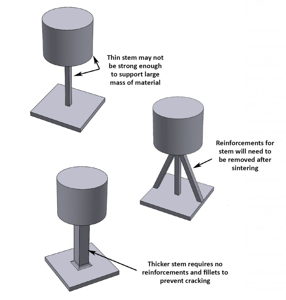
BJT does not have the same support material requirements for overhangs or down-facing surfaces as PBF. Consequently, the down-facing surface quality of BJT parts is typically better. Gravity, however, is the enemy during sintering and whilst PBF-style supports are not required, some designs may need to be adapted with reinforcements against slumping when sintering.
Fillet and round everything
A general design guideline is to avoid sharp edges. If possible, fillet and round all internal and external corners. Sharp external corners and knife edges can chip and crack when depowdering, handling, or heating while parts are in their green state. Rounding the edges with at least a 0.5 mm fillet prevents parts from breaking (Fig. 2). If required, sharp edges can be recreated when post-processing the parts.
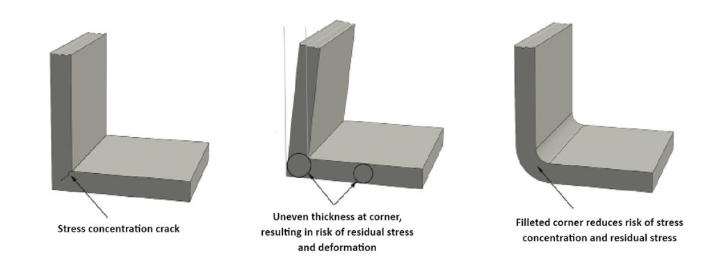
Internal corners are where stress concentrations occur, so filleting them reduces the problem and improves the overall structural strength of a part. Stress concentrations may cause a part to fail prematurely and residual stress may cause distortion in a part when sintering.
In the simple part shown in Fig. 3, the sharp internal corner may cause a stress crack. Also, the sharp corner has a larger mass of material than the horizontal and vertical walls, resulting in residual stress that can cause the wall to distort. A filleted corner and an even wall thickness reduces the possibility of a stress fracture.
Fragile metal BJT parts
Until parts have been fully sintered, green BJT parts are very fragile, so the entire design must take this into consideration. Poor design may result in parts being damaged during handling, e.g. to move to a debinding unit. Because of this temporary fragility, certain shapes and geometric features cannot be used. If they are, a part may be built without a problem, but you may not be able to handle it in its green state. It is often necessary to include strengthening ribs or walls in a design that support handling (Fig. 4).
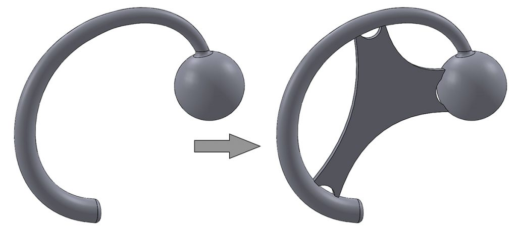
Fig. 5 shows three different designs of the same part, with significant differences in the stem design for greater green strength.
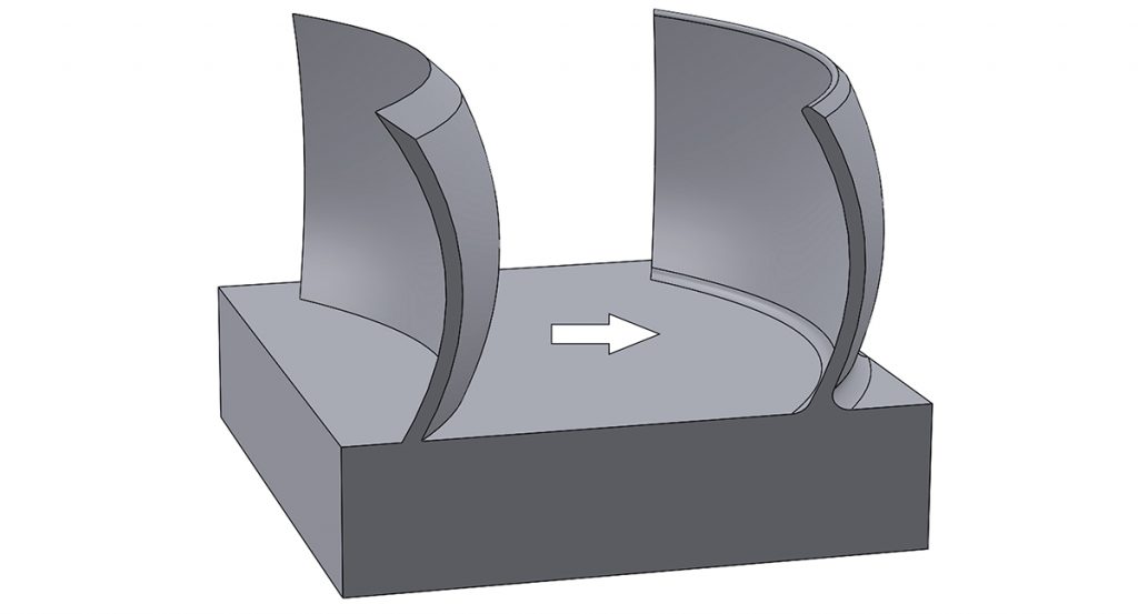
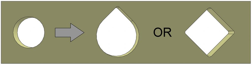
Horizontal holes
With BJT, building parts with circular horizontal holes can be problematic because the weight of the material above the hole will compress its shape downward during the sintering process. This is particularly severe when large masses of material are above the hole. If a distorted pipe is straight, it can be made round by a subsequent drilling operation. If the pipe is curved, achieving a round hole can be difficult. For this reason, it is better to use teardrop or diamond-shaped holes whenever possible.
In general, round holes larger than 6 mm in diameter may distort heavily, so teardrop or diamond-shaped holes are recommended (Fig. 6). The smallest horizontal holes that can be additively manufactured with BJT are about 0.7 mm when infiltrating bronze. For fully-sintered, homogeneous parts, the smallest is 1.2 mm. Average powder particle size also plays a role in the hole size that is achievable.
Additional thoughts
BJT can be less expensive for producing relatively large volumes of small parts, compared to PBF. When using laser-based PBF in particular, parts cannot be stacked or nested easily, which is possible with BJT. This makes it possible to use a machine’s entire build volume by stacking parts in the vertical direction. The build speed of BJT is also typically faster than with PBF. If plenty of sintering furnace capacity is available for the green parts, the overall production time is attractive.
It is impossible to conclude whether BJT or PBF are better or worse because both have their benefits, pitfalls, and design considerations. Both require strong knowledge of the process and material to design for an optimum outcome. BJT is relatively new for production applications where structural integrity is important, however those familiar with MIM can call upon that industry’s experience and research. PBF is being used much more extensively for production, even for some structural applications. The key is to understand the idiosyncrasies of each process and where they can add value to make the process commercially viable.
Authors
Olaf Diegel and Terry Wohlers
Wohlers Associates Inc
OakRidge Business Park
1511 River Oak Drive
Fort Collins
Colorado 80525
USA
www.wohlersassociates.com
Acknowledgments
Parts of this article were excerpted from Olaf Diegel’s book A Practical Guide to Design for Additive Manufacturing. Thanks to Gianluca Mattaroccia, Engineering Fellow at the Estée Lauder Companies, for reviewing this article.
A well-established technology variant:
Binder Jetting and infiltration to produce matrix materials such as ~ 60% stainless steel and ~ 40% bronze
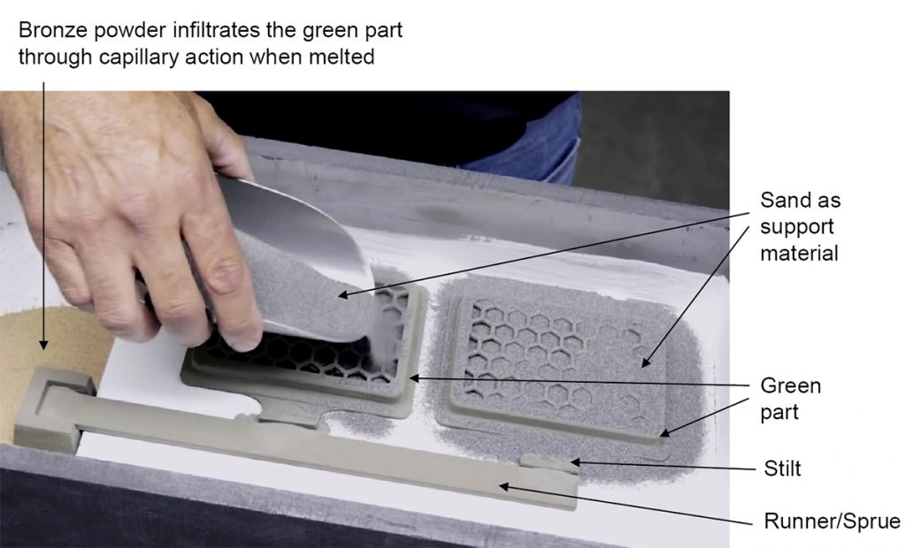
Once a green part has been produced, an alternative to sintering is infiltration by a second material, such as bronze. The lower hardness of these materials makes it easier to machine and polish them. They can also exhibit useful corrosion resistance properties.
When processing in this way, sprues and stilts need to be added to the part design to serve as passages that allow a molten metal to infiltrate. Since they are still in a green state and fragile, they are fully surrounded with sand, which acts as a temporary support material. The model is then infused with bronze at a high temperature, resulting in parts that are a two-alloy matrix. In the case of a stainless steel/bronze part, the material ratio will be in the range of 60–70% stainless steel and 30–40% bronze. Infiltrated parts will typically be about 90% dense.
The sprues and stilts typically have a surface area of about 1–1.5 mm where they connect to the part, so the artefacts left by these stilts and sprues after infiltration require finishing, usually by machining. Any residual powder around the model is removed by blasting it with air. Care must be taken to not damage delicate features.
As the infiltration process can be labour intensive, its opportunities for high volume production may be limited, compared to Binder Jetting followed by conventional debinding and sintering.

LAST MONTH’S MOST-READ ARTICLES


