


Design for Additive Manufacturing: Increasing part value through intelligent optimisation
Paying the right amount of attention to Design for Additive Manufacturing (DfAM) can make the difference between economic success and failure. When considering Additive Manufacturing for production applications, it is important to consider designing, or redesigning, parts that would otherwise be produced using conventional manufacturing. In this case study, Terry Wohlers and Professor Olaf Diegel, both of Wohlers Associates, reveal how industrial mining machine manufacturer Atlas Copco has used DfAM to increase the value of a hydraulic manifold. [First published in Metal AM Vol. 3 No. 3, Autumn 2017 | 10 minute read | View on Issuu | Download PDF]
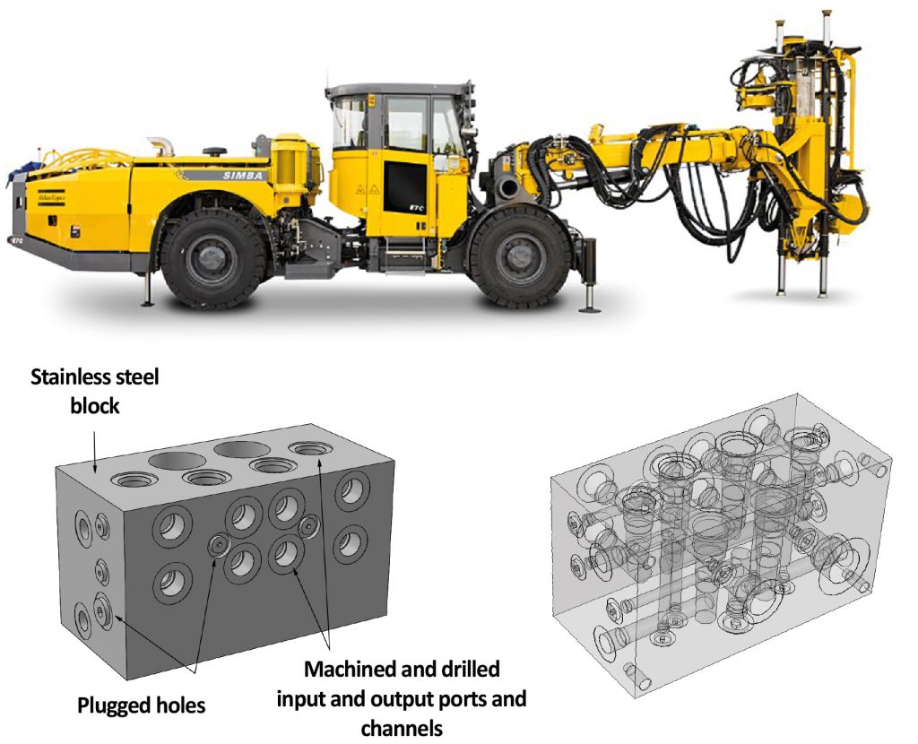
Atlas Copco, an industrial tool and equipment manufacturer headquartered in Nacka, Sweden, has been exploring DfAM as it considers the move from traditional manufacturing to AM to add value to its products and production processes. One application example is a hydraulic manifold used on one of its underground drilling rigs (Fig. 1). The company is particularly interested in using AM to substantially reduce the weight of the manifold’s parts while improving its functionality. Because the manifold is mounted at the end of the rig’s extendable boom arm, reducing its weight could add substantial value to the rig’s functionality. A project to redesign this manifold for AM was carried out by Fredrik Andersson, Magnus Karlberg and Sima Valizadeh of Atlas Copco, together with Lund University Master of Engineering student Henrik Nilsson, who led development.

The hydraulic manifold, currently manufactured by CNC machining, consists of a block of stainless steel into which a large number of connecting holes are drilled. They form a number of interconnecting channels through which hydraulic fluid flows to the proper ports. Valves and sensors can also be attached to measure pressures. When using conventional manufacturing, the only way to produce connecting channels inside the block is to drill holes from the outside of the block and then plug them so that the internal channels remain.
Support structures as a key consideration
One of the most important goals of designing for metal AM is to reduce the amount of support material used when printing the part. With metal AM, support material is used to anchor the parts to the build plate during printing and to transfer heat away from the parts. This approach reduces the possibility of distortion of the parts from the extreme heat. In particular, it is important to avoid support material in any internal features, such as the channels of the manifold, as this can be difficult or impossible to remove. Typically, any feature that is more than a certain angle from vertical, such as 45° (the exact angle varies depending on the material being printed), will require support material. A wall can be used as a feature of the design to avoid support material while also improving the strength and rigidity of the part.
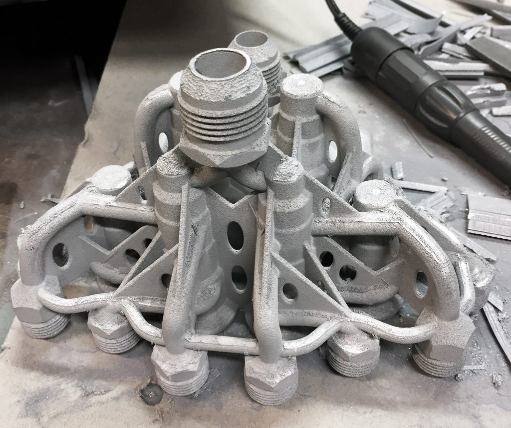
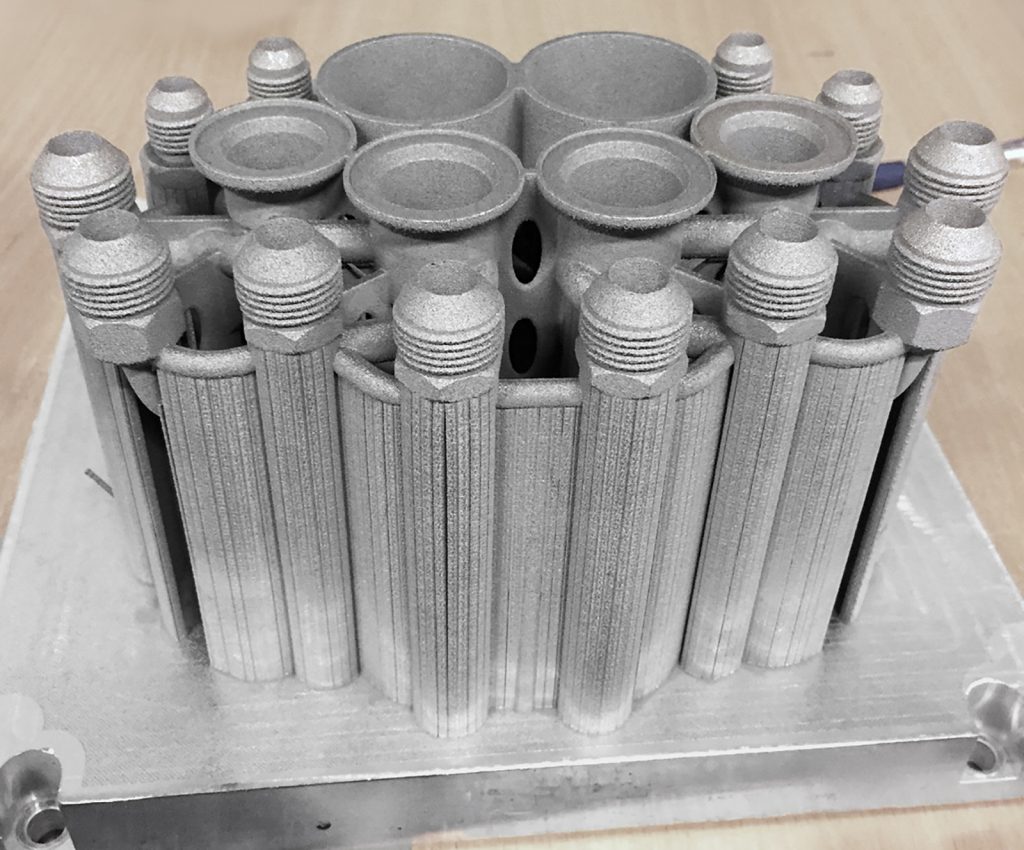
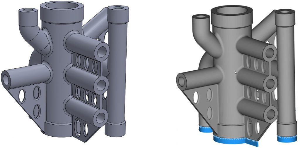
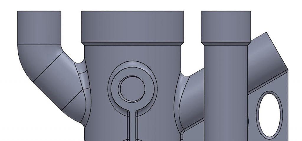
The functionality of the manifold was also improved using the DfAM process. On the original design, the positions of the inlet and outlet ports were determined by the easiest direction from which the holes could be drilled, rather than where they would be most suitable for use or assembly. On the redesigned version, the outlet ports were moved to the top surface and only the inlet remained at the bottom surface. This greatly reduced the overall volume required to install the manifold in the machine. Fig. 2 shows the redesigned manifold before support removal, Fig. 3 shows the manifold after support removal and Fig. 4 shows the completed manifold.
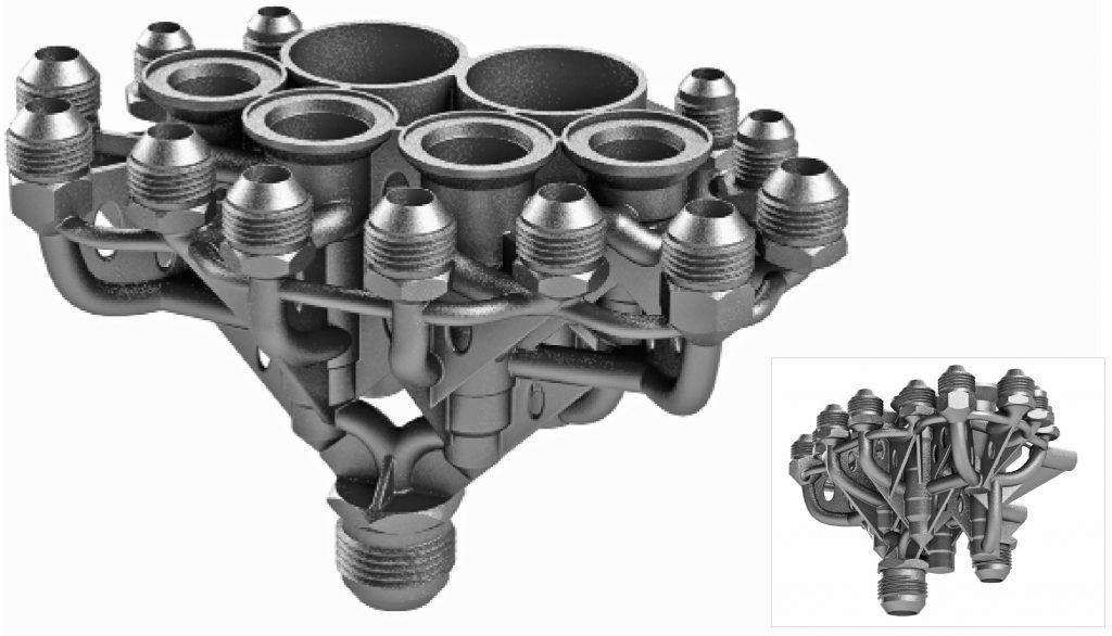
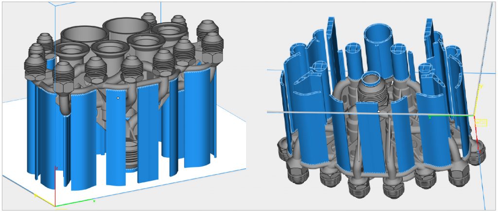
Atlas Copco’s redesigned manifold required minimal amounts of support material (Fig. 5). Also, the required support material was in easy-to-access locations, making it relatively straightforward to remove. After being redesigned for metal AM, the manifold’s weight dropped from 14.6 kg to 1.3 kg – a weight reduction of more than 90%.
Understanding the thought processes used through a simplified design
It is important to consider the overall thought process employed in the redesign of this manifold. One way to examine it is through the step-by-step design of a simple generic manifold made from a 100 mm3 block of steel (Fig. 6).
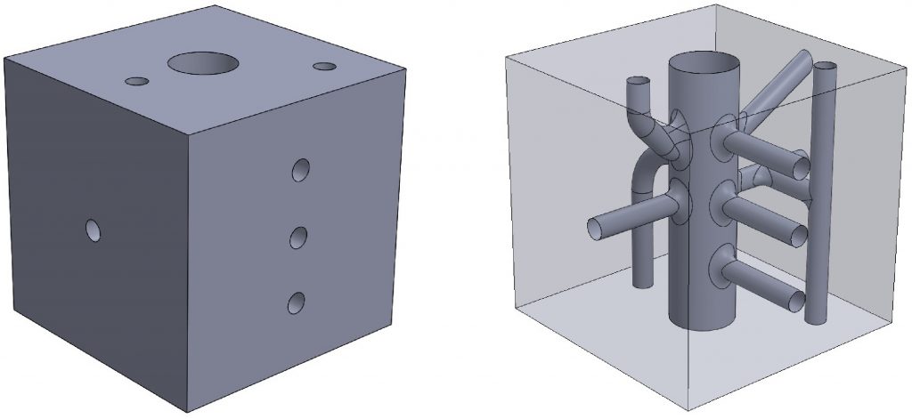
The process begins with simplifying the original block design by eliminating all drilled holes that are normally blocked by plugs. These holes serve no functional purpose other than to allow the creation of internal channels. The goal is to produce the simplest representation of the block manifold with the actual channels for transporting hydraulic fluid. It can also be useful, at this stage, to add fillets to smooth the flow of fluid, compared to the original straight holes.

Reducing material usage
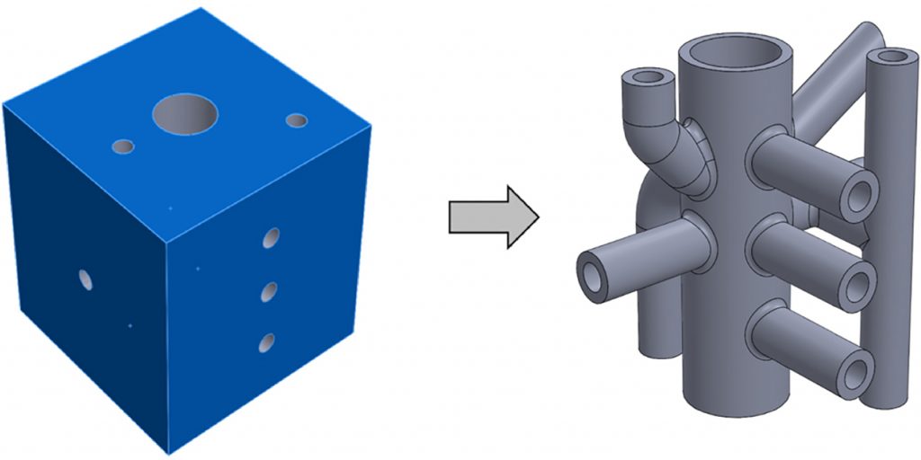
Once the block design has been suitably simplified, the next step is to remove the excess material of the cube to leave only the pipes that form the manifold channels. Most CAD software products have a shell function that removes everything except for a shell of specified wall thickness; in this case, the six outer faces of the cube were selected to be removed, leaving only the internal channel structure, with a wall thickness of 2 mm (Fig. 7).
Using the shelled version, it is much easier to visualise the overall manifold design. This in turn makes it easier to determine whether, and how, the part’s functionality could be improved. In this case, one improvement might be to modify the horizontal channels to include an upwards vertical bend. If so, the easiest option may be to return to and modify the original block design, then redo the shell function. Alternatively, supposing the design is as functionally sound as possible, the next step would be to examine the design from the point of view of AM optimisation. Note also that if the sole purpose of this exercise were to achieve maximum weight reduction, the design would now be complete, because it uses a minimum amount of material.

Part orientation on the build plate
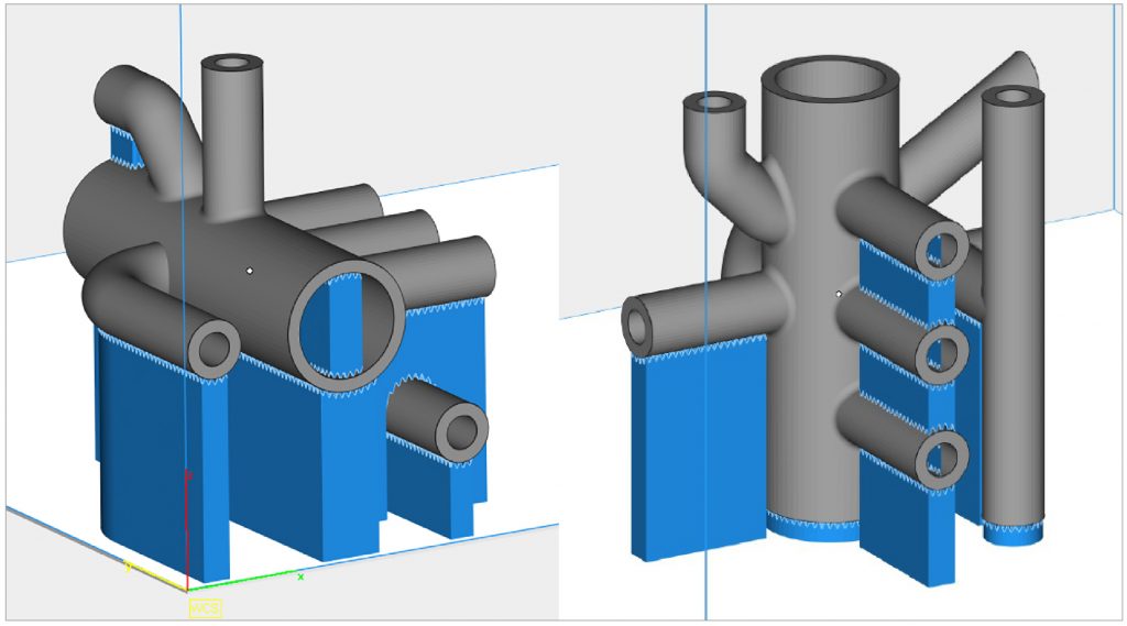
An important factor to consider at this stage of the design is the print orientation, as it will affect most other design decisions. When designing for metal AM, one should always design around the specific orientation in which the part will be printed. This is because part orientation impacts the direction of anisotropy, surface finish, roundness of holes and support material. In this case, one could make the decision to print the part with the large diameter pipe in the vertical orientation. If it were printed with the larger pipe in the horizontal orientation, the larger diameter pipe would become filled with support material, which would be difficult to reach and require additional post-processing, increasing the build time and amount of material used (Fig. 8).
When running the design through software used to generate support structures, such as Magics, we can see that support material is generated between all the horizontal pipes. In the orientation at which the larger diameter pipe is horizontal, support material is generated inside this pipe.
Both print orientations necessitate the removal of support material after printing and both will require surface treatment to improve the finish at the points where the support material makes contact with the part. The print orientation at which the large diameter pipe is horizontal would make it difficult to remove the support from inside the pipe. The better print orientation, therefore, is with the large pipe positioned vertically.

Alternatives to support structures
A design option worth considering is to add a thin wall under each of the horizontal channels to entirely eliminate the need for support material. The idea is that the added wall becomes the support, as well as a permanent feature of the part. In Fig. 9, the bottom walls are chamfered at 45° to eliminate the need for support material. Oval holes in the walls are instead used to reduce weight and eliminate the need for support material inside the holes. The result is a design in which support material is only necessary to attach the bottom of the part to the build plate.
The support walls also provide the functional benefit of added rigidity. These walls will counteract some of the forces generated when fastening the pipes to the manifold and thus help to minimise the risk of damage.
Compared to alternatives, the design in Fig. 9 would require minimal work to remove support material. After using wire EDM or sawing to remove the part from the build plate, a quick shot-peening operation may be sufficient to finish the surfaces. The part may also require the tapping of screw threads, so material can be added to accommodate this (Fig. 10).
Conclusion
With DfAM, it is important to consider a number of design rules and guidelines. Among them are minimum wall thicknesses, hole diameters above which support material is required, and the angle beyond which support material is required.
In this example, the horizontal pipes have been carefully sized to include an inner diameter which eliminates the need for support material. This is usually 6-8 mm, depending on the AM system being used. Material has been added where pipes will be tapped for screw threads as a post processing operation. A 45° angle for chamfers has been used to eliminate the need for support material. The weight of the original 100 mm3 block manifold design in steel is 7.1 kg. In contrast, the optimised design weighs only 600 g – a weight reduction of nearly 92%.
It is important that approaches to DfAM must be taken consciously. The results are only as good as the decisions made about the strategies used to minimise the need for post-processing. This is clearly demonstrated in the Atlas Copco manifold example. By reducing its weight, making it easier to manufacture and improving its functionality through the use of DfAM, the value of the part was substantially increased.
Authors
Olaf Diegel and Terry Wohlers Wohlers Associates, Inc.
Fort Collins
Colorado 80525
USA

LAST MONTH’S MOST-READ ARTICLES


