


CFD simulation for metal Additive Manufacturing: Applications in laser- and sinter-based processes
Computational Fluid Dynamics (CFD) is widely applied to solve a broad range of research and engineering problems, from aerodynamics to engine combustion and microfluidics. In this article, Pareekshith Allu, Senior CFD Engineer at Flow Science, Inc, explains how CFD can also be used to improve laser- and non-laser-based metal Additive Manufacturing processes, including Laser Beam Powder Bed Fusion (PBF-LB), Directed Energy Deposition (DED), Binder Jetting (BJT) and Material Extrusion (MEX). [First published in Metal AM Vol. 6 No. 4, Winter 2020 | 15 minute read | View on Issuu | Download PDF]
Whether it is the car you drive or the coffee maker you use to brew your morning coffee, chances are you interact every day with a technology that was developed with the help of computational fluid dynamics (CFD). CFD is the study of fluid flow using numerical methods. Since the underlying equations of fluid flow have no analytical solutions, we use computers to solve these equations and simulate fluid interactions in different environments. CFD can be applied to a wide range of research and engineering problems in aerodynamics, engine combustion, water and environmental flows, microfluidics and manufacturing. In this article, I will describe how CFD simulations are used to improve both laser-based and non-laser-based Additive Manufacturing (AM) processes.
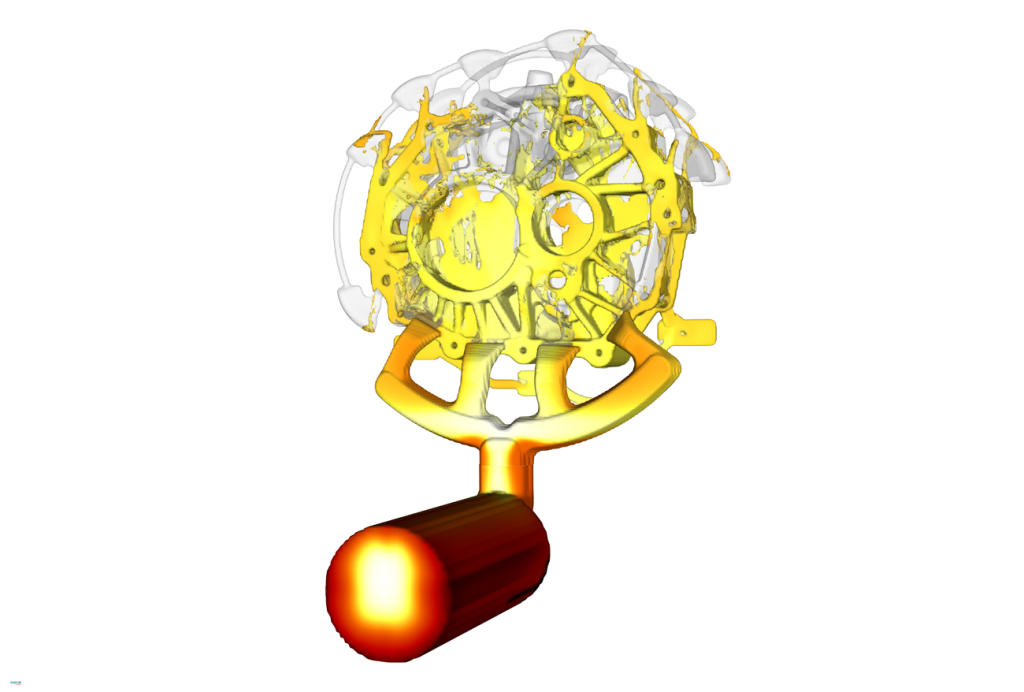
To begin with, it is important to understand the concept of a free surface flow and, thus, potential free surface flow problems unique to CFD. Free surface flow occurs when two fluids with largely different densities share an interface. Picture a river: a free surface exists between the water and the surrounding air, since the gas/liquid interface is free to move and change with time. Free surface flows are ubiquitous – they span civil engineering applications, microfluidics, and are prevalent throughout manufacturing. In metal casting, for example, a free surface exists between molten metal and the air in a mould as it’s filled (Fig. 1); in a laser welding process, a free surface molten pool is formed when a laser beam melts and fuses two metal components or parts together.

Over forty years ago, the founder of Flow Science Inc., Dr C W Hirt, pioneered a computational technique for tracking the evolution of the free surface called the Volume of Fluid (VOF) method – the underlying DNA behind FLOW-3D’s CFD solver. Since then, FLOW-3D’s VOF algorithm, TruVOF®, has been used to simulate fuel sloshing in space shuttle tanks, design spillways for dams, optimise inkjet printers and minimise casting defects. More recently, the company recognised the unique capabilities it could offer in simulating laser welding and AM processes and developed FLOW-3D AM.
Laser Beam Powder Bed Fusion
In the Laser Beam Powder Bed Fusion (PBF-LB) process, a part is manufactured layer by layer. First, powder is spread onto a build plate and a laser beam then melts and fuses the powder in a specific pattern. Then, another layer of powder is spread onto the initial layer and a laser beam melts the new layer, fusing the two layers together. This process is repeated until a part is fully built. There are several aspects of the PBF-LB process that can be better understood and optimised through CFD simulations. For example, using a discrete element method (DEM), it is possible to simulate the powder spreading process in detail. A DEM simulation accounts for particle dynamics, particle collisions and geometry effects. In Fig. 3, you can see how the formation of a packed powder bed can be modelled.
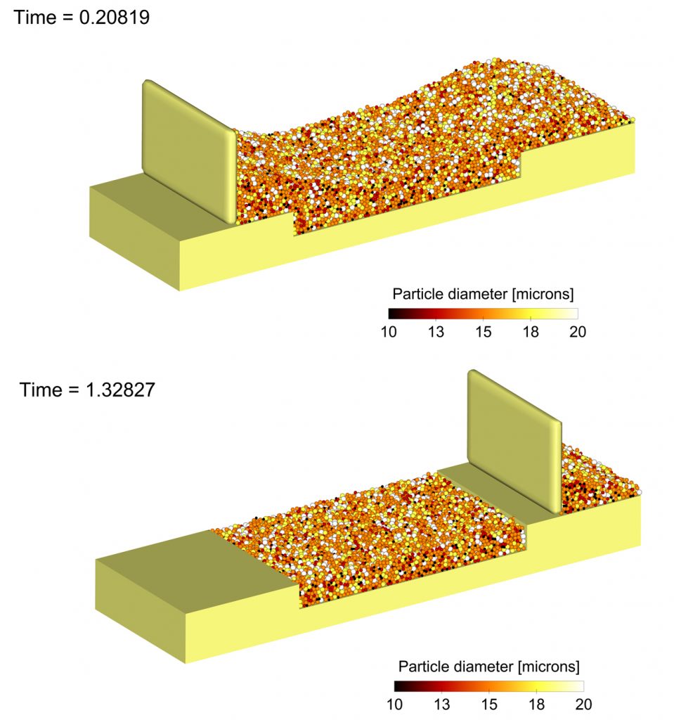
Strictly speaking, DEM is not CFD. However these micro-scale simulations operate at a similar spatial resolution to CFD simulations of the melt pool and provide an important input for modelling the laser beam’s interaction with the powder bed and subsequent melt pool formation. Through DEM, it is possible to optimise powder size distribution, recoater blade dimensions and recoater blade speed to obtain an ideal bed compaction; any speeding up that can be achieved during powder spreading directly translates into faster build rates. Additionally, factors such as the existence of moisture, friction coefficients and non-sphericity of particles can be incorporated into DEM simulations to better understand powder spreading and compaction.
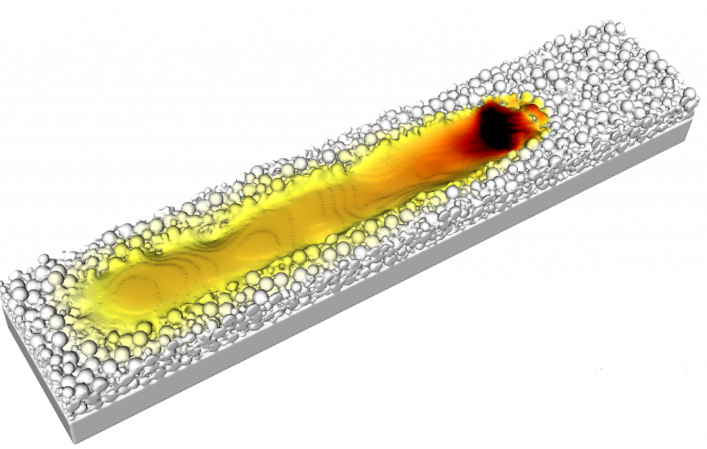
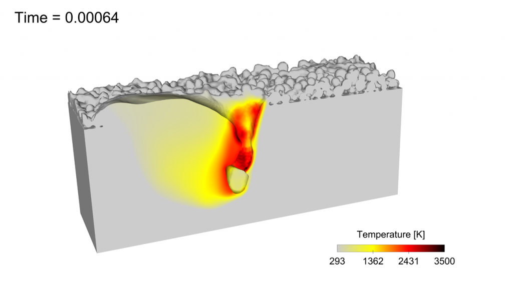
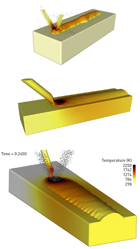
Once the powder bed is generated in a DEM simulation, it is extracted as an STL file. The next step is simulating the laser melting process using CFD. Here, we model the interaction of the laser beam and the particle bed. To capture this process accurately, the relevant physics includes viscous flows, laser reflect-ions within the melt pool (through ray tracing), heat transfer, solidification, phase change and vaporisation, recoil pressure, shield gas pressure and surface tension. Clearly, there is a lot that needs to be incorporated along with the VOF method to accurately simulate this complex process (Figs. 4, 5). Once the melt pool track solidifies, DEM can be used to simulate the spreading of a new powder layer on the previous layer. Similarly, laser melting can then be performed on the new powder layer to analyse fusion between subsequent layers and any other defects that can form during a multilayer build.
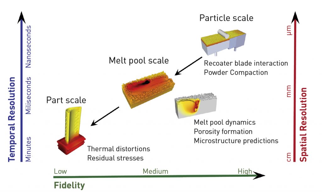
Why are these melt pool models important? The status quo in Additive Manufacturing simulations, especially for PBF-LB and Directed Energy Deposition (DED) processes, is focused on thermomechanical simulations that help with part-scale modelling to predict thermal distortions, residual stresses and the generation of support structures. While these simulations are useful, information about melt pool dynamics and related defects such as balling, keyholing, lack of fusion and porosity are outside the realm of such models. It is important to keep in mind that fluid flow, heat transfer and surface tension within the melt pool also affect thermal gradients and cooling rates, which in turn influence microstructure evolution. Fig. 6 shows the various scales at play in an AM process.
Process parameters such as laser power and speed, scan path, hatch spacing, powder size distribution and powder bed packing influence the AM build process and the mechanical properties of the built part. Through CFD modelling, researchers can understand the effects of these process parameters on underlying physical phenomena such as melt pool dynamics, phase change, solidification and microstructure evolution. Such numerical models, which are based on a rigorous solution of the conservation equations of mass, momentum and energy, can provide useful insights into fluid convection in the melt pool, formation of keyholes, temperature gradients and solidification rates. These insights can then drive development of process windows for newer alloys that take full advantage of the benefits of Additive Manufacturing.

Simulation models can only be trusted when they are validated against experimental data, but gathering real-time information from the melt pool while a build is underway can be challenging. Some research groups have generated ultrafast X-ray synchrotron images and videos of the melt pool as the laser beam melts and fuses powder particles together; these videos show that the process can be quite explosive and dynamic. It is possible to use these data as well as data generated from solidified melt pool tracks, formed by the laser melting of powder particles, to validate the CFD models. This is another advantage of CFD: when validated, CFD models can explain a lot of the underlying phenomena in a PBF-LB process, something which is difficult to analyse in real time.
PBF-LB case studies
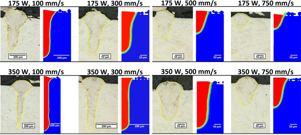
Researchers from Robert Bosch LLC used CFD to investigate the melt pool dynamics of PBF-LB for 316L stainless steel [1]. Through their study they were able to validate the melt pool dimensions and keyhole-induced pore defects obtained in CFD simulations against experimental data (Fig. 7).
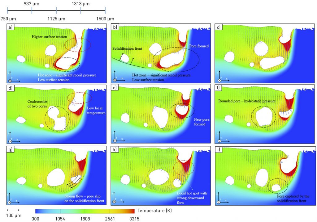
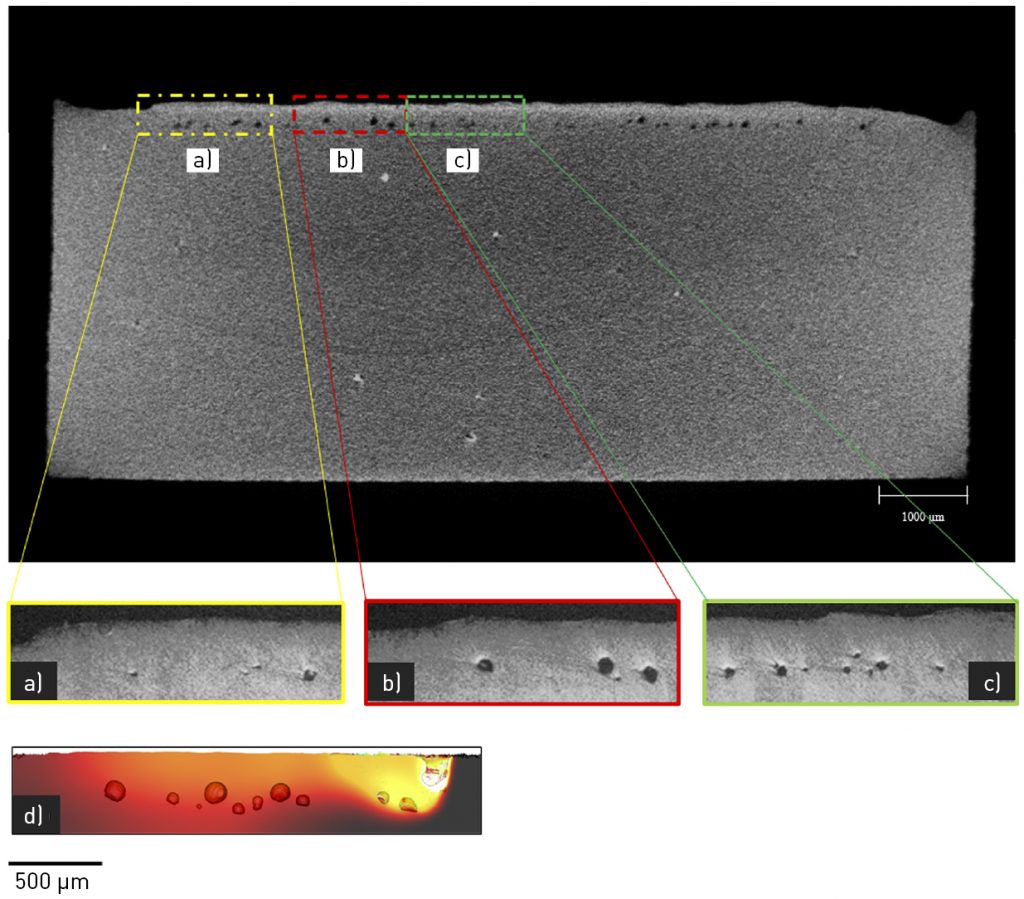
Researchers from the Technical University of Denmark investigated the onset of porosity during keyholing in a PBF-LB process of Ti6Al4V [2]. At high energy densities, a strong recoil pressure is generated on the melt pool surface due to laser/material interactions and phase change due to vaporisation. The coexistence of a strong downward flow and additional heating due to laser reflections within the melt pool leads to the creation and further growth of a keyhole (Fig. 8).
Eventually, this runaway effect results in high temperatures and high recoil pressures at the bottom of the keyhole, and higher surface tension forces in the upper region. The cold zone at the upper region closes to minimise surface energy, which creates an irregularly-shaped pore that detaches from the keyhole. The strong downward flow then pushes the pore into the back of the molten pool, where it rounds off due to hydrostatic pressure and is eventually trapped by the advancing solidification front, resulting in porosity (Fig. 9).
In Fig. 10, the size and location of porosity predicted in the simulations agree with the experimental data. It becomes easier to run simulations with varying process parameters to understand how the melt pool behaves, instead of running multiple experiments and resorting to trial and error. This lets us see how CFD simulations help develop optimal process windows for different alloys used in PBF-LB processes.
Directed Energy Deposition
The above melt pool simulations can be similarly extended to other laser-based processes such as Directed Energy Deposition. In laser-based DED, a wire or a powder source, or sometimes both, feed into a laser beam to build parts layer by layer (Fig. 11). A melt pool similarly forms and can be modelled using CFD. Parameters such as powder or wire feed rate, laser power and scan path can be optimised to ensure a stable melt pool with controlled microstructure evolution.
CFD results can help elucidate surface finish, dimensional accuracy and defect formation in built layers. Moreover, results from a CFD simulation, such as thermal gradients, can be fed into FEA models to determine residual stresses and thermal distortions. Processes like DED also offer the ability to build custom parts with one or more powder and wire materials, aiding in the manufacturing of parts with location-specific material properties. CFD simulations help us understand material mixing within the melt pool, formation of pores and intermetallics and fusion between subsequent layers.

Binder Jetting
CFD simulations can also be beneficial in non-laser-based AM processes. In the Binder Jetting (BJT) process, powder is spread onto the build plate using a roller. A printhead then moves across the powder bed, depositing droplets of binder in a specific pattern. Sometimes the binder is cured by a heat source to better bond the powders together. The print bed is then lowered, and fresh powder is spread onto the build plate, followed by the deposition of additional binder droplets from the printhead. This process is repeated layer by layer to build a ‘green’ part, which is then sintered to achieve better part densification.
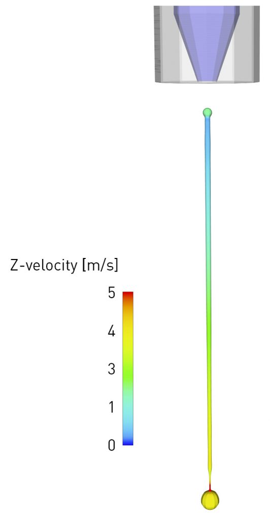
As with the powder laying step in PBF-LB, DEM simulations can be beneficial for studying powder compaction under different roller configurations and powder size distributions. Interestingly, in BJT, the application of CFD can be multi-fold. A typical printhead ejects millions of droplets per second onto the powder bed. CFD can help optimise the volume, shapes, velocities and satellite formation of these droplets by incorporating the effects of nozzle geometries, temperature, bubble energy and material properties such as surface tension and viscosities (Fig. 12).
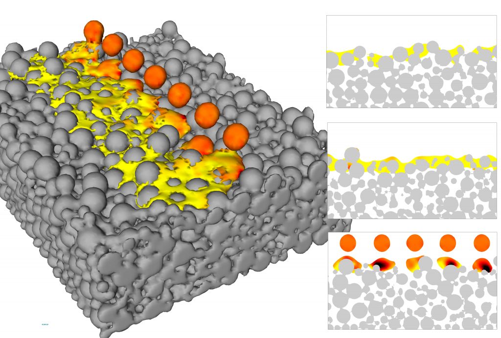
CFD can also help with the study of droplet impact and the subsequent absorption of the binder into the powder bed. In a CFD model, we can consider tens, or even hundreds of spherical droplets impacting the powder bed. This is a good model for understanding binder/powder interactions at the micro-scale, helping optimise and scale up the process. CFD, however, does have its drawbacks in this use: the effects of powder cratering are neglected in this model, and the powder bed is assumed to be fixed in place, a similar assumption that is made in the PBF-LB process. Nevertheless, the model provides valuable insights into binder infiltration, spreading and coalescence within the powder bed. It shows how surface tension and capillary forces dominate and influence the movement of the binder within the inner layers of the powder upon impact. The simulations also show how long the binder takes to spread and infiltrate within the powder layers and how much spacing needs to be implemented between subsequent droplets to ensure optimal coalescence (Fig. 13). Overall, CFD simulations can lead to a better understanding of how different binder materials interact with powder and help optimise the build rate in a Binder Jetting process.
Material Extrusion
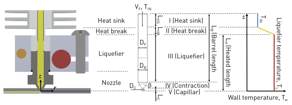
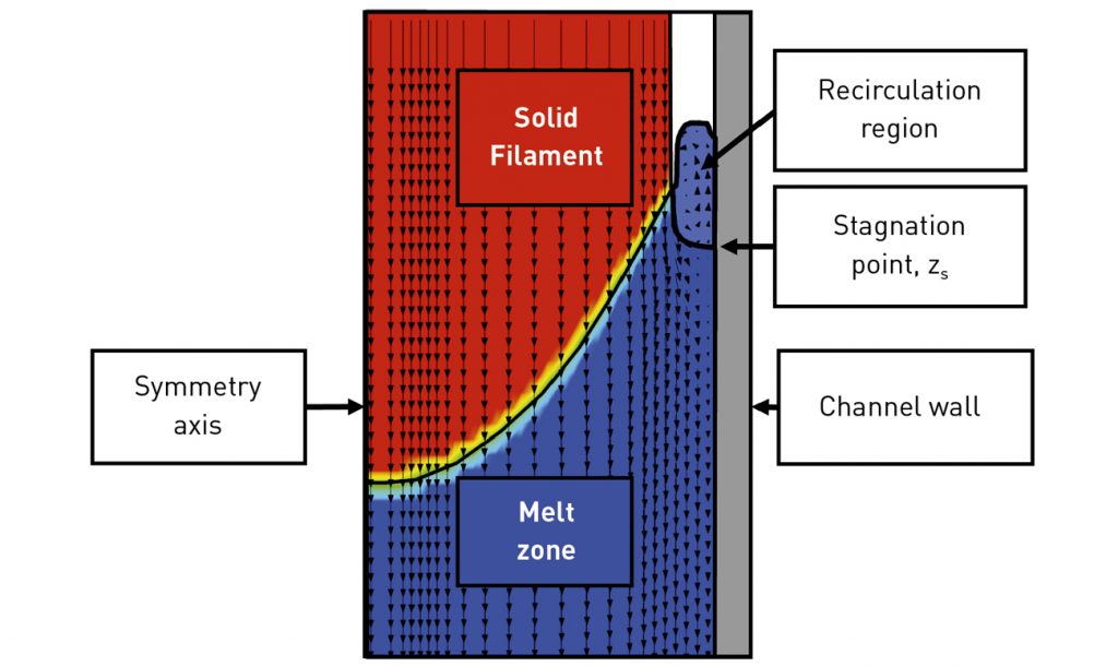
Last but not least, let’s consider Material Extrusion (MEX)-based AM. Take the Fused Filament Fabrication (FFF) process: a polymer-based filament moves through a liquefier that melts the solid filament, which is then extruded through a nozzle onto a build substrate to build a part layer by layer (Fig. 14). Researchers from the Technical University of Denmark have developed a free surface flow CFD model that sheds light on the process [3]. As the solid filament moves through the liquefier, it contacts the chamber walls that melts the filament. The liquefier then fills up with molten filament. A recirculation region of low temperature and high viscosity is formed near the interface of the solid and liquid filament, which is crucial to preventing the backflow of polymer (Fig. 15). Such models can illustrate the effects of conduction, convection and radiation on filament melting and flow.
In an FFF process, CFD is used to study different channel designs that improve heat transfer and maximise the extrusion rate of the filament, ensuring a stable regime. Such models help optimise the pressure drop inside the nozzle, resulting in smaller torque requirements for the stepper motor used to extrude the polymer. This analysis paves the way for faster build rates for FFF and a wider adoption of materials that can be additively manufactured.
Last thoughts
To give you an idea about the simulation times, all the simulations discussed were run on desktop computers that took anywhere from a couple of hours to a day, depending on the physics modelled. By creating a series of simulations, it becomes easier and more economical to develop process windows through modelling instead of having to perform many experiments through trial and error.

I hope you are convinced that CFD simulations are a useful and necessary part of Additive Manufacturing research and development. CFD simulations are by no means stand-alone aspects of the AM simulation workflow. Outputs from CFD simulations can be input into FEA models to analyse thermal distortion and residual stresses, paving the way for a macro-scale analysis. Data from CFD models can also be input into microstructure models to help predict crystal growth and dendrite arm spacing, which in turn can help predict material properties of the built part. Lastly, combining data-driven modelling with physics-based simulations can be quite beneficial in optimising the build parameters for AM.
Being able to bridge the various simulation scales in an AM process to predict how process parameters affect part quality will help AM leverage newer designs and alloys. I hope you are inspired to incorporate CFD into your own AM workflow!
Author
Pareekshith Allu, M.S.
Senior CFD Engineer
Flow Science, Inc.
683 Harkle Rd
Santa Fe, NM 87505
USA
[email protected]
www.flow3d.com/am
References
[1] Cheng, B, Loeber, L, Willeck, H et al. Computational Investigation of Melt Pool Process Dynamics and Pore Formation in Laser Powder Bed Fusion. Journal of Material Engineering and Perform, 28, 6565–6578 (2019). https://doi.org/10.1007/s11665-019-04435-y
[2] Mohamad Bayat, Aditi Thanki, Sankhya Mohanty, et al. Keyhole-induced porosities in Laser-based Powder Bed Fusion (L-PBF) of Ti6Al4V: High-fidelity modelling and experimental validation, Additive Manufacturing, Volume 30 (2019). https://doi.org/10.1016/j.addma.2019.100835
[3] Marcin P. Serdeczny, Raphaël Comminal, Md. Tusher Mollah, David B. Pedersen, Jon Spangenberg, Numerical modeling of the polymer flow through the hot-end in filament-based material extrusion additive manufacturing, Additive Manufacturing, 36; 101454, 2020. doi.org/10.1016/j.addma.2020.101454

LAST MONTH’S MOST-READ ARTICLES


