Additive Manufacturing for spacecraft thermal management: Heat pipes, radiators, and the role of Shape Memory Alloys
As space missions push towards 100 kW nuclear fission systems and megawatt-class propulsion, thermal management is becoming a critical bottleneck. Backed by NASA programmes and working with 3D Systems, researchers at Penn State and Arizona State universities are leveraging metal AM to develop titanium radiator panels with integral heat pipes and NiTi components for self-deploying systems. Tests under simulated orbital conditions showed more than 50% performance gains, proving AM’s potential to cut mass and boost efficiency in spacecraft cooling. [First published in Metal AM Vol. 11 No. 3, Winter 2025 | 20 min read | View on Issuu | Download PDF]

Emerging space mission concepts are set to operate at power levels far beyond anything attempted before. Megawatt-class nuclear electric propulsion (NEP) platforms are being developed to reduce Earth-Mars transit times from roughly 270 to 180 days [1], [2] while NASA’s Fission Surface Power (FSP) programme seeks to deploy compact 10-100 kW nuclear reactors on the Moon to support permanent surface operations [3]. Other high-intensity technologies on the horizon include orbital beamed-energy and laser systems delivering multi-kW outputs [4], as well as large constellations of high-throughput communications satellites now being commercialised by SpaceX, Telesat, OneWeb, and Amazon, among others.
All of these concepts share a critical challenge: how to dissipate the large quantities of waste heat they produce. In space, with no air or fluid to carry heat away, radiation is the only available option. Yet, thermal radiation is relatively weak at the typical operating temperatures of most spacecraft (50-80°C). For example, the International Space Station rejects about 70 kW of heat through 840 m² of panels weighing nearly 1,000 kg. By comparison, a car radiator on Earth can dissipate a similar amount of heat using convection to airflow, requiring only about 1% of the mass and footprint.
Given the current cost of putting mass into orbit (approximately $5,000-20,000 per kg), there is strong pressure to reduce the weight of spacecraft cooling systems.
Emerging solutions such as metal Additive Manufacturing and shape memory alloys (SMAs) are opening the door to lighter, more efficient thermal management designs that could be critical for future missions.
This article explores how Additive Manufacturing can be applied to spacecraft thermal management, focusing on heat pipes, radiator panels, and self-deploying shape memory alloy components. It also considers approaches to testing these technologies under simulated space conditions.

Heat pipes and AM opportunities for spacecraft thermal management
What are heat pipes?
Heat pipes are passive, lightweight heat transfer devices used to cool nearly all modern computers and numerous spacecraft platforms. The most common type operates on the principle of capillary, or ‘wicking’, action (Fig. 3). In this design, a heat pipe is a hollow, closed metal tube internally lined with either a porous metal wick (e.g. sintered powder or mesh) or shallow grooves. A precise charge of working fluid is added, saturating the wick or grooves.
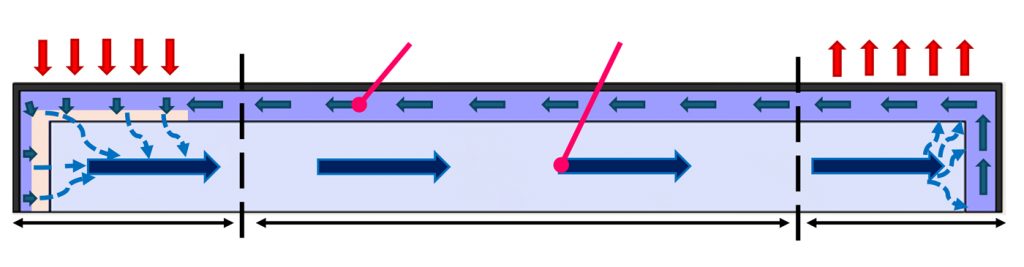
When heated at one end, the liquid evaporates from the wick, providing a local cooling effect, and flows down the heat pipe as vapour. This vapour recondenses into the wick at the cold end, delivering the heat of phase change. As with a candle or scent diffuser, the wick returns liquid to the locally dried evaporator zone through capillary action for continuous operation.
Other fluids are used in speciality applications, such as ammonia and refrigerants in spacecraft exposed to subzero conditions, or alkali metals in nuclear reactor heat pipes operating at ~500-1,000°C. Under the right conditions, heat pipes can enable significant mass savings for space missions as they can achieve extremely high effective thermal conductivities and operate passively, maintenance-free, for decades.

Additive approaches for integrated heat pipes
While heat pipes have been in use for over half a century, conventional manufacturing processes restrict both their performance and design freedom.
For instance, sintered-powder wicks are typically made by heating powder packed between a temporary central mandrel rod and the inside tube wall; this can only be performed for straight tubes. When incorporated into larger thermal assemblies, these pre-manufactured heat pipes must be inserted into prepared housings, introducing additional thermal interface resistances and creating challenges with thermal-expansion mismatches.
With AM, heat pipes can be directly embedded into functional devices, eliminating material interfaces and assembly challenges. This capability enables novel geometries, such as branching heat pipes that can passively transfer heat over large surfaces and volumes, similar to vascular structures found in nature. With support from a NASA Early Stage Innovation grant, we have developed and tested prototype radiator panels based on this concept. Compared with conventional radiator panels incorporating inserted rows of straight heat pipes, such branching networks share flow paths, theoretically offering panel-sized mass reductions of ~50%.
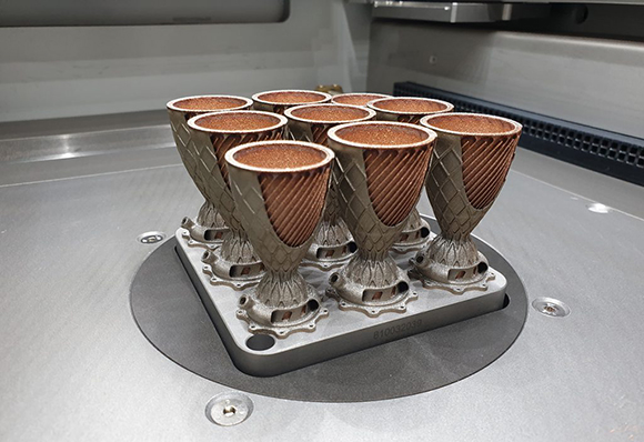
To demonstrate the concept, prototype titanium radiator panels with integral branching heat pipes and internal porous wick structures were made using AM. The main panel sections measured 75 x 125 mm with fin-web thicknesses of 500 µm (Fig. 4). The panels were tested in a cryogenically cooled thermal-vacuum chamber under horizontal (approximately gravity-neutral) conditions to simulate space.

Adapting the approach used for the initial notecard-sized prototypes, scaled-up titanium radiator panels (280 x 220 mm; Fig. 5) were produced. In the larger designs, AM capabilities were leveraged, including lattice structures to improve the stiffness of the thin fin sections and wick-coated pin structures in the evaporator. These pins provide build support during manufacturing while also increasing the effective heat transfer area.

AM also enables precise control of the geometry and pore-scale features of heat pipe wicks, potentially enabling higher-capacity structures than is feasible with conventional Powder Metallurgy or screen insertion. However, AM production of porous structures also represents a subtle and challenging art.
AM of metal wicks with interconnected porosity
The flow performance of porous wicking structures is typically defined by two parameters: permeability (K, in µm²) and pore radius (Rpore, in µm). The capillary pressure that passively drives flow in wicks scales as ΔP∝1/Rpore, but permeability tends to reduce for fine pores as K∝R2pore. Effective wick designs strike a balance between these competing factors, allowing sufficient flow, the ability to lift fluid against gravity, and good thermal conduction through the thin wick layer.
Previous studies have explored the use of AM processes, such as Laser Beam Powder Bed Fusion (PBF-LB), to produce controlled porous wicking structures. While PBF-LB parameters are usually developed to achieve near 100% density, they can be selectively modified in designated regions to form the interconnected porosity required for heat pipe wicks. In one such study, Cameron Noe et al. [5] identified three main strategies (Fig. 6): structured, sintered, and rastered.
![Fig. 6 Strategies for forming interconnected porosity in heat-pipe wicks using Laser Beam Powder Bed Fusion (PBF-LB): structured (top), sintered (middle), and rastered (bottom). Adapted from Noe et al. [5]](http://www.metal-am.com/wp-content/uploads/sites/4/2025/12/f06-2-1024x501.jpg)
The structured wick strategy involves explicitly designing the porosity in Computer Aided Design (CAD) tools. While this approach offers complete design flexibility, it can be challenging to resolve features at relevant sub-millimetre pore scales with standard PBF-LB platforms.
Additionally, pore network geometries must be engineered to facilitate the removal of excess powder post-build. The sintered and rastered strategies rely on modifying the laser process to achieve porosity, instead of representing it in CAD.
Sintered wicks
Sintered wicks are produced by lowering the incident laser energy density below the threshold for full densification, leaving partially fused powder zones with fine, interconnected pores that support capillary action.

Rastered wicks
Rastered wicks are formed by widening the hatch spacing – the distance between successive laser passes – so that pores remain between tracks, similar to a mesh.
Noe et al. carried out an extensive study of high-performance AM wick structures, producing 123 porous specimens by parametrically varying design and processing parameters across the three strategies. Performance was assessed using rate-of-rise experiments, where test cylinders were dipped into fluids such as water or ethanol. The capillary-driven rise of liquid was tracked using visual and infrared imaging alongside continuous weight measurements. From these data, effective permeability and pore radii were derived by fitting the results to theoretical models.
![Fig. 7 2D virtual slices of selected wicks obtained from X-ray microtomography, representing the three wicking strategies. Reproduced from Noe et al. [5]](http://www.metal-am.com/wp-content/uploads/sites/4/2025/12/f07-2-1024x614.jpg)
To better understand the basis for observed capillary properties, three representative samples (one for each strategy) were imaged with X-ray microtomography (Fig. 7). The reconstructed geometries were then applied in computational fluid dynamics (CFD) simulations to directly predict permeability in different flow directions (Fig. 8). Structured wicks showed excellent capillary flow capacity (K/Rpore) in the build direction (z, see Fig. 8d).
![Fig. 8 (a-c) Normalised pressure contours from CFD simulations of capillary flow in the three CT-scanned wick structures: (a) rastered, (b) sintered, and (c) structured. Results are shown for flow along the build direction (z) and transverse direction (x). (d) Summary of predicted capillary flow capacity (K/Rpore) for the three wicks, compared with theoretical values for sintered spheres and reference data from the literature [5]](http://www.metal-am.com/wp-content/uploads/sites/4/2025/12/f08-2-1024x413.jpg)
However, the structured wicks – featuring vertical, lattice-like pore channels aligned with the build direction – performed poorly in the transverse (x-y) directions, suggesting these geometries would need refinement before being used in branching heat-pipe designs.
Sintered wicks were produced with fine pores (Rpore~ 60-90 µm), resulting in high capillary pressures. The resulting randomised structures often contained ‘pinch points’ for flow, visible as sharp pressure jumps in the simulation contours (Fig. 8c). The rastered wicks were found to balance the tradeoffs of the two other strategies, and yield comparable capillary properties (K, Rpore) in both the build and transverse directions. This near-isotropic behaviour makes them well suited for capillary flow networks that branch across multiple directions, such as those demonstrated in the AM heat-pipe radiators of Fig. 5.
![Fig. 9 CT scans and CAD renderings of additively manufactured AlSi10Mg heat pipe specimens with different wick geometries. (a) Baseline plain porous wick. (b) Wick with solid fins to increase the wall-to-wick interface perimeter. (c) Wick with protruding fingers to enlarge the wick-to-vapour interface. (d) Measured temperature drop along the heated evaporator zone, showing up to 70% lower thermal resistance in the modified designs (b, c) [6]](http://www.metal-am.com/wp-content/uploads/sites/4/2025/12/f09-2-1024x360.jpg)
AM also enables novel geometries for heat transfer enhancement in wicking heat pipes. As an example, the rastering process tends to produce relatively highly porous wicks, which facilitate high flow rates but have poor heat transfer through the wick layers. In the investigation of Edward Hieb et al. [6], conductive solid fins were embedded into the evaporator and condenser zones of a demonstration AlSi10Mg heat pipe (Fig. 9). These features reduced overall thermal resistance by up to 70%. These approaches illustrate some of the promising opportunities for engineering and optimisation of functional porous AM structures.
AM of shape memory alloys for spacecraft and beyond
Shape memory alloys are a class of materials that undergo internal lattice reorientation when heated through a controlled temperature range. The most famous SMA is NiTi (nitinol), a near equiatomic alloy of nickel and titanium. When in its lower-temperature martensitic phase, a NiTi specimen can be deformed to a large degree without breaking. When heated to its austenitic phase, the NiTi part recovers toward its original shape, often reversing strains of 5-10%.
In its austenitic phase, NiTi can be repeatedly strained >5% without plastic deformation, a property sometimes termed ‘superelasticity’. This shape recovery property has been demonstrated for the deployment of solar panel arrays and antennas from stowed positions for spacecraft. Here, a small resistance heater can drive actuation, avoiding a larger motor or spring-loaded assembly. NiTi has also been widely adopted for biomedical applications. For example, compressed NiTi stents can be inserted into blood vessels, self-expand to full deployed size as they warm to body temperature, and elastically recover from large deformations in their high temperature phase.

The SMA property of NiTi offers great promise for thermal management of high-power spacecraft. Deployable thermal radiator panels, which expand from stowed configurations to increase heat rejection area, are typically estimated to incur three times the mass of fixed body-mounted panels. Additionally, the hinge mechanisms of deployable radiator panels add large thermal resistances and bottlenecking performance.
SMA radiator panels could theoretically self-deploy from folded (stowed) configurations without hinges, driven passively by the spacecraft’s heat they are rejecting. With AM construction, such SMA radiators could incorporate high-performance heat pipes for effective heat spreading.
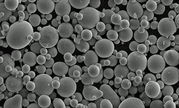
AM of NiTi and SMAs has been a growing area of research for the past decade. Conventionally produced NiTi is only available in specific stock forms (e.g. plate/sheet, wire, tube). The shape recovery, superelasticity, and fatigue resistance properties are optimised through precise mechanical working/drawing and thermal control. For AM, such bulk material is atomised into powder and remelted, impacting some of the original microstructure and forming inactive precipitates.
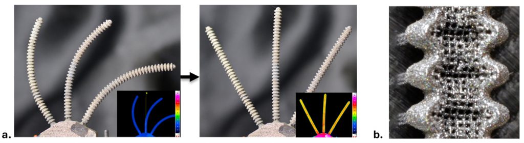
As part of the NASA Small Spacecraft Technology programme (SST), we are developing prototype AM NiTi SMA heat pipes and thermal radiators for CubeSat-sized spacecraft. A rendering of a conceptual design is presented in Fig. 10. Here, radial heat pipes with joined fin sheets would extend outward from a central evaporator hub. In preparation for launch, the assembly could be wound into a tight stowed configuration that would fit in a 1U form-factor: a 10 cm cube that represents a basic unit of compact CubeSats. Upon heating, this pattern would expand to a ~40 cm diameter disk for up to 100 W of heat rejection.

To enable this concept, our team has leveraged PBF-LB capabilities to produce heat pipes with bellows construction (Fig. 11). The convolutions act as hinge points for bending, enabling greater deformation and shape recovery than plain smooth tubes or heat pipes.
Similarly, we have demonstrated AM SMA oscillating heat pipe (OHP) ‘thermal straps’ (Fig. 12). OHPs are passive heat transfer devices comprised of many parallel flow channels, partially filled with working fluid. Boiling vapour bubbles growing in the heated evaporator end of channels (Fig. 12c) displace fluid, returning liquid to the evaporator sections of neighbouring channels. An intrinsic oscillatory flow forms, resulting in effective heat transfer. Such SMA devices could be used as passive actuators for device deployment (Fig. 12d) or mechanically compliant cooling interfaces for gimballed devices.
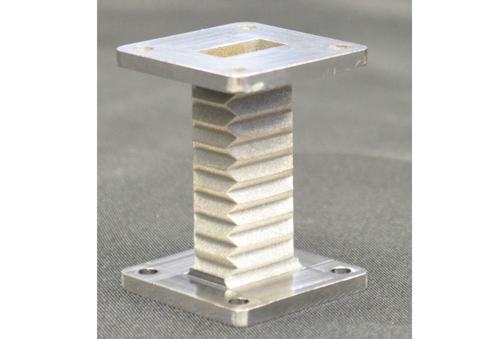
Beyond heat transfer applications, AM of SMA materials enables highly compliant and passively deploying functional devices for applications including biomedical devices and even RF components (Fig. 13).
Testing and design validation for the space environment
Space represents one of the most challenging environments for systems engineering. Spacecraft components must operate maintenance-free for years or decades, subject to vacuum, extreme thermal cycling, and high-energy radiation. In lower orbits, spacecraft experience drag and reactive atomic oxygen. While space systems must be mass optimised to limit flight costs, they must also survive extreme loads and vibrations during launch. Validation of hardware concepts for space operation requires specialised testing facilities.
Penn State’s test facilities
At Penn State, we have developed a space environmental testing suite of thermal-vacuum chambers and associated instrumentation within the Space Propulsion and Environments Lab (SPEL). The equipment comprises an extensive one-of-a-kind suite, capable of space environmental testing for space qualification of subsystems and small satellites, material characterisation, and research on in-space propulsion systems. Current and planned testing capabilities include outgassing assessment, thermal-vacuum, vibration, Atomic Oxygen (AO) degradation, spacecraft charging, plasma interactions, simulated orbital debris impacts (e.g. a high-energy laser is used to simulate micrometeoroid and orbital debris (MMOD) impacts by creating craters and ejecta like traditional grain cannons), solar ultraviolet, and magnetic field interactions. Having all these capabilities in one facility provides a readily accessible hub for space environmental testing of subsystems, payloads, and small satellites.
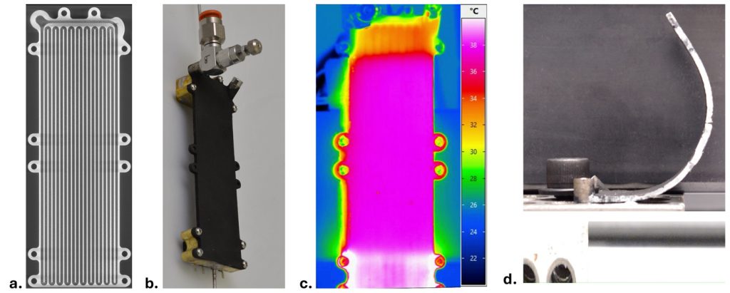
To characterise the performance of these AM heat-pipe radiators in relevant environments, a specialised thermal-vacuum test facility was prepared at Penn State SPEL (Fig. 14). A liquid-nitrogen-cooled aluminium sub-enclosure was installed inside a larger vacuum chamber. A speciality vacuum-rated absorptive coating on the inside of the chamber (Aeroglaze Z306, ~95% IR absorption) simulates the cold space environment. During testing, the facility reaches vacuum levels of 10−5 Torr (~10−8 atm) and wall temperatures near −160°C. Such controlled test conditions are critical because even a slight increase in chamber pressure to 10−4 torr (~10−7 atm) could increase radiator heat transfer rates by ~15% due to convection.
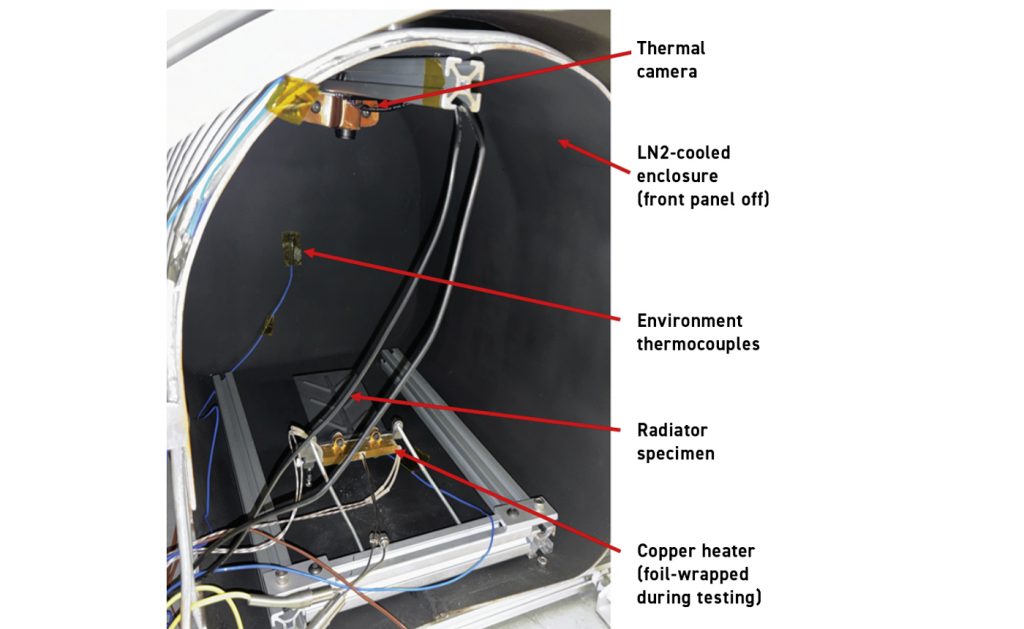
Usage of these test facilities requires careful preparation and component design. For example, speciality low-outgassing and vacuum-rated materials and components had to be adopted, ranging from the thermal paste used for cartridge heaters to the thermal imaging camera. The liquid nitrogen supply is transferred through a custom, explosively welded, stainless-steel to aluminium tube union. This component maintains a gas-tight seal between external stainless-steel connections and the aluminium sub-enclosure. Conventional transitions installed at room temperature could leak at cryogenic temperatures due to the different thermal expansion rates of the materials, impacting vacuum levels. Regular foam- or fibre-based thermal insulation traps gases and can adsorb moisture and oils, which can limit feasible vacuum levels. Instead, reflective metal foil wraps or speciality multi-layer insulation (MLI) blankets are used to isolate components during thermal testing.
This cryogenic vacuum test facility was employed to characterise the titanium and NiTi heat pipe radiator panel prototypes described above. These thermal tests can reveal operational limits and guide design refinement for the heat pipe radiators. For example, the thermal imaging temperature distribution for an initial design of the 75 x125 mm branching radiator panel is shown in Fig. 15a with heat input at 510 K (237°C). The hot spots on the outer sections of the evaporator (bottom of image) indicate dryout.
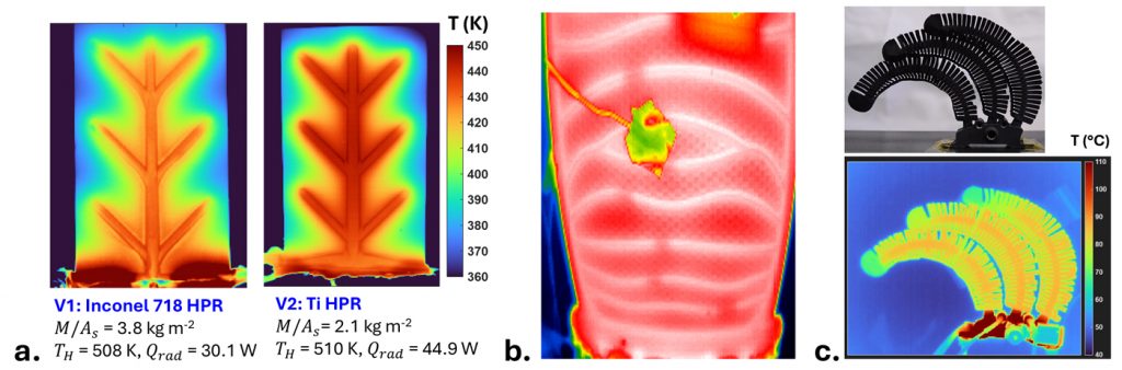
The internal wick layer was not able to continuously resupply liquid from the condenser zones, limiting total heat radiation rate to 30 W. A revised design increased the wick layer cross-section at suspected capillary flow ‘choke points’, resulting in nearly complete wick activation and a 50% increase in heat transfer capacity (to 44.9 ± 2.0 W). Similar cryo-vacuum tests were conducted for the scaled-up titanium 200 x 280 mm branching heat pipe radiator (Fig. 15 b, see photograph in Fig. 5) and NiTi SMA self-deploying heat pipes with bonded conductive copper sheet fins (Fig. 15c). These ‘relevant-environment’ prototype analysis studies represent a key step in design validation and refinement for maturing technology towards spaceflight readiness.

Conclusions and outlook
Additive Manufacturing enables single-step production and embedding of functional devices that can meet the extreme mass and technical requirements of spacecraft systems. Here, it was demonstrated that porous wicking structures can be formed concurrently with solid zones for integral and customised branching heat pipes. This enables thermal management solutions that could not be produced conventionally and avoids resistances and failure points at material interfaces. Similarly, AM enables production of compliant self-actuated components in shape-memory alloys, which are notoriously challenging to machine conventionally. Self-deploying radiator panels can be produced with this approach to meet the unique thermal control needs of high-power-intensity small spacecraft.
Impactful technical performance milestones are being achieved in relevant-environment laboratory studies, but open challenges remain. At the sub-millimetre scale, Laser Beam Powder Bed Fusion can reproduce porous structures similar to those in heat pipe wicks and other Powder Metallurgy devices. However, higher performance designs require finer feature resolution than possible with standard equipment, which is limited by ~100 µm laser track widths and use of 15-50 µm powder feedstock. Higher resolution PBF-LB platforms are being commercialised but incur high costs and have limited build volumes. In a similar sense, AM processing of SMAs offers limited control of the underlying material grain structure.
Conventionally formed SMA devices are mechanically processed and heat-treated to optimise microstructure for shape recovery, fatigue resistance, and hysteresis properties. Ongoing research efforts seek to approach such SMA performance levels with AM [7], [8]. At the macro-scale, the ~1 m build-dimension limit of current PBF-LB systems may be a bottleneck for large-scale assemblies, applications such as radiator arrays for nuclear electric propulsion radiator assemblies, projected at >2,000 m². The scalability of AM processes, such as PBF-LB, is uncertain. Addressing such questions will help define the prospects of Additive Manufacturing in spacecraft thermal technologies.
Acknowledgements
The authors wish to acknowledge generous support from the NASA Space Technology Mission Directorate through the Early-Stage Innovations (Grant 80NSSC22K0260) and Small Spacecraft Technology (Grant 80NSSC23M0234) programmes. This work was also supported, in part, by the Center for Innovative Material Process through Direct Digital Deposition (CIMP-3D) at Penn State University.
Authors
Tatiana El Dannaoui¹, Tome Guenka¹, Dhruv Bhate², Sven Bilén¹, Ryan Overdorff³, Michael Shepard³, and Alexander Rattner¹*
¹ The Pennsylvania State University, University Park, PA 16802, USA
² Arizona State University, Tempe, AZ 85281, USA
³ 3D Systems, USA
*Corresponding Author: [email protected]
References
[1] Mason, Lee, et al., ‘Nuclear power concepts and development strategies for high-power electric propulsion missions to Mars’, Nuclear Technology, vol. 208, sup1, pp. S52-S66, 2022. doi: 10.1080/00295450.2022.2045180
[2] Peakman, Aiden and Lindley, Ben. ‘A review of nuclear electric fission space reactor technologies for achieving high-power output and operating with HALEU fuel’, Progress in Nuclear Energy, vol. 163, 2023. doi: 10.1016/j.pnucene.2023.104815
[3] Choi, Su-Jin and Choi, Morgan, ‘Time-optimal Earth-Mars transfer using nuclear electric propulsion’, Nuclear Engineering and Technology, vol. 57, no. 10, 2025. doi: 10.1016/j.net.2025.103685
[4] Rodenbeck, Christopher, et al., ‘Terrestrial microwave power beaming’, IEEE Journal of Microwaves, vol. 2, no. 1, pp. 28-43, 2022. doi: 10.1109/JMW.2021.3130765
[5] Noe, Cameron, et al., ‘Structured, sintered, and rastered strategies for fluid wicking in additively manufactured heat pipes’, Additive Manufacturing, vol. 99, 2025. doi: 10.1016/j.addma.2025.104669
[6] Hieb, Edward, et al., ‘Experimental characterisation of additively manufactured heat pipes with enhanced evaporator and condenser sections’, Proceedings of the Thermal and Fluids Engineering Conference, Washington, DC, USA, 2025. [Conference paper]
[7] Hamilton, Reginald F, et al., ‘Multi-scale shape memory effect recovery in NiTi alloys additive manufactured by selective laser melting and laser directed energy deposition’, Journal of Materials Processing Technology, vol. 250, pp. 55-64, 2017. doi: 10.1016/j.jmatprotec.2017.06.027
[8] Benafan, Othmane, et al., ‘Additive manufacturing of high-temperature shape memory alloys’, Additive Manufacturing of Shape Memory Materials, 2025, pp. 119-158. doi: 10.1016/B978-0-443-29594-2.00009-2
LAST MONTH’S MOST-READ ARTICLES