


Modelling the mechanical behaviour of additively manufactured cellular structures
One of the most promising aspects of Additive Manufacturing is the design freedom it enables. One manifestation of this design freedom lies in our ability to manufacture cellular structures such as lattices and honeycombs. Implementing cellular structures with AM, however, poses a range of design and manufacturing challenges. In this article Dr Dhruv Bhate, from Phoenix Analysis & Design Technologies, Inc. (PADT), focuses on a key area connecting design and manufacturing to final part implementation – the mechanical behaviour of these structures and the challenges and approaches to developing a reliable way to predict it. [First published in Metal AM Vol. 2 No. 4, Winter 2016 | 25 minute read | View on Issuu | Download PDF]
It is now well appreciated that, within the several design possibilities enabled by metal Additive Manufacturing, cellular structures such as honeycombs and lattices are a particularly exciting research frontier. Cellular structures offer advantages that cannot be easily availed of from homogeneous structures. The better known examples of these advantages, particularly in the aerospace and transportation industries, include increasing stiffness-to-weight ratios, energy absorption and thermal performance. Medical implants also stand to benefit from improved bone integration and the ability to tailor mechanical properties spatially that come with the use of cellular geometries.
These advantages are essentially attained by leveraging the fact that cellular materials allow for tuning the allocation of material and space at a finer level than is attainable through traditional homogeneous structures and at a more accessible level of scale than at the microstructural level. While these advantages have been exploited even before AM arrived on the scene, AM technologies have made it significantly easier to manufacture these structures and explore geometries that were hitherto cost prohibitive or simply not feasible to manufacture.

This article focuses on the modelling aspect of successfully implementing cellular structures using AM technologies. While this is independent of the process used to make these structures, the vast majority of published literature on cellular structures is in metal AM, led by laser-based and electron-beam melting of metal powder. At the outset though, it helps to clarify the big-picture elements that need to come together to enabling production of cellular structures with AM, how modelling interfaces with the other elements and why it is a critical aspect in its own right.
Context: The role of modelling
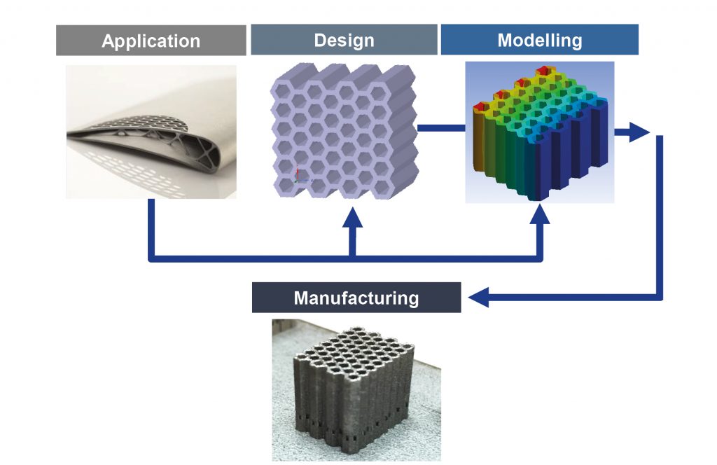
The research and development in AM cellular structures can be broadly classified as belonging to one of four categories: application, design, modelling and manufacturing (Fig. 1). Modelling in this context is the analytical representation of material behaviour, primarily for use in predictive analysis. This is a critical aspect of enabling true simulation-driven design, where the design is the outcome of some objective such as stiffness-to-weight maximisation relative to an allowable stress, for example. From a more abstract point of view, modelling links up design and manufacturing capabilities to the application. Without models that describe cellular structure behaviour, we are left with design tools that make structures that we can manufacture, but with little confidence in their ability to perform the desired function in the end-application. While it is possible to certify components with cellular structures through rigorous testing, valid models and robust simulation together can both drive down qualification costs and also unlock untapped potential that a normal ‘design-manufacture-test’ cycle fails to uncover.
Modelling is thus highly dependent on information from the application and the available design and manufacturing options. A detailed discussion of each of these elements is beyond the scope of this current article, but a brief classification of the available options and tools is provided.

Applications
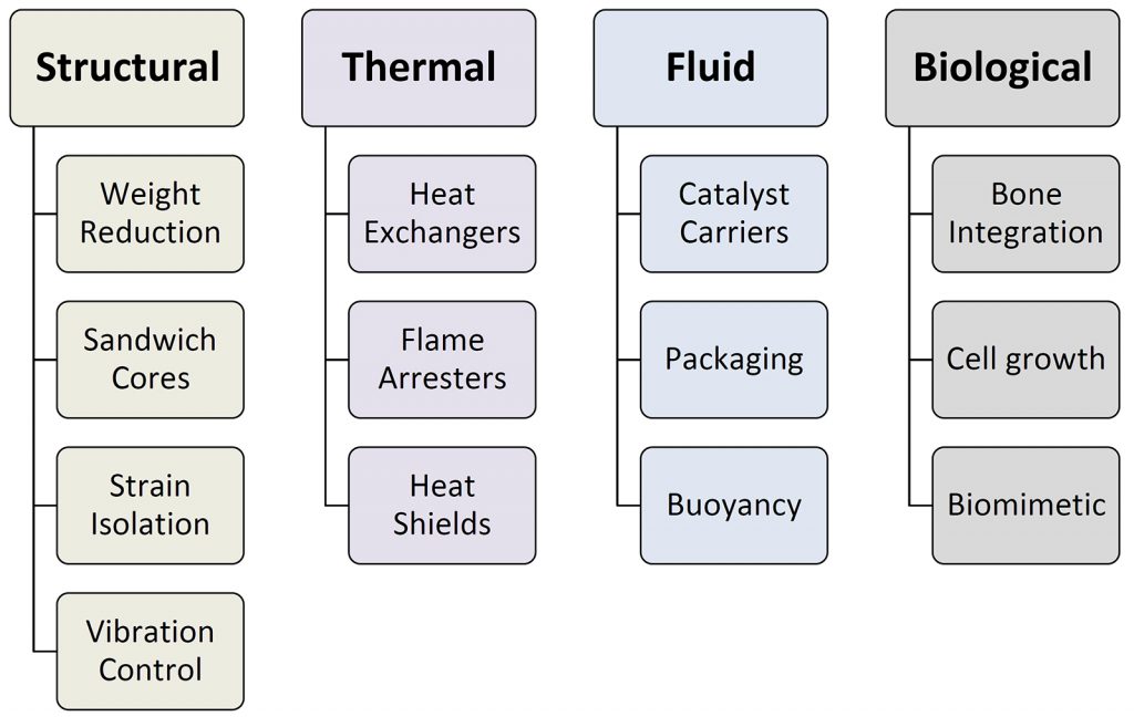
Generally speaking, the applications for cellular structures can be classified into structural, thermal, fluid and biological (Fig. 2). An understanding of the specific advantage being sought by using cellular structures ensures that the model developed is able to incorporate the relevant physics (or chemistry, biology) while also meeting other requirements needed of the part in question that incorporates them. One shared requirement of all manufactured parts is that they retain structural integrity for the intended application. Thus, understanding the mechanical behaviour of cellular structures is a shared area of interest independent of the ultimate reason why cellular structures were preferred to begin with. This is why this article and indeed the majority of the published research focuses on mechanical behaviour.
Design
Several design tools exist today in the form of stand-alone and integrated software solutions. Broadly speaking, these solutions fall into four categories, only two of which rely on analysis and therefore require material models. An approach that is purely geometric is the use of Boolean techniques common to most conventional CAD software, where a cellular structure is first designed and then added to or subtracted from another part. An improvement on this approach is to use what is referred to commonly as ‘infill’. Infilling enables populating a part design with cellular structures and typically enables control on the skin of the part as well. The two approaches that need a material model to be truly effective are topology optimisation based cellular structures and generative approaches. The former solves a topology optimisation problem, but, instead of allocating only material and space as is done conventionally, material densities can now be replaced with cells having equivalent density. Generative approaches, on the other hand, typically begin by defining nodes in space and building connections between nodes in response to an imposed problem, adjusting their thicknesses and distances through a combination of user-provided and analysis driven inputs.

Manufacturing
As mentioned previously, the majority of published literature in cellular structures with AM is in metals. In fact, in a recently conducted literature review of about fifty published papers on cellular structures and AM, it was found by the author that about 80% of these papers involved metal AM, the majority of them with laser-based powder bed fusion as the method of choice. The manufacturing process and material in question together are key inputs for modelling. Additionally, independent of the process used, there are three key manufacturing constraints that need to be considered:
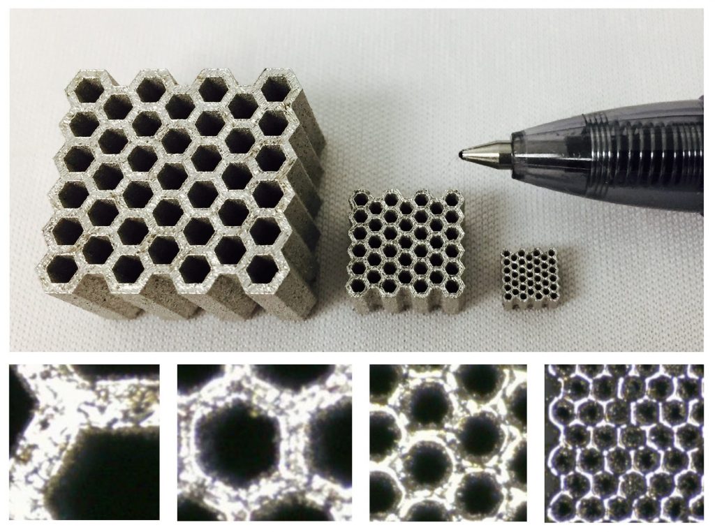
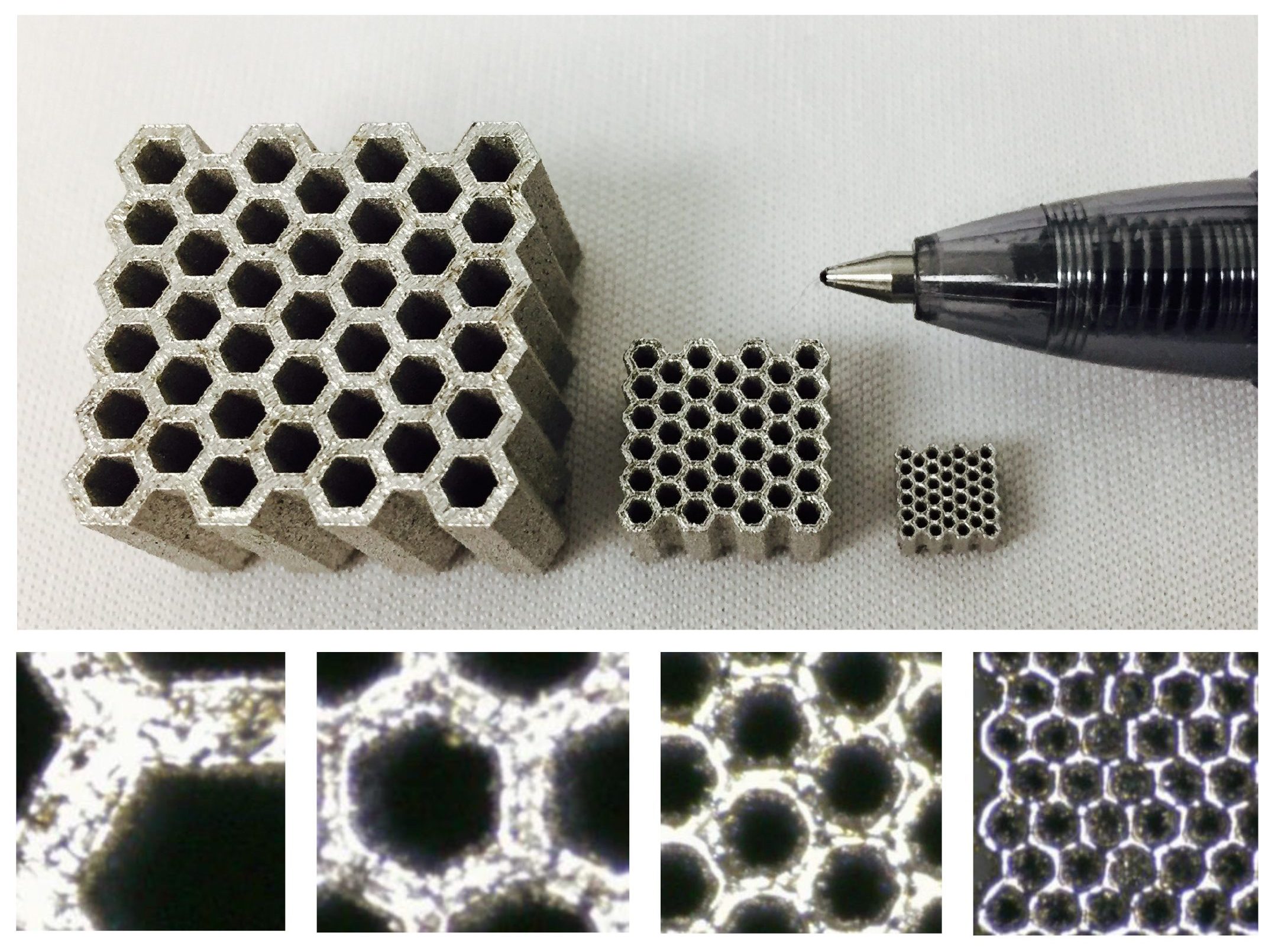
- Minimum feature size: In the context of cellular structures, this refers both to the minimum thickness of the wall or strut and the minimum void volume that can be resolved within the members (Fig. 3). For powder bed fusion metal AM processes, the thinnest walls and struts that can be manufactured are typically in the range of 150-500 µm. The smallest volume that can be encapsulated varies strongly as a function of the specific cell in question.
- Support strategies: Most metal AM processes will require some form of support for mechanical and/or thermal reasons. With cellular structures, the structures must themselves provide this support.
- Accessibility: Another consideration is accessing both trapped powder and the structures themselves (for any finishing operations) – this may drive the need to provide escape holes for the powder, in the case of the former, and, in the case of the latter, defining minimum cell size not on the basis of the machine capability, but on the ability of the finishing agent to access the interior cells.
Classification of cellular structures
From a designer’s perspective, the first step in implementing cellular structures in Additive Manufacturing is selecting the appropriate unit cell. The unit cell is selected based on the performance desired of it as well as the manufacturability of the cells. Seminal texts in the area of cellular solids and materials selection classify unit cells in the following four categories [2, 3].

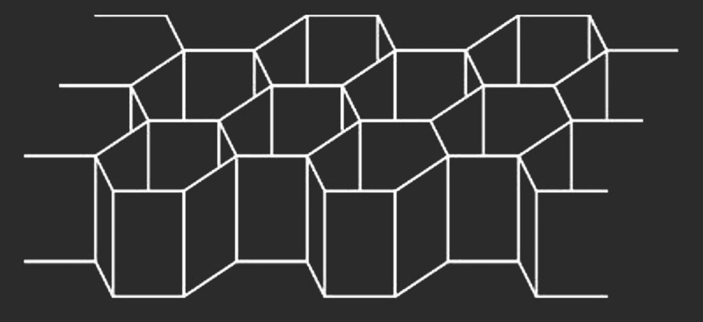
Honeycomb
Honeycombs are prismatic, 2-dimensional cellular designs extruded in the 3rd dimension, like the well-known hexagonal honeycomb (Fig. 4). All cross-sections through the 3rd dimension are thus identical, making honeycombs somewhat easy to model mathematically. Though the hexagonal honeycomb is the most easily identifiable, the term applies to all designs that have this prismatic property, including square and triangular honeycombs. Honeycombs have strong anisotropy in the 3rd dimension. In fact, the modulus of regular hexagonal honeycombs is transversely isotropic; equal in all directions in the plane but very different out-of-plane. The 2D nature of honeycomb structures means that their use is beneficial when the environmental conditions are predictable and the honeycomb design can be oriented in such a way as to extract maximum benefit. Examples of this include crash panels in the automotive industry, sandwich panels in construction and automotive radiator grilles. In all these cases, the direction of the environmental stimulus is known, whether it be the mechanical load or fluid flow.
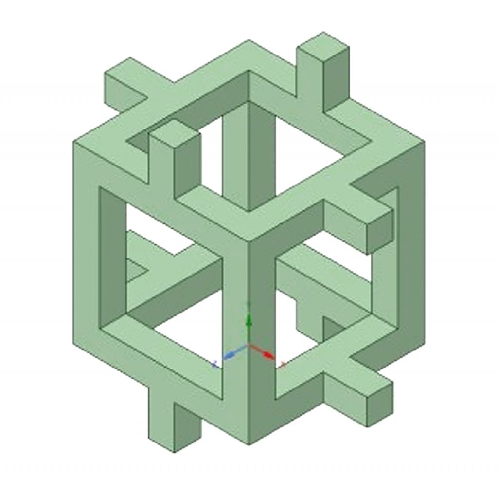
Open-cell foam
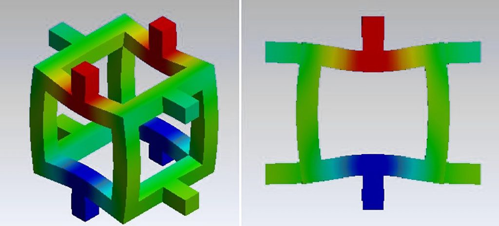
Freeing up the prismatic requirement on the honeycomb enables a fully 3-dimensional open-cell foam design as shown in one representation of a unit cell in Fig. 5. Typically, open-cell foams are bending-dominated, distinguishing them from stretch-dominated lattices, which are discussed in more detail in a following section on lattices. Unlike the honeycomb, open cell foam designs are more useful when the environmental stimulus (stress, flow, heat) is not as predictable and unidirectional. The bending-dominated mechanism of deformation (Fig. 6) makes open-cell foams ideal for energy absorption – stretch dominated structures tend to be stiffer in comparison. As a result of this, applications that require energy absorption such as mattresses and crumple zones in complex structures benefit from open cell foam designs. The interconnectivity of open-cell foams also makes them a candidate for applications requiring fluid flow through the structure.
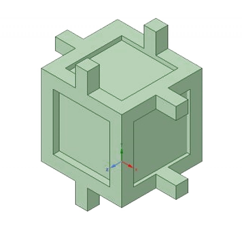
Closed-cell foam
As the name suggests, closed cell foams are open-cell foams with enclosed cells, such as the representation shown in Fig. 7. This typically involves a membrane-like structure that may be of varying thickness from the strut-like structures, although this is not necessary. Closed-cell foams arise in a lot of organic processes commonly found in nature. In man-made entities they are commonly found in the food industry (bread, chocolate) and in engineering applications where the enclosed cell is filled with some fluid (like air in bubble wrap, foam for bicycle helmets and fragile packaging). The primary benefit of closed cell foams is the ability to encapsulate a fluid of different properties for compressive resilience. From a structural standpoint, while the membrane is a load-bearing part of the structure under certain loads, the additional material and manufacturing burden can be hard to justify. Within the AM context, this is a key area of interest for those exploring 3D printing of food products, for example, but may also have value for biomimetic applications with metal AM.
Lattice
Lattices are, in appearance, very similar to open cell foams, but differ in that lattice member deformation is stretch – as opposed to bending – dominated. This is important since, for the same material allocation, structures tend to be stiffer in tension and/or compression compared to bending. By contrast, bending-dominated structures typically absorb more energy and are more compliant. So the question is – when does an open cell foam become stretch dominated and, therefore, a lattice? Fortunately, there is an equation called Maxwell’s stability criterion that addresses just this issue. The criterion involves the computation of a metric M for a lattice-like structure with b struts and j joints as follows:
- In 2D structures: M = b – 2j + 3
- In 3D structures: M = b – 3j + 6
With Maxwell’s criterion and assuming the joints are locked (and not pinned), if M < 0, we get a structure that is bending-dominated. If M ³ 0, the structure is stretch dominated. The former constitutes an open-cell foam, the latter a lattice. There are several approaches to establishing the appropriateness of a lattice design for structural applications (connectivity, static and kinematic determinism etc.) and how they are applied to periodic structures and space frames. For a periodic structure to be truly space-filling, as is needed for AM applications, there is no simple rigid polyhedron that can accomplish this. A combination of polyhedra, such as an octahedron and tetrahedron that together make up an octet truss, are needed to generate true space filling rigid structures [4, 5].
Lattices are the most common cellular solid studied in AM. This is primarily on account of their strong structural performance in applications where high stiffness-to-weight ratio is desired (such as aerospace), or where stiffness modulation is important (such as in medical implants). However, it is important to realise that there are other cellular representations that have a range of other benefits that lattice designs cannot provide. Generally speaking, the following guidelines apply:
- Honeycomb structures for predictable, unidirectional loading or flow
- Open cell foams where energy absorption and compliance is important
- Closed cell foams for fluid-filled and hydrostatic applications
- Lattice structures where stiffness and resistance to bending is critical.
Considerations in the modelling of cellular structures
Selecting a particular unit cell design based on the functionality sought is the starting point for a designer. This must then be coupled with a model that describes the performance of that structure, which in turn requires the development of an analytical model and an experimental characterisation protocol that goes along with it. While there are standards for most mechanical testing, the standards for cellular structures are very limited. This is partly on account of the significant challenges associated with developing models for cellular structures, which are presented here.
Complex geometry with non-uniform local conditions
The first and most obvious challenge with cellular structures is that they are not fully-dense homogeneous materials with relatively predictable responses governed by straightforward analytical expressions. Consider a dogbone-shaped specimen of solid material under tension: its stress-strain response can be described fairly well using continuum expressions that do not account for geometrical features beyond the size of the dogbone (area and length for stress and strain computations respectively). However, as shown in Fig. 8, such is not the case for cellular structures, where local stress and strain distributions are non-uniform. Further, they may have variable distributions of bending, stretching and shear in the connecting members that constitute the structure.
Size effects
A size effect is said to be significant when an observed behaviour varies as a function of the size of the sample whose response is being characterised even after normalisation (dividing force by area to obtain stress, for example). For this discussion, size effects are limited to purely mathematical artefacts of the cellular geometry itself, independent of the manufacturing process used to make them. In other words this effect would persist even if the material in the cellular structure was a mathematically precise, homogeneous and isotropic material.
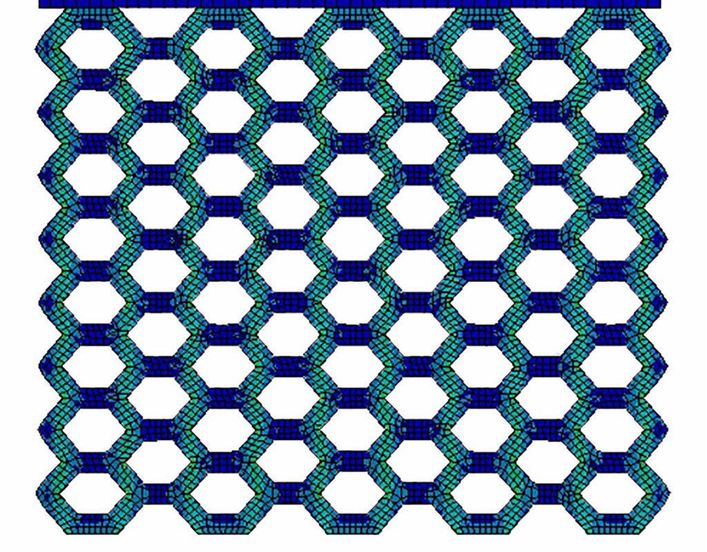
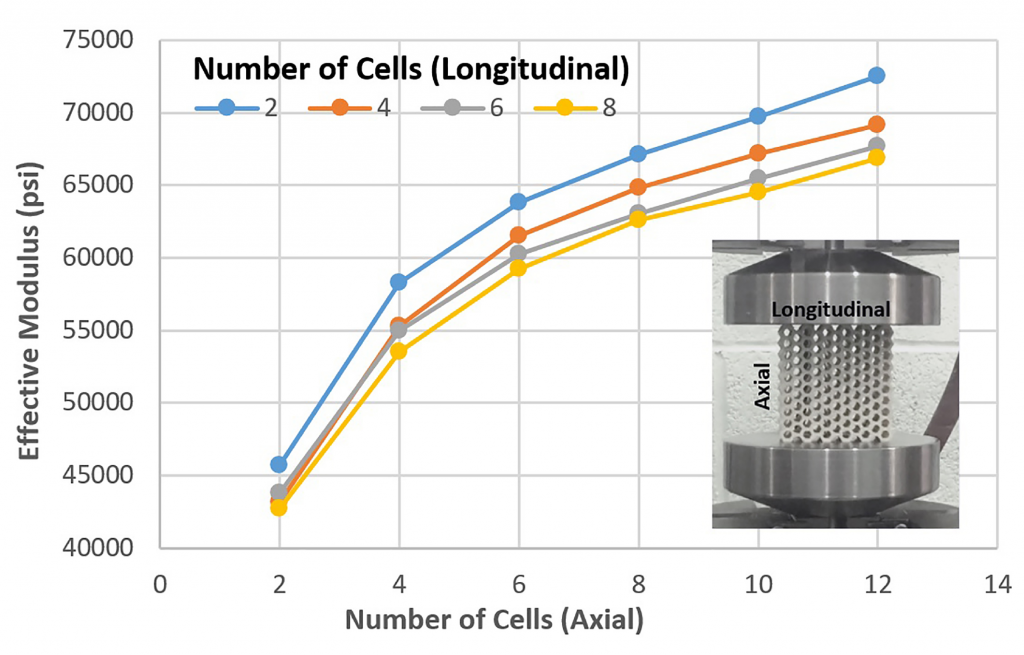
It is common in the field of cellular structure modelling to extract an ‘effective’ property; a property that represents homogenised behaviour without explicitly modelling the cellular detail. This is an elegant concept but introduces some practical challenges in implementation; inherent in the assumption is that this property, modulus for example, is equivalent to a continuum property valid at every material point. The reality is that the extraction of this property is strongly dependent on the number of cells involved in the experimental characterisation process. Consider the experimental data in Fig. 9 for honeycombs in compression, showing that the predicted effective modulus increases with increasing number of cells in the axial direction, but reduces (at a lower rate) for increasing number of cells in the longitudinal direction. The number of cells in a sample being used to extract model data is thus a very significant consideration.
In addition to the number of cells, the actual size of the specimen as an entity can influence the results. For certain dimensions of the specimen being characterised (typically very tall aspect ratios), deformation in the macrostructure can influence what is perceived as cellular behaviour. It is essential to avoid very large aspect ratios since they tend to exacerbate these macrostructural effects.
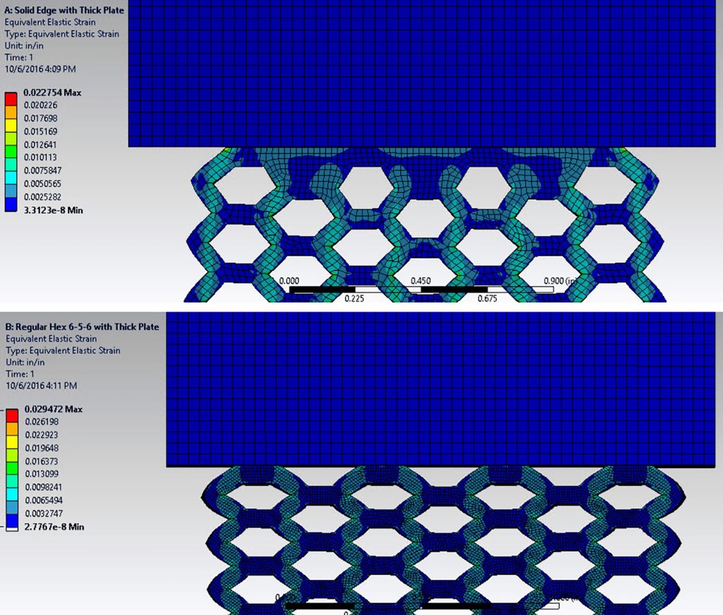
Contact effects
In the compression test, shown in the inset in Fig. 9, there is physical contact between the platens and the specimen that creates a local effect at the top and bottom that is different from the experience of the cells closer to the centre. This is tied to the size effect discussed above, but needs separate consideration for two reasons. Firstly, it raises the question of how best to design the interface for the specimen: should the top and bottom cells terminate in a flat plate, or should the cells extend to the surface of contact (the latter is the case in Fig. 9). Secondly, it raises the question of how best to model the interface, especially if one is seeking to match simulation results to experimentally observed behaviour. Both of these ideas are shown in Fig. 10. This also has implications for product design – how do we characterise and model the lattice-skin interface? As such, independent of addressing size effects, there is a need to account for contact behaviour in characterisation, modelling and analysis.
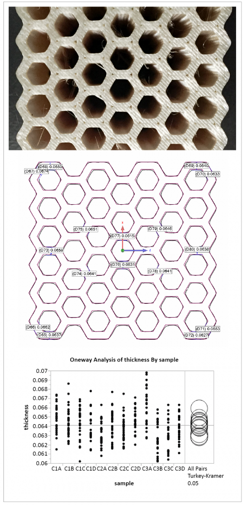
Dimensional tolerances
While all manufacturing processes introduce some error in dimensional tolerances, the error can have a very significant effect for cellular structures. A typical industrial AM process has tolerances of approximately 75 µm (0.003”), whereas cellular structures (micro-lattices in particular) very often are 250-750 µm in thickness, meaning the tolerances on dimensional error can be in the 10% and higher error range for thickness of these members (Fig. 11). Such large errors in thickness can yield a significant error in measured behaviour such as elastic modulus, which often goes by some power to the thickness, amplifying the error. This drives the need for some independent measurement of the manufactured cellular structure; made challenging itself by the need to penetrate the structure for internal measurements. X-ray scanning is a popular, if expensive, approach. However, the modeller then has the challenge of devising an average thickness for analytical calculations and, furthermore, the challenge of representation of geometry in simulation software for efficient analysis.
Mesostructural effects
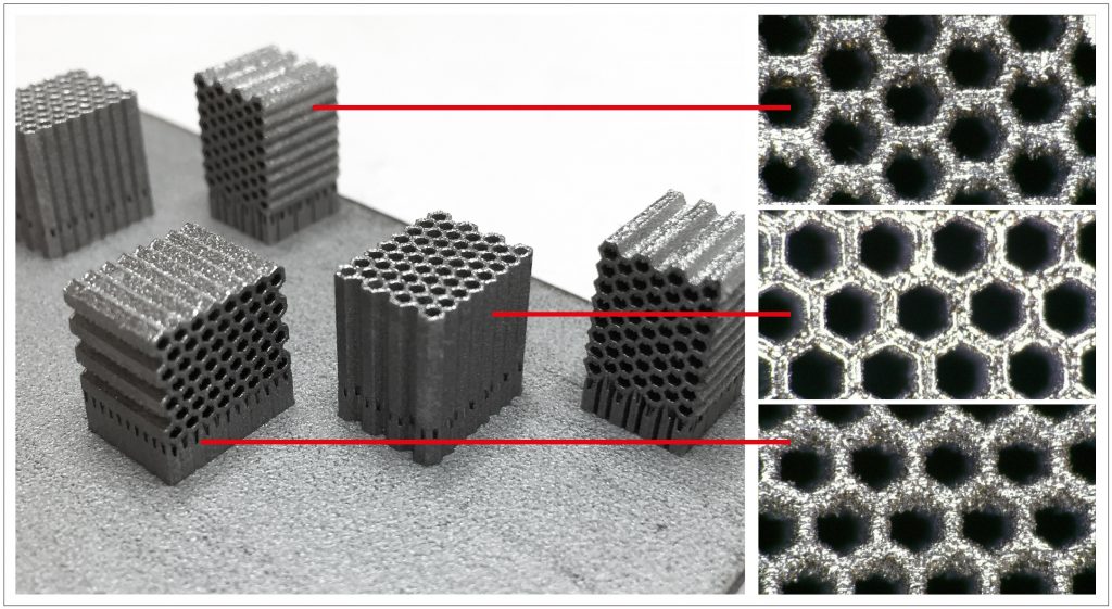
The layer-wise nature of AM introduces a unique set of challenges, chief among which is the resulting sensitivity to orientation, as shown for the laser-based powder bed fusion process in Fig. 12 with standard materials and parameter sets. Overhang surfaces (unsupported) tend to have down-facing surfaces with different morphology compared to up-facing ones. In the context of cellular structures, this is likely to result in different thickness effects depending on direction measured. Thus, orientation and process parameters are variables that need to be comprehended in the modelling of cellular structures, or set as constants for the range of applicability of the model parameters that are derived from a certain set of process conditions.
Modelling approaches
The literature on the AM of cellular structures is vast and growing. While the majority of the focus in this field is on design and process aspects, there is a significant body of work on characterising behaviour for the purposes of developing analytical material models. These approaches fall into three different categories depending on the level of discretisation at which the property is modelled: at the level of each material point, or at the level of the connecting member or, finally, at the level of the cell.
Continuum modelling
The most straightforward approach is to use bulk material properties to represent what is happening to the material at the cellular level [6-9]. This approach does away with the need for any cellular level characterisation and, in so doing, does not have to account for size or contact effects described previously that are artefacts of having to characterise behaviour at the cellular level. However, the assumption that the connecting struts/walls in a cellular structure behave in the same way as the bulk material does can particularly be erroneous for AM processes that can introduce significant size-specific behaviour and large anisotropy. It is important to keep in mind that factors that may not be significant at a bulk level, such as surface roughness, local microstructure or dimensional tolerances, can be very significant when the connecting member is under 1 mm thick, as is often the case for cellular structures in AM. The level of error introduced by a continuum assumption is likely to vary by process: polymeric processes like Fused Deposition Modelling (FDM) are already strongly anisotropic with highly geometry-specific meso-structures and an assumption like this will generate large errors. On the other hand, it is possible that better results may be had for powder based fusion processes used for metal alloys, especially when the connecting members are large enough and the key property being solved for is mechanical stiffness (as opposed to fracture toughness or fatigue life).
Cell level homogenisation
The most common approach in the literature that accounts for cellular behaviour is the use of homogenisation; representing the effective property of the cellular structure without regard to the cellular geometry itself. This approach has significantly lower computational expense associated with its implementation in simulation software. Additionally, it is relatively straightforward to develop a model by fitting a power law to experimental data [10-13] as shown in the equation below, relating the effective modulus E* to the bulk material property Es and their respective densities (r and r s ), by solving for the constants C and n.
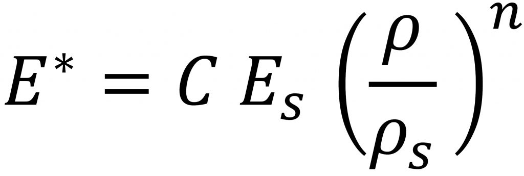
While a homogenisation approach is useful in generating comparative, qualitative data, it has some difficulties in being used as a reliable material model in analysis and simulation. This is first and foremost since the majority of the experiments do not consider size and contact effects. Secondly, even if these were considered, the homogenisation of the cells only works for the specific cell in question (e.g. octet truss or hexagonal honeycomb), so that every new cell type needs to be re-characterised. Finally, the homogenisation of these cells can lose insight into how structures behave in the transition region between different volume fractions, even if each cell type is calibrated at a range of volume fractions. This is likely to be exacerbated for failure modelling.
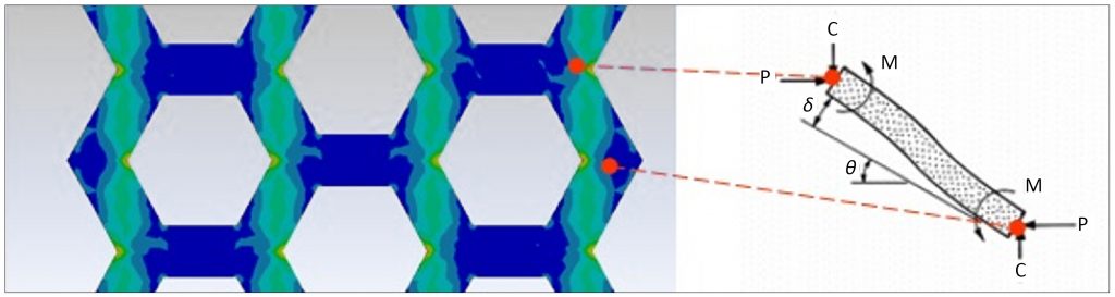
Member modelling
The third approach involves describing behaviour not at each material point or at the level of the cell, but at a level in-between: the connecting member (also referred to as strut or beam) (Fig. 13). This approach has been used by researchers including this author [14-16] by invoking beam theory to first describe what is happening at the level of the member and then using that information to build up to the level of the cells. This approach, while promising, is also beset with some challenges. It requires experimental characterisation at the cellular level, which brings in the previously mentioned challenges. Additionally, from a computational standpoint, the validation of these models typically requires a modelling of the full cellular geometry, which can be prohibitively expensive. Finally, the theory involved in representing member level detail is more complex, makes assumptions of its own (e.g. modelling the ‘fixed’ ends) and it is not proven adequately at this point if this is justified by a significant improvement in the model’s predictability compared to the above two approaches. This approach does have one significant promise. If we are able to accurately describe behaviour at the level of a member, it is a first step towards a truly shape and size independent model that can bridge with ease between, say, an octet truss and an auxetic structure, or different sizes of cells, as well as the transitions between them, thus enabling true freedom to the designer and analyst.
Conclusion
Additive Manufacturing with cellular structures is a justifiably promising field with many examples demonstrated from a software and manufacturing standpoint, as well as some successful applications. However, as this article has attempted to demonstrate, there is a real need for developing models that can allow us to truly leverage cellular structure designs in all additive parts, including those that end up in functionally critical applications. The research in this field, as with most of functional part AM, is relatively immature, especially when compared to the work on software solutions and manufacturing capabilities for cellular structures. More work needs to be done before we can truly unlock the full potential of using cellular structures as just another choice available to designers.
References
[1] Ashby, Evans, Fleck, Gibson, Hutchinson, Wadley, “Metal Foams: A Design Guide,” First Edition, 2000
[2] Ashby, “Materials Selection in Mechanical Design,” Fourth Edition, 2011
[3] Gibson & Ashby, “Cellular Solids: Structure & Properties,” Second Edition, 1997
[4] Deshpande, Ashby, Fleck, “Foam Topology Bending versus Stretching Dominated Architectures,” Acta Materialia 49, 2001
[5] Deshpande, Fleck, Ashby, “Effective properties of the octet-truss lattice material,” Journal of the Mechanics and Physics of Solids, 49, 2001
[6] C. Neff, N. Hopkinson, N.B. Crane, “Selective Laser Sintering of Diamond Lattice Structures: Experimental Results and FEA Model Comparison,” 2015 Solid Freeform Fabrication Symposium
[7] M. Jamshidinia, L. Wang, W. Tong, and R. Kovacevic. “The bio-compatible dental implant designed by using non-stochastic porosity produced by Electron Beam Melting®(EBM),” Journal of Materials Processing Technology 214, no. 8 (2014): 1728-1739
[8] S. Park, D.W. Rosen, C.E. Duty, “Comparing Mechanical and Geometrical Properties of Lattice Structure Fabricated using Electron Beam Melting”, 2014 Solid Freeform Fabrication Symposium
[9] D.M. Correa, T. Klatt, S. Cortes, M. Haberman, D. Kovar, C. Seepersad, “Negative stiffness honeycombs for recoverable shock isolation,” Rapid Prototyping Journal, 2015, 21(2), pp.193-200.
[10] C. Yan, L. Hao, A. Hussein, P. Young, and D. Raymont. “Advanced lightweight 316L stainless steel cellular lattice structures fabricated via selective laser melting,” Materials & Design 55 (2014): 533-541.
[11] S. Didam, B. Eidel, A. Ohrndorf, H.-J. Christ. “Mechanical Analysis of Metallic SLM-Lattices on Small Scales: Finite Element Simulations versus Experiments,” PAMM 15.1 (2015): 189-190.
[12] P. Zhang, J. Toman, Y. Yu, E. Biyikli, M. Kirca, M. Chmielus, and A.C. To. “Efficient design-optimization of variable-density hexagonal cellular structure by Additive Manufacturing: theory and validation,” Journal of Manufacturing Science and Engineering 137, no. 2 (2015): 021004.
[13] M. Mazur, M. Leary, S. Sun, M. Vcelka, D. Shidid, M. Brandt. “Deformation and failure behaviour of Ti-6Al-4V lattice structures manufactured by selective laser melting (SLM),” The International Journal of Advanced Manufacturing Technology 84.5 (2016): 1391-1411.
[13] R. Gümrük, R.A.W. Mines, “Compressive behaviour of stainless steel micro-lattice structures,” International Journal of Mechanical Sciences 68 (2013): 125-139
[14] S. Ahmadi, G. Campoli, S. Amin Yavari, B. Sajadi, R. Wauthle, J. Schrooten, H. Weinans, A. Zadpoor, A. (2014), “Mechanical behavior of regular open-cell porous biomaterials made of diamond lattice unit cells,” Journal of the Mechanical Behavior of Biomedical Materials, 34, 106-115.
[15] S. Zhang, S. Dilip, L. Yang, H. Miyanji, B. Stucker, “Property Evaluation of Metal Cellular Strut Structures via Powder Bed Fusion AM,” 2015 Solid Freeform Fabrication Symposium
[16] D. Bhate, J. Van Soest, J. Reeher, D. Patel, D. Gibson, J. Gerbasi, and M. Finfrock, “A Validated Methodology for Predicting the Mechanical Behavior of ULTEM-9085 Honeycomb Structures Manufactured by Fused Deposition Modeling,” Proceedings of the 26th Annual International Solid Freeform Fabrication, 2016, pp. 2095-2106
Author
Dhruv Bhate, PhD
Phoenix Analysis & Design Technologies, Inc. (PADT)
7755 S. Research Dr.
Suite 110
Tempe
Arizona 85284
USA
Email: [email protected]
www.padtinc.com
www.linkedin.com/in/dhruvbhate
LAST MONTH’S MOST-READ ARTICLES


