


Improving carbon capture efficiency through Additive Manufacturing in the race for a liveable climate
An important technology in the fight against climate change is carbon capture, able to separate CO2 from the air and convert it into useful products. To ensure that they do not add to the problem they are designed to address, carbon capture systems must operate at extreme efficiency, and require a complex system of heat exchangers, condensers, gas separators, and compressors, ideally suited to metal Additive Manufacturing. Scott Green and Dakota Black, 3D Systems, Matthew Atwood, AirCapture LLC, and Christopher L Douglas, University of Oxford, demonstrate how carbon capture efficiency can be improved through AM. [First published in Metal AM Vol. 8 No. 3, Autumn 2022 | 20 minute read | View on Issuu | Download PDF]

The importance of combatting climate change is accelerating. The Paris Agreement 2050 has highlighted the need for steep emissions cuts within the decade to keep global warming to no more than 1.5°C and safeguard a liveable climate, as outlined in the UN Net-zero Coalition. To accomplish this, heavy industrial manufacturers are quickly setting up operations with large investments, and tech start-ups are creating novel solutions. Despite this, however, global targets are not being met.
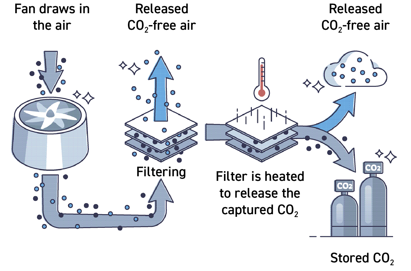
Carbon-negative infrastructure is required to solve the problem. The most efficient, effective, and scalable method to help lower CO2 emissions is the use of Direct Air Capture (DAC). Direct Air Capture is a technology that enables the separation of CO2 from air to create the products the economy needs such as agricultural products, building materials, fuels, plastics, and chemicals. DAC also enables sequestration, the ability to store CO2 for constructive purposes, turning it from a threat to an opportunity (Fig. 1).

At the heart of carbon capture are some relatively simple chemical reactions. Any carbon capture and reclamation system must operate at extreme efficiency to ensure it is not adding to the problem by consuming carbon-heavy fuels or emitting further carbon into the atmosphere– in other words, we must capture as much carbon as possible while using significantly less carbon than we are capturing to produce the reaction. Ideally, the goal is zero carbon input for unlimited carbon reclaimed as output.
The benefits of AM
Removing carbon from the atmosphere requires a system of filters, heat exchangers, condensers, gas separators, and compressors. Many of these complex parts require geometries that are well suited to Additive Manufacturing, which is more efficient and potentially more cost-effective than traditional fabrication methods, and delivers substantive performance and economic benefits in DAC equipment. These include:
Design optimisation for energy efficiency
When we direct the design optimisation capability of Additive Manufacturing toward these carbon capture and utilisation systems, we have the potential to dramatically boost performance and efficiency, approaching lossless energy.
Design freedom
Additive Manufacturing enables freedom of design to express the novel architecture required to efficiently capture and process carbon from the atmosphere and do something useful with it.

Performance
Capable of production with a range of alloys that are high temperature and corrosion-resistant while possessing high thermal conductivity.
Scalability
Rapidly available via scalable manufacturing to support the massive need in the field for equipment.
Streamlining of the supply chain
Part consolidation and monolithic design enable quality and streamlining of the supply chain. We cannot overlook the carbon footprint of using multiple suppliers across the country to produce a single assembly.
The application of AM in carbon capture solutions
Additive Manufacturing satisfies all of the requirements for the production of such reactors and can enable applications that address a variety of needs for carbon capture:
Mechanical filters
A critical component of carbon capture is ‘catching’ the carbon with a structured mechanical filter, typically coated with an amine that attracts carbon. Air is drawn into the system through the first (i.e., direct air contact) stage. Direct air contact filter efficiency can be optimised by filter structures that allow for maximum contact between incoming air and the filter surface. AM enables the function-first design of such filters which can induce high levels of turbulence and mixing as well as high surface area for maximum air contact.

Microturbine equipment
Microturbine equipment is an emerging technology in various industries, including power generation. They present an opportunity to provide high-pressure, high-efficiency gas and fluid conveyance, in a small form factor, with a minimal energy/carbon footprint. Efficiency in carbon capture is much like power generation in general: a function of yield over energy input.
Heat exchangers
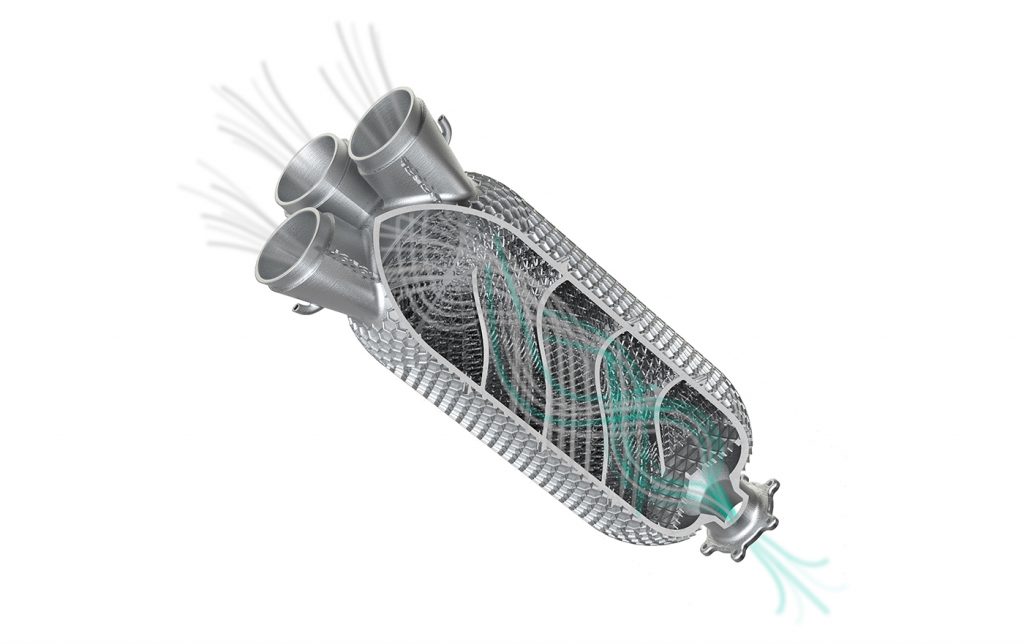
Heat waste is a common problem in carbon capture. Carbon captured in the direct air contact stage must be evacuated from mechanical filters into downstream refinement stages. In many embodiments of the technology, this is done via pressurised steam liberating the carbon from the filter. Heat exchangers can be applied to eliminate surplus heat from the steam generation process and – more commonly – downstream, reducing the temperature of the carbon-rich steam which exits the filter stage (Fig. 3).
Diffuser plates
These are commonly applied in chemical processing to take some volume of gas or fluid and collimate it. Fluid diffusion works similarly to the concept of light collimation which takes a light source and organises the energy so that light is emitted diffusely with parallel beam paths. Diffusor plates are very similar to a garden hose spray nozzle which takes a chaotic fluid flow and produces a structured and even flow. Liquid diffuser plates are important components of process stacks to ensure uniform flow and treatment of carbon-rich fluid as it moves through the process.

Manifolds (liquid, gas, and vapour)
Carbon capture is a chemical process which involves fluid and gas combined with chemistry, temperature, and pressure. Manifold applications in carbon capture are numerous ranging from chemistry conveyance into process chambers, to efficient distribution of coolant to active cooling components such as heat exchangers, as well as general gas distribution applications.
Chillers and distillers – the focus of this article
The carbon-rich product which exits the filter stage can be considered ‘dirty’ and in need of further refinement to be usable. This dirty carbon post-processing can be accomplished outside of a self-contained system, but it implies even more carbon will be produced in the logistics of collecting and transporting dirty carbon product to secondary post-processing facilities. The most valuable and promising carbon capture systems have some level of integrated dirty carbon product post-processing using chillers and distillers (Fig. 4) such that the output of a carbon capture system consists of clean usable carbon product, and safe water-based by-product.
Design of a high-performance refinement process column
Our goal is to create a process module that takes warm/hot steam full of carbon product as input, and produces refined, concentrated carbon product. To accomplish this, we want to be able to chill the gas to create a condensate and provide ample surface area for condensate to collect and create precipitate. Additionally, it’s desirable to have monolithic parts that require little to no assembly and a limited supply chain.
Conceptually, the designer can break this solution down into three components that can be considered independently and combined into a final concept:
- Process chamber design:
The process chamber provides an airtight structure to contain the components of a chemical process or reaction. There may be thermal, pressure, flow, and instrumentation requirements applied to it - Chiller design:
The chiller needs to provide temperature control to rapidly cool hot gas - Structured packing:
The structured packing should provide a high surface area that will thermally couple to the chilling mechanism as a super structured packing (SSP). SSP should provide surface area for condensate to form
Process chamber design
Process chambers – and process stacks in general – are implemented in many industries, from petroleum refineries to paint factories. A process chamber’s purpose is to create a controlled environment for a chemical reaction to occur where temperature and pressure must be maintained.
If you remember your high school chemistry, you will recall the concept of standard temperature and pressure or STP. STP is simply a set of constant values which can be used to calculate a chemical reaction product. For a DAC system, there is a different set of temperature and pressure constants (non-STP) that must be maintained in order to facilitate the desired chemical reaction. The process chamber ensures a steady state operating environment and contains the reactive components of the process. Imagine turning a benchtop chemistry set-up into a single monolithic process unit that accomplishes the same task, but is industrially deployable.
Shape, size, and aspect ratio
Process chambers are typically long pill-shaped cylinders, but not exclusively. The dimensions and aspect ratio of the process chamber are discoverable through numerical methods. For the purpose of this article, we cannot disclose the actual aspect ratios and details, but we can indicate that there is a relatively high diameter:height ratio in the process chamber.
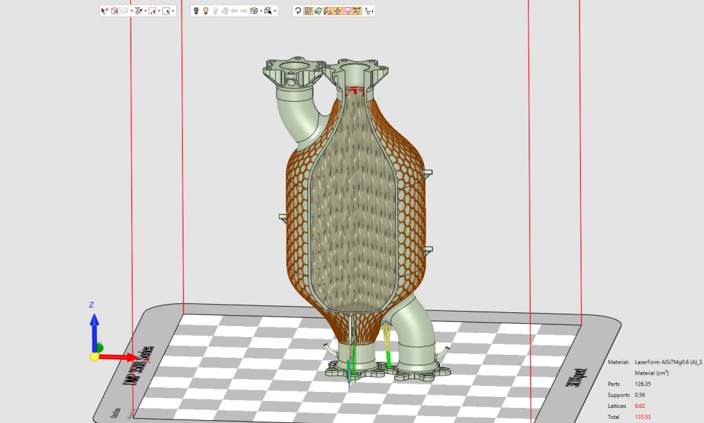
Due to the high aspect ratio for the specific efficiency targets, we designed the chiller modules to be additively manufactured at nearly the full height of our 3D Systems DMP Factory 350’s build chamber, approximately 400 mm, then combined in a stack. However, for smaller scale non-industrial, more commercial systems it is entirely possible to additively manufacture a complete process module in one piece, with one build.
For industrial, high-output stacks, using a modular approach affords you some advantages, allowing you to change the parameters of the module and have different packing and cooling densities per module (if required). Process modules are then joined with a simple spacer flange, which also allows for instrumentation and injection ports at various heights.
Material and wall thickness
316L stainless steel is one acceptable choice for process chamber material. Its thermal conductivity is in the acceptable range to be used in the chiller and condenser sections. Therefore, we chose this steel alloy for our Laser Beam Powder Bed Fusion (PBF-LB) process.
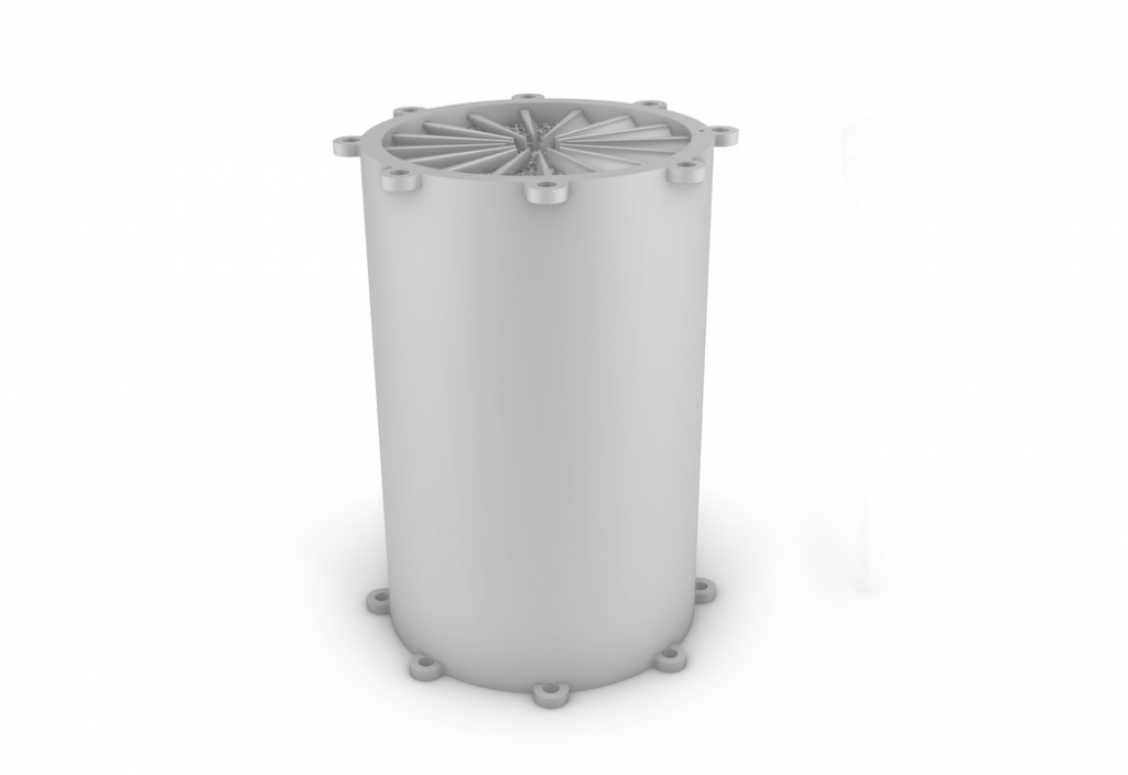
In the case of our refinement process column, which requires chilling (covered in the following section), we selected a dual-walled vacuum process chamber in order to provide a thermal barrier and insulation (Fig. 5). Additive Manufacturing allows for the creation of a vacuum insulation cavity. This space will need to be depowdered after manufacture, and possibly chemically cleaned, before vacuum pressure is drawn into the cavity and the cavity sealed to contain the vacuum.
Additionally, some process chambers require significant pressure (as high as 1450 psi) and temperature to sustain a chemical reaction. ASME B31.1 & ASME B31.3 standards indicate that for 316L stainless steel process chambers of approximately 100–125 mm in diameter, the wall thickness should be approximately 3 mm to contain 1160–1450 psi of pressure.
Chiller design
In designing a columnar chiller, there are many strategies one can use to cool the process components. In the case of the refinement chamber for DAC, one requirement is to have very even, controlled XY planar cooling – ideally progressively colder temperatures travelling from the bottom to the top of the chiller.
Considering this, an immediate comparison can be drawn with other well-known cooling applications which provide even planar cooling. An abstraction can be made from the design concepts employed in cold plates in general including semiconductor capital equipment wafer tables. In a previous Metal AM article (Vol. 7, No. 2, Summer 2021, p. 123), we detailed strategies for designing efficient cold plate designs which deliver extremely low cooling gradients across a planar surface. If one was to extrude a cold plate cooling strategy in the Z direction, theoretically one could provide an acceptable cooling gradient across any XY plane.
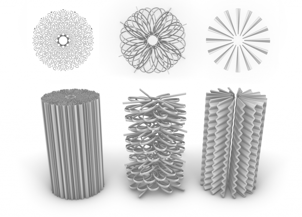
This would be a good starting assumption, but in implementation, it’s not so straightforward. A columnar cooler must provide a geometry which will encourage mixing/turbulence at the cooling surface; a lengthier and more complex path for coolant to ensure loitering of the coolant to resist gravitational forces; inlet and outlet strategies to counter the natural tendency for heat to rise and cold to sink; in the case of the chiller, the opposite needs to occur; and some space for additional functionality (i.e., condensation) beyond just chilling. Fig. 6 shows three possible strategies for the design of the chiller:
- Extruded 2D cooling:
While this possesses a significant cooling area, it is not enough space for any condensate formation; this design is intended for cooling only in planar space - Spiral cooling line:
This strategy has less cooling area and more condensate space. In general, this enables less efficient cooling because it has very high-temperature variation across the XY plane. Additionally, the longer cooling line paths become very difficult to effectively clean - Hollow periodic fin array:
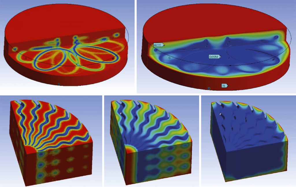
This enables highly efficient cooling due to its hollow fin geometry and offers plenty of room for structured packing for condensate. Fig. 7 shows transient analysis of the cooling performance of spiral line and hollow periodic fin radial arrays
Benefits of the hollow periodic fin radial array
As we have shown, the hollow periodic fin radial array satisfies the intended requirement of extremely low or no cooling gradient across the XY plane, as well as a significant magnitude of cooling, providing a chilling effect. There are several key aspects to the design of the periodic fin array:
Constant cooling volume
When taking any lateral cross-section up and down the Z axis, you should get nearly the same total cooling volume. This ensures that no matter what the cooling capacity of the structure is, it will be even planar cooling capacity.
Hollow core
This is less of an intentional design feature, but rather a manufacturability and functional compromise which provides acceptable behaviour. If all cooling fins converge in the centre, then you can imagine they become infinitely thin at the centre. Because of this, we need to cut back the fins so that the fin thickness along the axis is additively manufacturable. This compromise is acceptable because the radiative cooling effect of the axial faces of the fin directs cooling towards the centre and provides even and constant cooling in the axial core.
Period fins
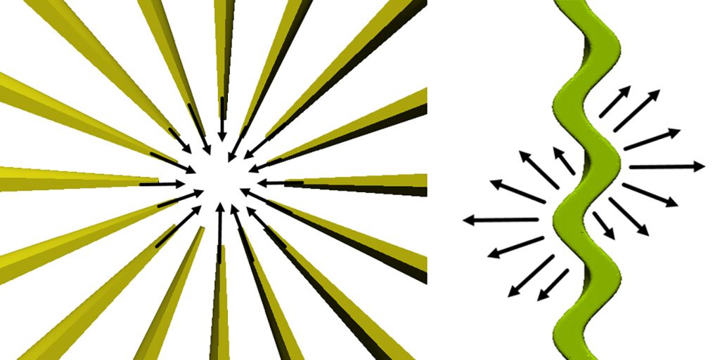
A non-periodic hollow fin would provide a very direct path to ground due to gravity. This could be acceptable but, in our case, we want the coolant to loiter and mix in the fins to provide significant cooling. A periodic fin also provides radiative cooling in many vectors, spreading the volumetric cooling potential for any cooling surface area unit over a greater space (Fig. 8). When combining many periodic fins in a radial array, the volumetric cooling potential zones are overlapping. Periodic fins also provide a more tortuous open area for condensing lattice. In this case, we want the gas passing through the inter fin lattice to loiter and mix in pockets to encourage condensate to form.
Structured packing
In CCAP, structured packing is a common concept and need. As previously stated, the function of direct air capture systems is to capture ambient air or flue gas and force it through a series of process chambers where a series of chemical reactions occur and concentrated carbon is a product. Through this process, input gas needs to come in contact with surfaces or other materials and gases for reactions to occur (hence the term ‘direct air contact’).
In the case of a refinement process module, there are several requirements some of which may be quite familiar to the reader, and very similar to AM active cooling applications. Cumulatively, these requirements are to ensure the lowest possible energy input, lowest possible carbon footprint, and highest possible carbon output, cumulatively contributing to a significantly net negative carbon reaction.
The requirements include a low-pressure drop across the volume (it’s ideal for the minimum amount of energy to be applied to force air into the process chamber; pressure drop increases back pressure, requiring even more input to force air into the system), high surface area (the gas needs to contact as much area of the chilled axis as possible) and control over packing density across the Z direction.
There are some traditionally manufactured options for structured packing including corrugated sheet metal, and advanced metal foams and these could be acceptable if the requirements for the surface area are quite low, and the required geometry is very prismatic and regular. Where traditionally structured packing falls short is in cases in which performance is critical, significant surface area is required, variable density is required, and conformal structured packing (i.e., super structured packing) is needed. It’s possible to purchase off-the-shelf structured packing in a range of packing densities, but the lead time on assembled packing and structural integrity become a risk.
Alternatively, it’s simple to additively manufacture structured packing in any density and even as a consolidated monolithic part combined with other functional elements. This can be referred to as super structured packing. Super structured packing comes with almost static cost, no matter how you change the structure or what space it fills. Corrugated sheet metal products have limitations in packing density and available surface area.
Traditionally manufactured metal foams come in various configurations of packing density and gradient density, and are machinable, but the extent of machinability is constrained by a cost function. The more complex the machining required the higher the cost of the end foam product.
If machining of the foam is an option, final integration into an assembly adds lead time and complexity, and makes the option not as attractive as additively manufactured structured packing which can be integrated into monolithic components. However, traditionally manufactured foam is a highly efficient structure with an attractive cost of goods.
3D Systems conducted significant studies on the comparability of additively manufactured packing with other methods, including the thermal conductivity and pressure drops associated with packaging. These efforts were done in conjunction with technology partner ERG Aerospace. Even though this is a study on an additively manufactured process chamber, we do have to concede that traditionally manufactured foam is a viable option for many cases of more discrete and prismatic use cases.
Packing geometry selection
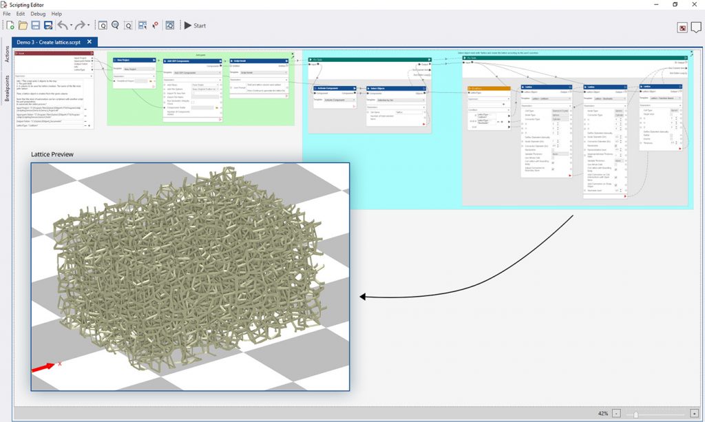
An extensive study was performed on a range of structures and densities to find an ideal balance of surface area and turbulence while keeping the density at a reasonable level to not induce back pressure. Oqton’s 3DXpert software was used to generate structural options. With 3DXpert’s latticing kernel and the newly available visual scripting tool, we were able to create a recyclable scripted routine that could sweep through lattice parameters and rapidly generate samples for us to additively manufacture (Fig. 9).
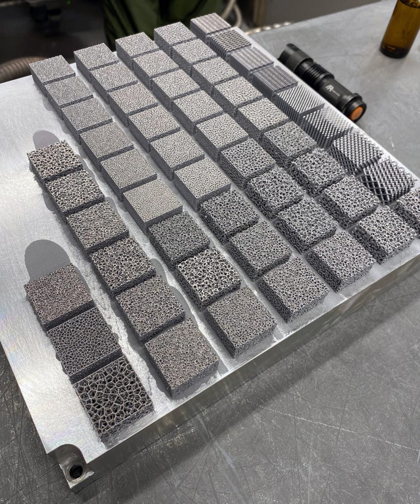
In previous exercises, weeks were invested across several software packages to generate lattice options. With visual scripting, we could generate dozens of additively manufacturable samples automatically within one hour. We could have taken this even further and automatically configured a build tray, simulated, and sliced to additively manufacture – all without the need for user intervention. The full suite of additively manufactured test cases for structured packing is shown in Figs. 10 and 11.
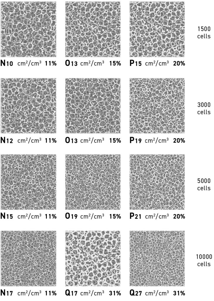
In this study, we found that the gyroid shape is often a popular instinctual choice for packing and cooling and lattice applications. The challenge is that gyroid does not provide optimal surface area for highly efficient absorption, and adsorption, to catalysis. It looks nice, but is not very functional for our purposes.
A standard beam and strut lattice arranged in XYZ directions, aka a simple rectilinear lattice, provides higher surface area and better flow-through pressure characteristics. However, at higher pressures and air speeds, laminar flow develops and mixing is minimal. This translates to increased efficiency in air contact, but the potential loss of contact as air can pass directly through the open areas without coming into contact with structured packing at all, or having limited contact which reduces the time for a reaction to occur.
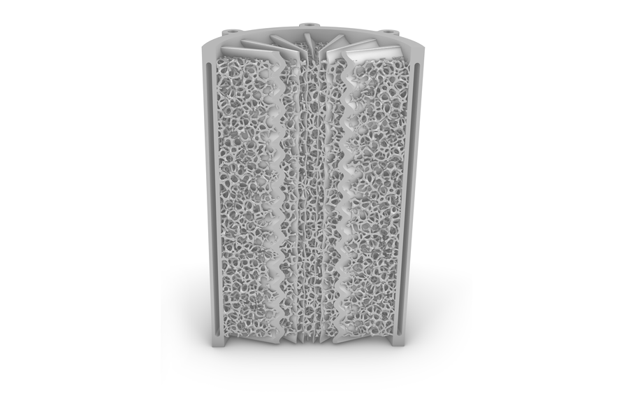
Using a randomised additively manufactured foam, such as a voronoi, or stochastic, foam tends to provide the most ideal results. It’s an ideal combination of high surface area, acceptable pressure drop, and randomised structures, which contribute to mixing and turbulence. We also further found that volume densities of structured packing above ~18% density started to negatively impact flow through, and increase back pressure
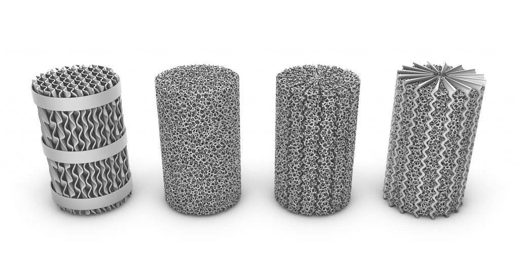
Net results
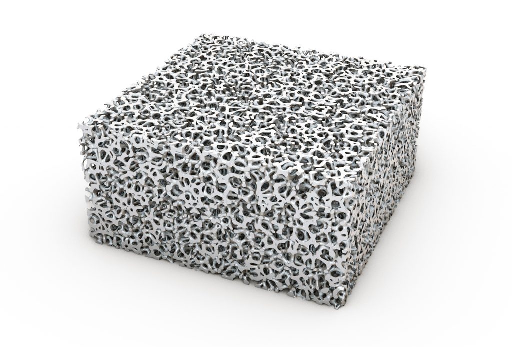
When comparing additively manufactured foam (Fig. 12) to the off-the-shelf options (Fig. 13) to there are some clear advantages and disadvantages:
Corrugated sheet metal
- Pro: Standardised stack shapes can be relatively cost effective
- Con: Limited surface area over other options, not shapeable or formable
Billet metal foam
- Pro: Low cost, good material selection, high-efficiency structure, machinable
- Con: Super structured packing or extensively conformal structures require assembly, including braze welding, increasing the overall cost
AM foam super structure
- Pro: Infinitely tuneable and shapeable to fill any space in a monolithic part assembly. The complexity comes at a static cost
- Con: With current PBF-LB machines, significant laser drawing time is required to produce the structure, and advanced cleaning techniques may be required
Bringing it all together
We have now independently conceptualised the three main components of this refinement process chamber. Next, they must be combined to complete the full solution by digital integration.
As previously indicated, we used Oqton’s 3DXpert software heavily in the design process. 3DXpert was a single solution for design, simulation, build preparation, and slicing. Major advantages of this approach in the design space are 3DXpert’s ability to use visual scripting combined with the lattice kernel to rapidly iterate through lattice structures and find a range of ideal cells and densities; implicitly model the periodic radial fins; and B-rep CAD model the prismatic features of the process chamber.
A hybrid modelling approach was critical to this effort: it allowed us to use only the necessary representation for each component of the solution and with maximum efficiency, all within the scope of Additive Manufacturing. 3DXpert also has the unique advantage of allowing Implicit, Lattice Rep, Mesh, and B-rep CAD to be all components of one part with no need for reduction in fidelity with the conversion down to common polygon mesh format.
Prior workflows involved three-to-five different softwares, each with their own advantages and geometry representations, and then a labour-intensive process of combining the disparate components into polygon mesh format with extremely heavy booleans and long calculation times, and major workflow blockers when having to regenerate any component of the process chamber, having to repeat the export, boolean and merge operations.
The only thing left to do at this point was to additively manufacture. For this, we used the DMP Factory 350 with 316L stainless steel alloy, depowder, wire EDM, and chemically clean the process chamber.
Future benefits
Direct air capture and refinement is a critical technology for correcting atmospheric carbon levels, and Additive Manufacturing is currently enabling significant efficiency advances in the technology. 3D Systems and its partners are making great strides in our collaboration – by utilising AM to quickly iterate and manufacture production-ready components, we’re able to apply never before used, high-efficiency geometry to process stacks and thermal exchange.
This newfound ability is increasing capture efficiency while reducing form factor and footprint, making the technology easy to install and ultimately to scale up. With further adoption of advanced manufacturing technologies and design tools, we believe we can rest a bit easier knowing that the climate may still be comfortable and liveable for future generations.
Authors
Scott Green
Principal Solutions Leader
3D Systems
Dakota Black
Industrial Designer
3D Systems
Matthew Atwood
Founder & CEO
AirCapture LLC
Christopher L Douglas
Professor of Mathematics, Mathematical Institute
University of Oxford
LAST MONTH’S MOST-READ ARTICLES


