


AMPM2016: Developments in binder jetting technology highlighted at Boston conference
For the third consecutive year, the Metal Powder Industries Federation’s Additive Manufacturing with Powder Metallurgy (AMPM) conference was held in parallel with its long-established POWDERMET conference. This year’s event took place in Boston, Massachusetts, USA, from June 5–8, 2016. In the first of our reports, Dr David Whittaker reviews three presentations that focused on the binder jetting process. [First published in Metal AM Vol. 2 No. 3, Autumn 2016 | 15 minute read | View on Issuu | Download PDF]
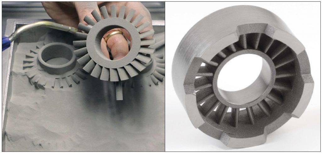
The binder jetting process uses a glue-like binder selectively deposited from a print-head to form 3D shapes, layer by layer, with debinding and sintering of the built component being included in the post-build operations. The build process itself is a low energy and low thermal input process that has the capability to work with any material that can be processed into powder and bonded together. One of the major questions with binder jetting is what process parameters, for both the materials and machine, are optimum for printing parts.
Binder jetting of metals and ceramics
A presentation made by Dongguo Lin (Pohang University of Science and Technology, South Korea) and co-authored by Sundar Atre, Jason Porter, Tim Batchelor and Kunal Kate (University of Louisville, USA), Seong Jin Park (also Pohang University of Science and Technology) and Matthew Bulger and Paul Gangopadhya (Netshape Technologies, USA), described a process optimisation study for the binder jet building of a Type 420 stainless steel and introduced a numerical model for thermal debinding accompanying its application to binder jetting.

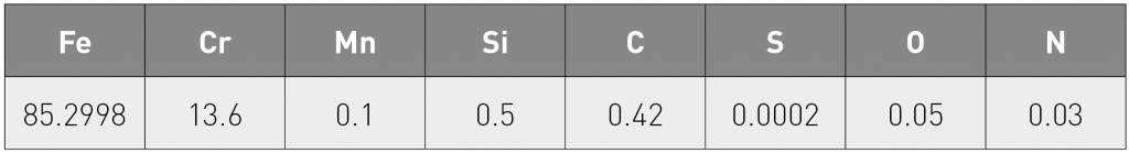
The 420 stainless steel powder used had a median particle size of 12 µm and the chemical composition is shown in Table 1. The binder used for the process was Lab Binder 04, a solvent based binder supplied by ExOne. This binder uses polyvinylpyrrolidine (PVP), a water soluble polymer, as its main bonding agent. The parts built in these trials were 7.5 mm cubes. An ExOne M-Lab machine was used to create parts. This binder-jetting machine features a 50 x 70 x 34.5 mm build bed.
For the reported experiments, heater power, heater time and print speed were all kept constant. The layer thickness, spread speed and binder saturation were varied to determine their impact on part quality. Saturation is a computed value within the ExOne program defining how much binder is applied to a given area. This is represented by
- Saturation Level = Vbinder/Vair
- where Vbinder is the volume of the binder droplets and
- Vair = 1-(PR/100)* Xspacing *Yspacing *Layer thickness
where PR is the packing rate of the powder, a ratio of the tap density and nominal density. The layer thickness controls how much the Z axis of the part changes per layer. The spread speed indicates how fast the roller traverses when spreading the powder over the build chamber.
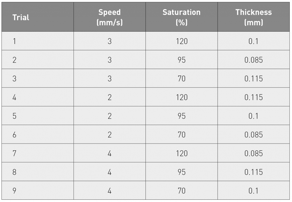
To determine the influences of these variables, a 3 x 3 Taguchi matrix was created (Table 2). Using the Taguchi method, nine different processing combinations were applied. For each combination, four parts were built and tested, i.e. a total of 36 parts to give an average value and standard deviation for each particular combination. After the parts were built, they were cured in an oven at 200°C for two hours to activate the binder and densify the part. All parts were then evaluated in the green state, before debinding and sintering. Each of the green parts from the trials is pictured in Fig. 2 and is labelled with the particular trial number.
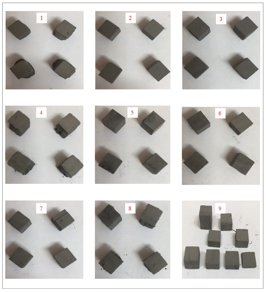
Trial 1 showed large errors in the X and Y directions due to the high saturation value of 120. The binder pooled on the build plate causing extra powder to be bonded to the lower layers of the part. Trial 1 had the highest overall dimensional and weight error.
Trial 2 parts were the second best in terms of dimensional error. The parts showed very good edge definition, although surface pores and deformation could be seen along some of the part sides.
Trial 3 parts showed very good edge definition as in Trial 2, but featured more pores and deformation on the sides of the parts.
Trial 4 parts experienced the second largest error in the X and Y directions because of the high saturation value. The large amount of binder once again caused excess powder to be bonded to the parts, specifically near the bottom of the parts. Edge definition was poor and many cracks and obvious locations where sections had broken off were observed.

Trial 5 parts showed pores and surface roughness along the sides of parts starting from the bottom of the part. The first layers of the part featured both pores and excess powder, creating a very rough surface.
Trial 6 parts featured very good edge definition and low dimensional accuracy error. The surface finish of the parts was smooth with no obvious pores or defects visible.
Trial 7 parts showed very good edge definition, similar to the parts in Trial 6. One Trial 7 part did show part separation along a crack.
Trial 8 parts showed poor edge definition as excess powder was bonded to the faces of the cubes. The parts featured good edge definition, but the excess powder led to a high dimensional accuracy error.
Trial 9 parts showed very good surface finish and edge definition, but broke into sections. Only one of the four cubes remained intact, with the other three breaking into a total of seven parts.
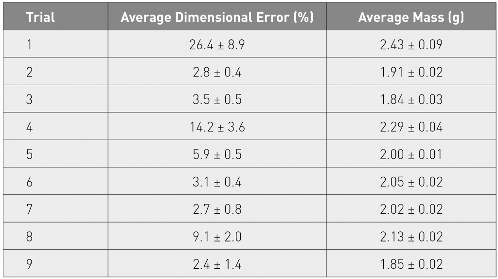
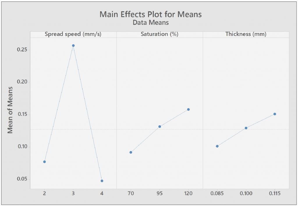
The average dimensional error and average mass values were calculated for each trial (Table 3). Trials 1 and 4 had the highest mass values because they both used a saturation value of 120. Trial 7 also had a saturation of 120, but had a lower mass because of the smallest layer thickness of 0.085 mm. Using ANOVA and the L9 Taguchi results, the parameters that caused the least dimensional error were determined. This is illustrated by a mean of means graph for each parameter, Fig. 3, which shows that a spread speed of 4 mm/s, a saturation percentage of 70 and a layer thickness of 0.085 mm will create the best parts dimensionally, with sharp corners, a smooth surface finish and few if any surface defects.
The second part of the reported work involved the development of a numerical model for thermal debinding and its application to binder jetting. Thermal debinding is an important methodology for removing the binders in powder-binder mixtures and is widely used in the post-processing of binder jetted parts. Failure in this process can cause defects, including residual binder, cracks and contamination, in the final sintered parts.

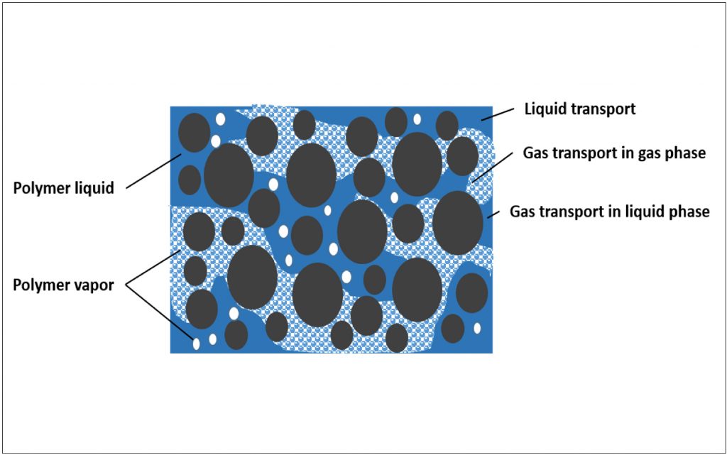
Thermal debinding is a complicated process combining binder evaporation, liquid transport, gas transport, pyrolysis of the binder and heat transfer in a porous structure. Fig. 4 shows the status of the thermal debinding process in terms of the complicated phases and phenomena that exist in the intermediate state. A numerical model for the thermal debinding process has been proposed to predict and optimise the binder removal process without trial-and-errors. The parameters affecting the debinding process were determined and systemically studied by a series of experiments. The main constitutive equations used for describing the thermal debinding process include mass conservation, mass concentration and energy conservation equations.
During binder removal by thermal debinding, the mass conservation equations for three different states (i.e. polymer liquid, polymer vapour and atmospheric air) were employed, as shown in following equations:
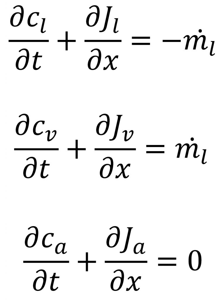
where ![]() is the rate of mass transformation of polymer liquid to polymer vapour, c is the mass concentration and J is flux.
is the rate of mass transformation of polymer liquid to polymer vapour, c is the mass concentration and J is flux.
The mass concentration can be also represented using the equations:
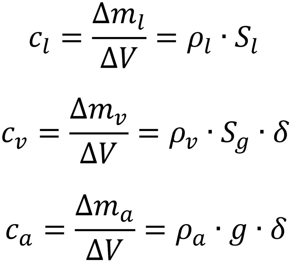
where S is the saturation of liquid or gas and δ is the porosity of porous media.
The energy conservation equation used in this work was:

where, is the effective thermal conductivity, C is specific heat capacity, Q is the rate of heat generated by binder phase transition and ∆Hvap is the enthalpy of binder vapourisation.
Using mathematical methods, the constitutive equations can be combined and the final form of the model can be expressed as:
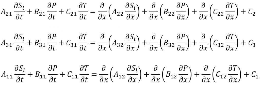
The coefficients in the final form are the functions of several material properties, including polymer liquid viscosity, permeability of porous media, polymer pyrolysis, polymer mobility, polymer diffusivity, capillary pressure, polymer vapour pressure, etc. These parameters should be determined by specific experimental routes or empirical models.
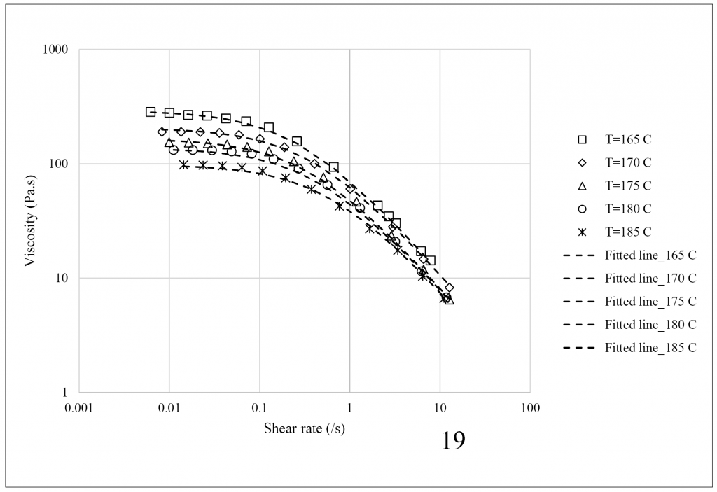
The polymer liquid viscosity at different temperatures was measured using a plate-plate type rheometer and the results were expressed using the Cross model. Fig. 5 shows the relationship between the shear rate and viscosity of polyethylene (the selected polymeric binder). The viscosity decreased with increasing temperature and shear rate.
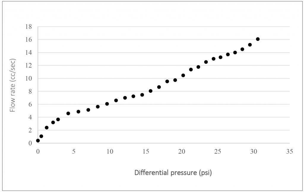
The permeability of porous powder media was measured using a capillary flow porometer. The sample was prepared by mixing 316L stainless steel powder with a polyethylene binder using a twin-screw extruder and was moulded and debound before measuring its permeability. Fig. 6 shows the permeability testing results.
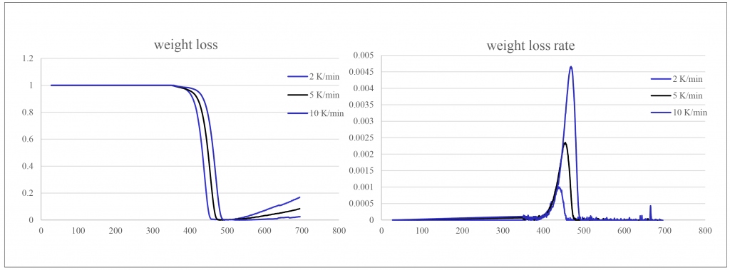
The polymer pyrolysis behaviour was studied using thermal gravimetric analysis (TGA) experiments. Fig. 7 shows the polymer pyrolysis behaviour of polyethylene, which was expressed using the polymer decomposition equation.
The experimentally derived material coefficients can be introduced into the proposed numerical model for the analysis of the thermal debinding process in binder jetting.
A clear path to large AM parts
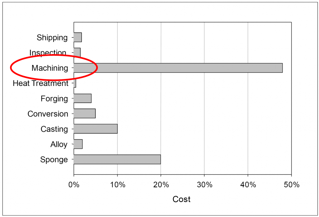
A presentation from Eric Bono and Fred Yolton (Puris LLC, USA) discussed their company’s focus on the 3D printing of large parts and the reasons why binder jetting AM technology has been adopted as an enabler for this objective. The presentation began with the outlining of the driving forces for the adoption of near net shape forming in general and of powder-based forming technology in particular, with particular reference to large aerospace components. Near net shaping is driven by the desire to eliminate machining operations as a recognised major contributor to total component costs (see Fig. 8). In addition, powder-based routes offer superior control over fine microstructures, isotropic properties and reduced scatter in achievable properties.
The challenges in Additive Manufacturing of large parts were defined as:
- Residual stress control
- Avoidance of microstructural degradation
- The impact of powder costs
- Processing speed (or lack of it)
- Scalability of equipment
The benefits of binder jetting over AM technologies involving powder melting in addressing these challenges were discussed. It was stated that uneven heating during build up with powder melting makes residual stress control in large parts and at corners challenging. The expedient of removing a part-built component from the system and stress relieving before continuing with printing is often employed. On the other hand, as binder jetting is carried at near-ambient temperatures, residual stress generation is not an issue. Whereas any powder melting technology alters the powder microstructure significantly, binder jetting retains the starting powder microstructure and results in a microstructure akin to direct HIPping.

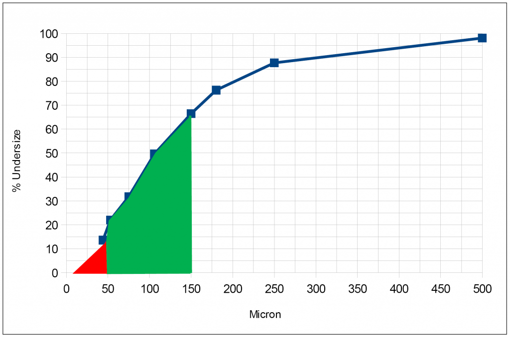
Powder costs, of great significance in large part AM, can be controlled in binder jetting through the ability to use a somewhat wider and coarser particle size distribution (Fig. 9). The limitations in the capability for multiple re-use of powder in Electron Beam Melting, without detriment to resultant component properties, were also highlighted in this context.
Although Puris is not an equipment manufacturer, its view is that it would seem easier to scale-up binder jetting in comparison to air-tight systems. Puris’ near net shaping approach was described as a holistic one, which was dependent on part shape, size and production quantities. Their ‘tool box’ was defined as including the largest 3D ExOne printers in the world and patent-pending powder densification technologies. In all cases, the processing technologies start from powder feedstock.
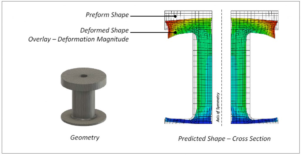
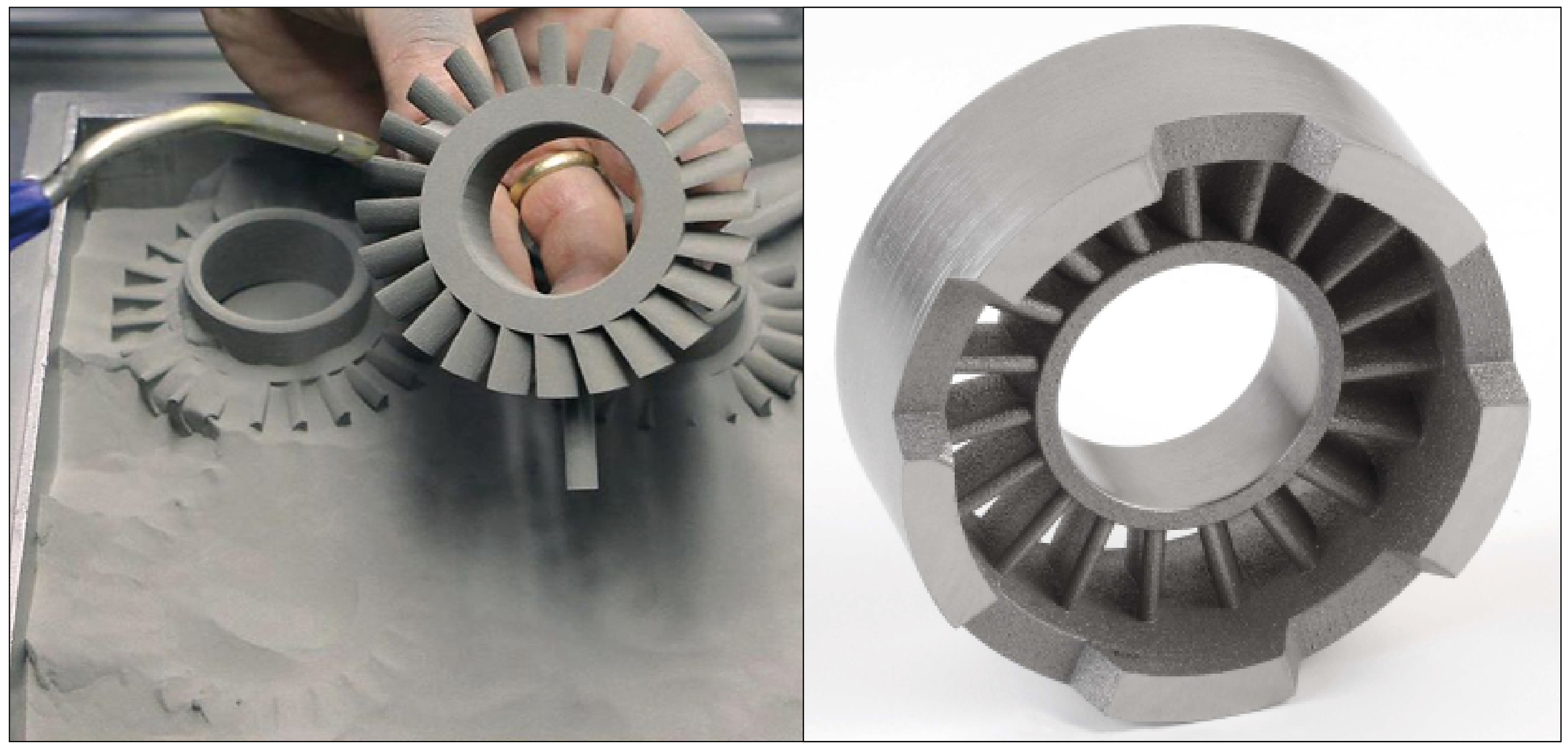
The AM printing approach involves printing of the component, followed by debinding, pre-sintering, canning and HIPping. Use is made of numerical modelling to quantify deformation during the HIP process (Fig. 10). Examples of current near net shape and complex shape applications are shown in Figs. 11 and 12.
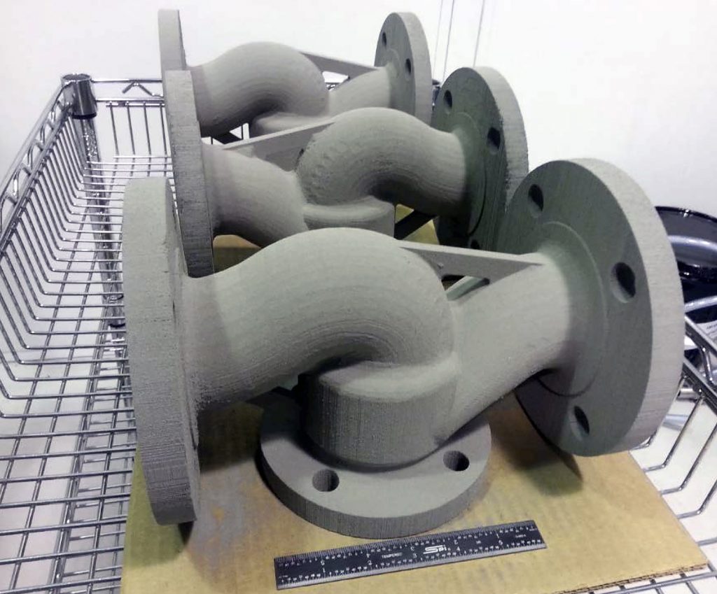

In summarising the current capabilities and limitations it was stated that there is a near limitless choice of materials available. The focus is on large components in the 5 -5,000 lb range and, in terms of the level of detail, the current minimum section thickness is 0.1 inch. Ultimately, investment cast tolerances will be targeted.
Inkjet printing without nozzles
A presentation from Chris Hole (The Technology Partnership, UK) was not directly concerned with binder jetting, but rather discussed a novel 3D inkjet printing technology. In its technology portfolio, The Technology Partnership (TTP) has been a major 2D printing technology supplier for more than 25 years. The presentation first highlighted the potential advantages of using electrostatic inkjet printing (as opposed to conventional mechanical ejection inkjet printing) in a 3D scenario for Additive Manufacturing. Principal among these advantages was the potential for very high build rates, as the use of highly parallel nozzle arrays is routine and the technology avoids the use of powder beds as the powder is carried within the ink.
Mechanical ejection inkjet printing does have some limitations (for example in the required use of low viscosity carrier fluids and in the occurrence of particle sedimentation). TTP has nozzle based (i.e. mechanical ejection) printing technology, which extends the viscosity and sedimentation envelopes significantly and is also capable of handling non-conducting materials (e.g. polymers). However, the key to enabling a step change in build rate was identified as the need to avoid the use of nozzles entirely and the main message of the presentation was therefore ‘inkjet printing without nozzles’.
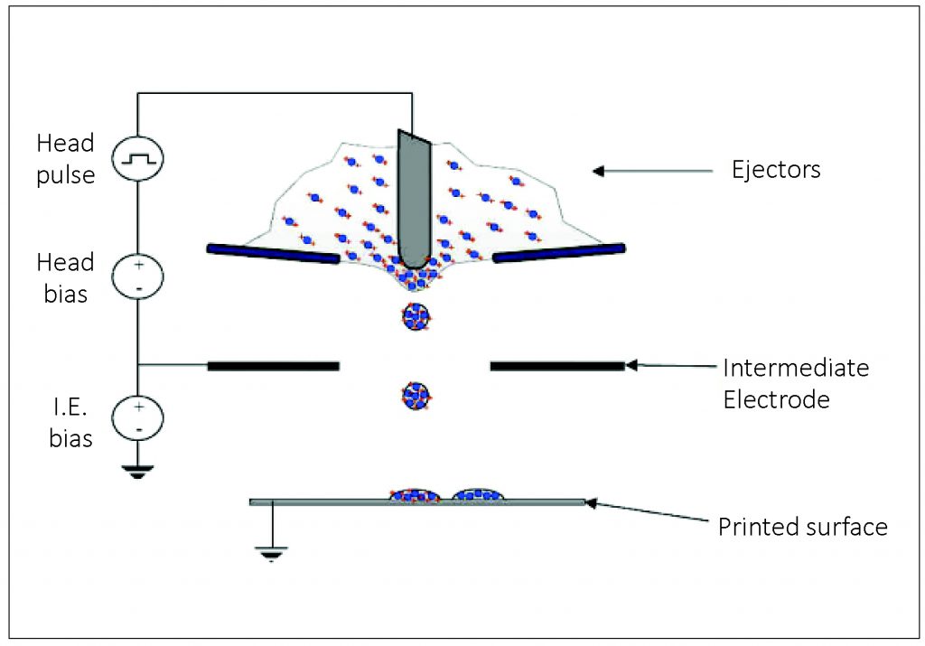
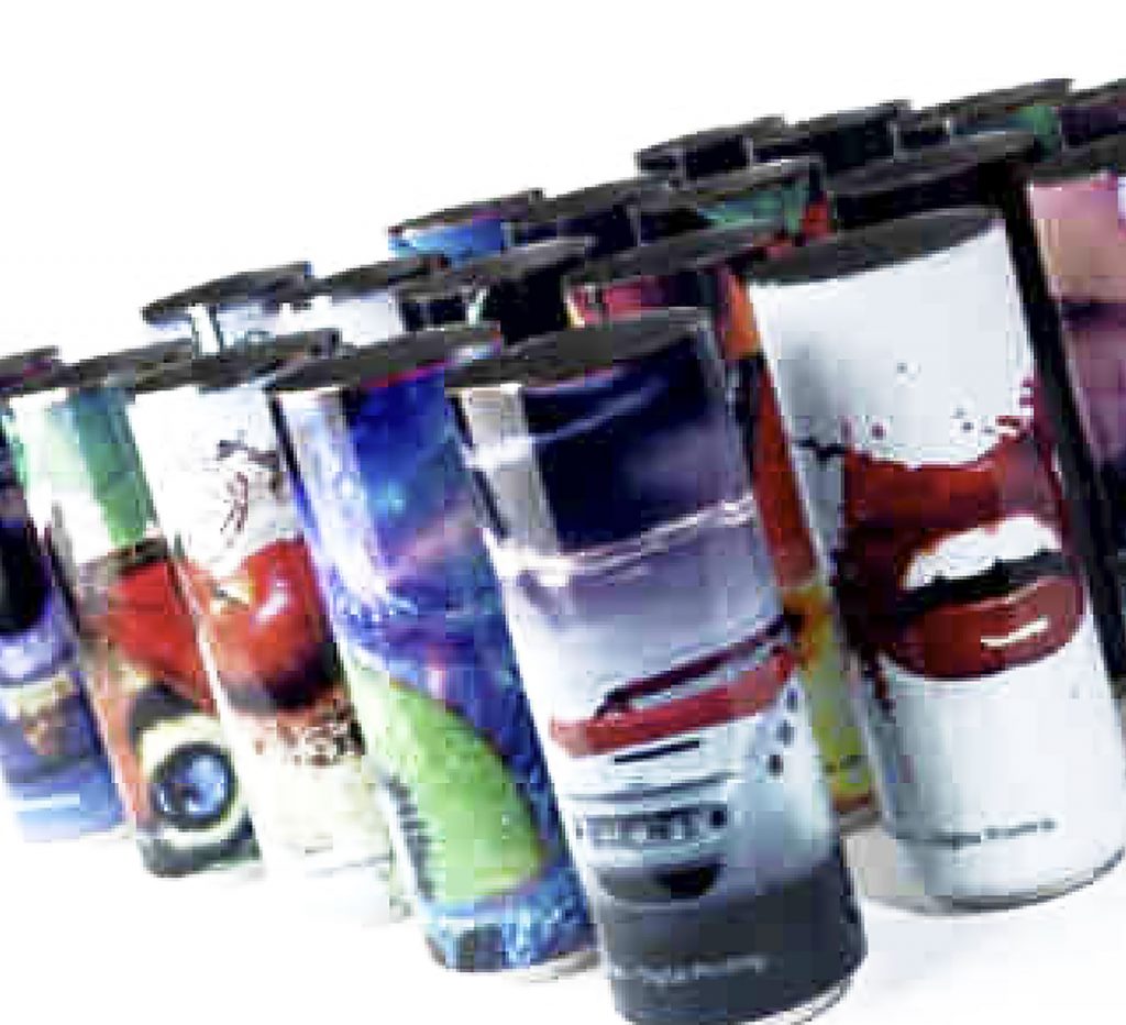
TTP’s development of electrostatic ejection as a means of avoiding the use of nozzles was then highlighted. The principles of this technology are shown schematically in Fig. 13. 3D printing with this technology was demonstrated around 15 years ago. However, at that time, the AM market was still small and, therefore, the company chose to exploit the technology in the 2D application area of direct to package printing (Fig. 14). With the surge in interest, the company has recently re-visited the AM market.
Existing solids deposition rate in package printing is 120cm3/hour (i.e. ten times faster than powder bed SLM) and higher build rates still are expected with the larger particles used in AM. The technology operates with four standard heads and with 5 µm layers, five times thinner than SLM. There is full multi-material capability and the technology could even work with SLM for multi-material powder beds (working as a digitally addressable re-coater bar). Drop size variation is also possible. Systems can be integrated with conventional inkjet heads.
TTP stated that it is now seeking to partner with an established AM equipment supplier in taking this technology forward and also to interact with leading users to develop specifications.
Author
Dr David Whittaker is a consultant to the Powder Metallurgy industry.
Tel: +44 (0)1902 338498
Email: [email protected]
References
[1] Binder Jetting of Metals and Ceramics, D Lin, J Porter, T Batchelor, K Kate, S Atre, M Bulger, P Gangopadhya, as presented at AMPM2016, MPIF, USA
[2] A Clear Path to Large AM Parts, E Bono, F Yolton, as presented at AMPM2016, MPIF, USA
[3] Inkjet Printing Without Nozzles, C Hole, as presented at AMPM2016, MPIF, USA
LAST MONTH’S MOST-READ ARTICLES


