


Cost and practicality of in-process monitoring for metal Additive Manufacturing
Additive Manufacturing gives industrial designers the freedom to create ever more complex and customised products. However, with the increasing adoption of the technology by sectors such as aerospace, where product failure can have catastrophic consequences, component verification is becoming a critical issue. In the following article Dr Chris Hole, from the UK’s TTP Group plc, reviews the challenges of verification in an industry that is associated with low volume runs of complex, often highly customised components with sophisticated hidden internal structures. [First published in Metal AM Vol. 2 No. 4, Winter 2016 | 20 minute read | View on Issuu | Download PDF]
Much has been said about the new capabilities and scope for customisation that powder based Additive Manufacturing offers, but in many cases true customisation is less important than the ‘complexity for free’ factor – production runs that are short and where parts are complex but generally not unique. In aerospace, complex shapes often come from the need to remove weight. In medical prosthetics a complex surface enables biological cells to infiltrate the structure and form a strong bond with the host bone or organ. Similar situations exist in other industries including automotive, motorsport, energy and antenna design.
Complex components create a problem however: verification. In many applications targeted by AM, component failure is serious and parts cannot be used unless reliable and trusted non-destructive testing (NDT) techniques exist, or the production process is so well controlled that companies and certification authorities accept a given set of manufacturing parameters leads unequivocally to a given set of performance characteristics. AM currently struggles with both these routes to verification. For example, the geometrical complexity of parts makes the interpretation of ultrasound returns from parts difficult [1] and eddy current probes often cannot access every part of the component’s surface. The alternative approach of strict process control faces the problem of the sheer number of process variables; Spears & Gold [2] list fifty important process parameters in metal AM and only twelve are typically under the control of the user. Roughly fourteen are largely controlled by the machine manufacturer, another fourteen by the powder supplier and the balance are not reliably under the control of any single party in the supply chain.

Given the above it seems unlikely that either post-production NDT or open loop quality control will provide adequate component verification for AM parts in many key markets for the foreseeable future; consequently the attention of both industry and academia has turned to in-process monitoring both for NDT and process parameter control [3]. There is a growing body of literature on ideas for in-process monitoring and their technical effectiveness, but so far less has been said about likely cost and practicality in an industrial environment. This article seeks to look at several of the leading in-process monitoring techniques and discuss factors such as cost, effect on build times, and compatibility with existing AM machines and work flows. It also looks briefly at how another industry has solved similar problems in the past.
Cameras and image processing
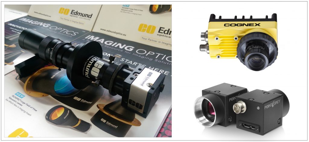
This is the most mature process and already offered by both machine manufacturers, for example EOSTATE from EOS and 3rd party vendors such as Sigma Labs. High resolution digital cameras are now cheap, but the lenses required to image the small melt pool, the conditions in the build volume and the requirement for high dynamic range push costs up to the $1000-$3000 range. If cameras are bought as part of a package along with image processing and product support, prices rise to the $7000-$12,000 region at the time of writing (Fig. 2).
With regard to machine vision and digital processing technology, huge investments are being made by other industries which will benefit in-process monitoring for AM at almost no cost to the AM community. The bigger problem for vision systems is to know which visual cues, once identified, are important. Solving this problem will require a lot of research funding and time but will probably not add much to the cost of manufacturing AM equipment. The sheer complexity may however enable those who develop good data to charge heavily for the knowledge if it can be embedded in AM design software.

Thermal imaging
One area where imaging costs have historically been high is thermal imaging at longer wavelengths (lower temperatures). Existing low cost CCD cameras have intrinsic sensitivity at wavelengths up to about 1.2 µm (if the IR filter is removed), which is enough for visible light spectroscopy [4] and for basic temperature estimation above about 400°C. Temperatures away from the centre of the weld pool however are too cold to be measured directly with a low cost camera, as are temperatures in polymer melt pools. True thermal imaging cameras have traditionally cost $10,000+ due to the high price of germanium lenses and sensor cooling, but new lens materials such as Cleartran (ZnS) can be bought for less than $200 even in one-off quantities. Improvements to sensors have also removed the need for cooling in all but the most demanding applications. As a measure of this cost reduction, companies such as FLIR and SEEK now produce room temperature thermal camera add-ons for smart phones for less than $200. Wavelength sensitivity of these systems goes out as far as 16 µm.
Melt pool spectroscopy
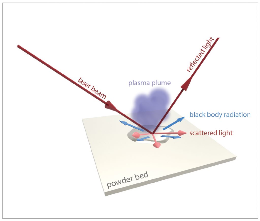
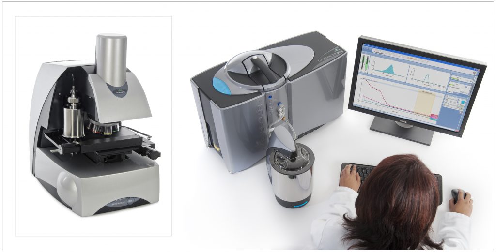
Spectroscopy techniques are well established in other industries and use signals from across the electromagnetic spectrum and also sound. Spectroscopic techniques are starting to be explored as a method for melt pool condition monitoring as well as material loss analysis of the plume above (Fig. 3). The cost of off-the-shelf industrial spectroscopy systems remains fairly high and the market for AM in-process monitoring is unlikely to be large enough to change this. However, the cost of the constituent parts has fallen substantially in recent years. Fingernail size spectrometers cost a few hundred dollars [5] and provide sufficient resolution for basic in-process melt pool monitoring in the visible light spectrum [4]. Today’s low cost detectors and microprocessors are enabling very low cost spectrometers to be built by the open source community for under $100 [6] which could enable spectroscopy across a wide range of AM systems.
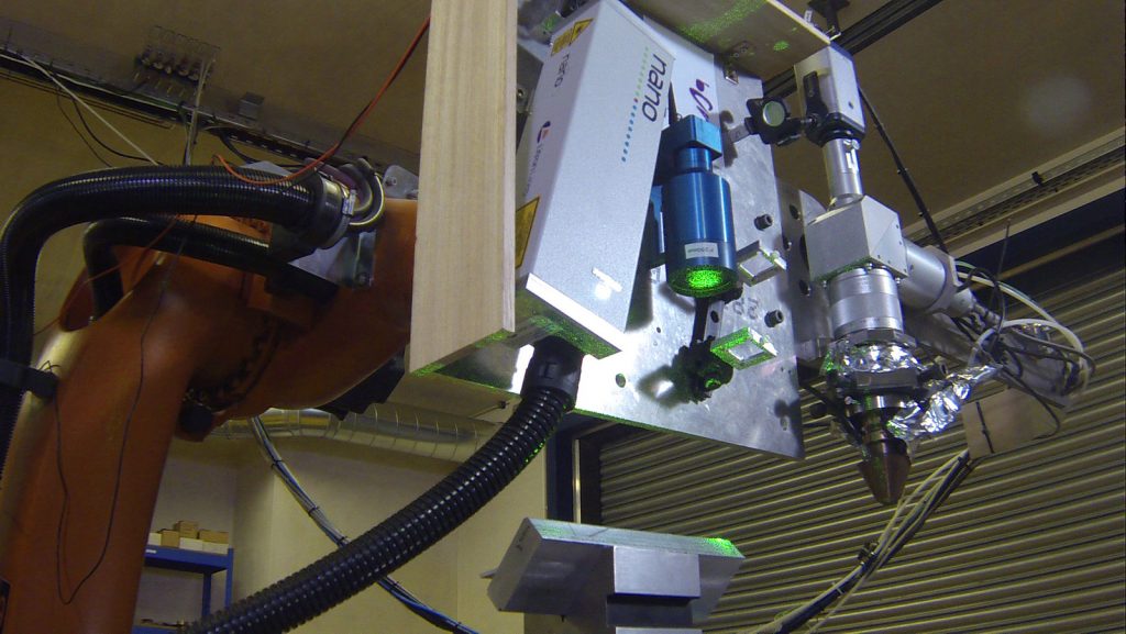
Laser Induced Breakdown Spectroscopy (LIBS) is a closely related technique to melt plume monitoring that has been developed by other industries, most notably the nuclear industry [7]. In LIBS a laser is fired at a surface which vaporises a tiny quantity of the surface material into plasma. The plasma is then analysed for its spectral content (Fig. 4). Researchers in metal AM are exploiting a similar process in the plume [2] and assuming useful information can be extracted the cost of existing LIBS systems gives a guide to likely cost in an AM context. A key factor here is that the main cost of LIBS systems is the cost and safety issues associated with the high power laser needed to ablate the material from the surface. In AM these problems have already been paid for in the form of the laser which is at the core of most powder bed fusion systems. The only additional cost is the receiver spectroscopy system which can be, as noted above, 100s, not 1000s of dollars. LIBS can operate over a considerable distance (even 10s of metres) from the surface being analysed, so a plume monitoring system is unlikely to interfere with the build process in AM.
Ultrasound and eddy current NDT
Cameras and spectrometers are fundamentally surface observation instruments, but many of the important defects such as voids and delaminations do not exist until further layers are deposited on top and their initiators are difficult to detect with a camera [8]. For applications that are not safety critical the assumption that a visually correct weld pool surface will correspond to the desired bulk properties is likely to be a cost effective solution but customers seeking to manufacture safety critical parts are likely to want a more direct measure. As a result this author suggests that subsurface techniques must eventually be developed for AM if it is to be used in these high value applications. Both ultrasonic and eddy current testing are widely deployed, and trusted, in the NDT of conventionally manufactured parts but are hampered by problems in AM.
- Geometric complexity of parts makes ultrasound reflections difficult to interpret.
- Coupling sound across the rough surface of AM components is difficult to do mechanically without liquid couplant
- Eddy current probes do not require physical contact but must be placed close to every surface of the complex AM part, many of which may not be easily accessible post build.
Surface access and ultrasound reflection complexity are naturally solved by in-process monitoring and the cost of existing NDT systems can be used to estimate what they might cost when integrated into an AM machine. An in-process eddy current system can be similar to a conventional one [9] and should have a bill of materials (BoM) less than $200 – although coil winding, signal processing and mechanical integration into the AM machine will probably drive total costs over $2000 given the small production volumes. Extensive use of bought-out subsystems could add another $2000-$3000. The bigger problem however is likely to be the need for the coils to be physically close to the fused parts of the powder bed and this could slow build times by constraining the optimal laser path. Time represents a major cost when the interest payments alone on a $400,000 AM machine are about $5/ hr.
Estimating the cost of ultrasonic NDT is more complex since true non-contact systems are not generally used in NDT today but would be required for practical in-process monitoring. Taking the system proposed by Liaptsis & Rudlin as an example [10], the cost is dominated by the interferometer and ultrasound generation laser.

Many different types of laser have been used to generate ultrasound but taking 8 ns pulsed as an example [10] high repetition rate lasers of this type are still tens of thousands of dollars but lower rep rate lasers used for tattoo removal are only a few thousand dollars and have adequate power. The price of this major cost reduction will be slower inspection rates which will impact build times significantly unless potential detector mitigation strategies are employed. The potential also exists to re-use the core AM laser to inspect each layer immediately after it is built. Again, this allows a major cost saving at the expense of longer build times.
Ultrasound waves are detected using a laser interferometer (Fig. 5). These can be fibre coupled; meaning most of the components could be installed away from high temperature parts of the AM machine but are very expensive if bought as scientific instruments. The system used by Rudlin and Liaptsis cost of the order of $100,000 but lower specification devices can be made for around $10,000 depending on the required sensitivity. The signal processing, data processing and other components should be less than $300 if there is no requirement to store raw data long term. Integration into a reliable industrial system which yields clear and useful data will be a challenge, but on the positive side there is a huge body of knowledge on the ultrasound signatures of defects in metals, polymers and composites that can be applied to many, though not all, of the defects seen in AM.
X-rays and X-ray tomography
To the knowledge of the author no industry has ever adopted X-rays with enthusiasm. Health and safety issues, both real and imagined, have always discouraged adoption unless no practical alternative exists. Perhaps the most recent example has been the security scanning of airline passengers. The United States TSA set the maximum radiation dose for backscatter X-rays scanners at <0.1 µSv per scan – or the equivalent dose of about 2 minutes of flying time at normal cruising altitude [11] – but their use still remains controversial [12]. Dentists routinely leave the room when administrating a dental X-ray and this behaviour would be difficult to replicate for an operator of AM machines in a production environment.
Despite the above, electronic and mechanical component inspection is carried out using X-rays (e.g. GE’s Phoenix range) but its use in NDT is declining relative to ultrasonics and eddy current systems. We suspect the industry would have to accept that no practical alternative exists before embracing the technique despite the high quality results from tomography in post-process inspection [13] and in porosity detection.

Powder characterisation
Particle size distribution is known to be a key parameter [2] strongly influencing the recoater process (forming each new layer) and minimum feature size of an AM process. Powder characterisation techniques are already well established from the Powder Metallurgy industry (Fig. 6) but many (e.g. avalanche angle and successive sieving) are slow and not suitable for in-process monitoring. Particle Size Distribution (PSD) measurement using laser light has been investigated by several researchers and can be implemented as a ring of low cost diode lasers and photodiodes around free falling powder for a few hundred dollars. In parallel a camera or shadow projection system could be used to estimate particle morphology one particle at a time, probably for a similar cost, but will only ever inspect a tiny fraction of powder grains. As a result this method is unsuitable for preventing point defects due to exceptional particles not caught by screening trays and neither method will detect changes in the flow of powder due to non-powder parameters such as humidity.
Given the above, direct machine vision monitoring of the powder flow during new layer deposition may be the only stand-off process capable of in-process monitoring of powder characteristics. If machine vision based melt pool monitoring is already implemented in a system then the additional manufacturing cost due to powder flow monitoring could be near zero since the melt and recoat processes do not occur at the same time.
Validated blocks of laser movement – an alternative to in-process monitoring
Given the large number of process variables discussed in [2], and their fragmented nature, it may prove impractical to adequately control them all, even in the long term. A similar situation exists in the semiconductor industry where a large number of manufacturing parameters affect the performance of a transistor and further parameters affect the way each transistor works in a given integrated circuit. While process control and transistor behavioural models have improved greatly over the last twenty years the problem of accurate process control has been solved in part by companies such as ARM [14] developing huge blocks of transistors and associated components which carry out high level functions. What ARM sells is essentially a complex electronic circuit schematic that other companies can drop into their overall chip design rather than repeating ARM’s design and testing work. Clearly the most obvious value to a customer is the avoidance of having to design something as complex as a microprocessor themselves, but the testing and validation ARM has done with each of the manufacturing processes it supports is crucial to ensuring the design works reliably and enables customers to slot together high level functional blocks like Lego to create a more complex product of their own that also performs predictably and reliably.
Another case of this is starting to occur in the area of molecular diagnostics, or ‘desktop biology’; research has always suffered from an inability to reproduce published results from one lab in others due to a combination of high sensitivity to experimental conditions and the large number of experimental parameters. The move to highly automated biological research equipment, driven by TTP and others, has enabled complete experimental parameters to be built up from software style subroutines of procedures and published via weblinks in academic journals allowing precise replication in other labs. This helps the research community but is also benefiting the equipment vendors because equipment now needs regular calibration and it enables market leaders to cement their position using de facto instruction standards.
By analogy, companies may emerge in AM that sell a block of defined laser movements and power levels for a particular machine and powder supplier that they have demonstrated to result in a predictable high level functional object. Examples could be a cylinder or I-beam of known strength (and accepted by the Tier 1 airframe companies for a particular reliability level) or a complex surface shown to support in-growth of bone at a known rate based on accepted clinical trials. These IP blocks could then be assembled in the machine’s build software to enable product companies to produce complex products with greater predictability and lower test and validation costs.
Data storage and traceability
The techniques discussed in the sections above all create very large data sets for useful resolution levels and there is concern across the industry that manipulation and storage will become a significant cost in their own right. To estimate costs we can take the most mature technology (visual/infra-red weld pool monitoring) and apply some fairly industry standard monitoring specifications for to estimate the volume of uncompressed data generated in a 300 x 300 x 300 mm build volume. Assuming an imaging resolution of 10 µm per pixel at 8 bit digitisation, 40 µm layer thickness and about 25% of the powder bed fused by the laser this equates to about 30 TB of uncompressed data.
Long term archival storage costs today can be as low as $1/TB/month (e.g. Oracle Cloud) creating a data management cost of about $4000 for ten year storage of a 300 x 300 x 300 mm build job, if no access to the data is subsequently required. This compares to a machine time cost of perhaps $10,000 – $20,000 plus post processing costs, so it is significant but not dominant. That said, cost remains a key impediment to the growth of this industry so there is a strong desire to reduce any cost of this size.
The AM industry cannot significantly influence the price of data storage so the only real route to cost reduction is data compression. Compression comes as two variants; lossy and lossless. Lossless data compression systems such as FLAC, LAGARITH and PNG essentially replace long patterns of numbers that repeat within the data with shorter labels that reference a single record of the long sequence. This can give high data compression where long patterns repeat exactly. Unfortunately the pixel brightness of successive weld pool images seldom repeats exactly which limits the magnitude of lossless compression to typically 3x but perhaps as high as 10x in some cases.
The scope for lossy compression is much greater. To give a sense of what is possible at the extreme, weld pool brightness can be approximated as a peak brightness in the centre falling according to a mathematical function to an edge. The shape of the pool edge can be modelled as an ellipse with given major and minor axes. Compression at this level reduces an entire image to just a few numbers (the coefficients of the mathematical fit functions) and enables compression ratios measured in thousands – more or less eliminating the cost problem. However, it is obvious that all information other than the general shape and temperature profile are lost and this would make detailed forensic investigation of the manufacturing process after a part failure impossible. A reasonable compromise may be to regard successive melt pool images as a movie and use algorithms such as those in the H264 video compression standard to give compression ratios of perhaps 150-300x in this application. H264 compression generally preserves the information needed for engineering analysis much better than the popular JPEG type algorithms which exploit limitations of human vision to hide the substantial artefacts they create in images.
Data management and access will create costs over and above the simple storage costs quoted above but overall we expect the data problem to be manageable in the long term – but some negotiation with aerospace and medical certification authorities over imaging resolution and the extent and type of data compression losses may be needed.
Conclusions
There are several in-process monitoring technologies which have the potential to enable AM to continue its growth into high value, safety critical, markets but cost will be a critical determinant of which get commercial traction. This article has sought to provide cost and usability estimates for the leading contenders. Overall we concur with many others that visible and IR light inspection, together with some form of machine vision, is the first system widely used for in-process monitoring but we suspect that eddy current and optical spectroscopy should become cheap enough to challenge the dominance of camera based monitoring in the medium term. With regard to ultrasonic systems we expect these to remain relatively expensive but fall over time to a cost range acceptable for high end metal AM machines given the value of the data ultrasonic NDT can provide. We are more pessimistic about the use of X-rays for in-process monitoring and suspect that powder condition monitoring will remain an off-line process because only the size spectrum can be measured easily in an on-line scenario.
Bibliography
[1] Inspection of additive manufactured layered components. Cerniglia, D. 2015, Ultrasonics, pp. 292-298.
[2] In-process sensing in Selective Laser Melting (SLM) Additive Manufacturing. Spears & Gold. 2016, Integrating materials and manufacturing innovation.
[3] NIST. Measurement science roadmap for metal based additive manufacturing. s.l. : National Institute for Standards and technology, 2013.
[4] Sensing defects during directed energy Additive Manufacturing of metal parts using optical microscopy. Nassar, A. R. s.l. : University of Texas, 2014. Solid freeform fabrication symposium. pp. 278-287.
[5] www.hamamatsu.com/jp/en/C12666MA.html
[7] www.appliedphotonics.co.uk
[8] High frequency ultrasound non-destructive testing evaluation of additively manufactured components. Karthik, N.V. Austin : University of Texas, 2013. Solid freefrom fabrication symposium.
[9] Inspection of laser powder deposited layers. Rudlin, J. Prague : European Federation for NDT, 2014. 11th European Conference on Non-Destructive Testing.
[10] Liaptsis, D. NDT activities in additive manufacturing. twi.co.uk. [Online] 24 September 2015.
[11] Radiation exposure and privacy concerns surrounding full body scanners in airports. Accardo, J. 2014, Journal of Radiation Research and Applied Sciences, pp. 198-200.
[12] Times, LA. [Online] 11 November 2011. http://latimesblogs.latimes.com/money_co/2010/11/body-scanners-pilots.html.
[13] Palmer, T.A. Computed tomography as an enabling technology for additive manufacturing. gemeasurement.com. [Online] 2016. https://www.gemeasurement.com/sites/gemc.dev/files/palmer_cimp3d_ct_for_additive_manufacturing_1.pdf.
[14] www.arm.com
Author
Dr Chris Hole is with TTP, a broad based technology development company active in the development of several aspects of Additive Manufacturing technology. He can be contacted at [email protected], Tel: +44 1763 262626
LAST MONTH’S MOST-READ ARTICLES


