


Component design for cost-efficient metal Additive Manufacturing
Some companies approach Additive Manufacturing as a drop-in replacement for conventional manufacturing technologies. This approach, however, does not take into account the unique possibilities that additive processes offer and can result in parts that are not commercially viable due to cost. By designing parts specifically for AM, companies can reduce costs and improve efficiency while taking advantage of the possibilities offered by the technology. In this report, Olaf Diegel and Terry Wohlers look at the impact of good AM part design on machine operating costs. [First published in Metal AM Vol. 4 No. 1, Spring 2018 | 10 minute read | View on Issuu | Download PDF]

The Additive Manufacturing of parts that have not been designed specifically for AM production can be very expensive. Industrial AM systems are also expensive, and part production rates are slow. An AM system capable of producing metal parts can cost from $500,000 to more than $1 million.
One can optimistically assume that a metal AM machine will run about 80% of the time, which is around 7,000 hours per year. It is not uncommon for a return on investment (ROI) period for capital equipment to be in the range of two years. This varies from company to company, but for high-tech equipment, a two-year ROI period is a reasonable average for cost calculations. This means that the typical hourly operation costs of a metal AM machine can, depending on the value of the machine, range from about $37 per hour to $90 per hour.

Using a “middle-of-the-road” hourly operation cost of $65 per hour, a part that takes ten hours to build would therefore incur a machine cost of $650. With metal AM, however, build times are often substantially more than this. In fact, it is not uncommon a part to take forty, sixty or even 100+ hours. If a part requires 100 hours to build, the machine cost, alone, is $6,500.
This underscores the importance of finding methods to reduce the build time whenever possible. It is also important to consider design methods that will reduce build time and material. The methods described in this article focus on metal Powder Bed Fusion (PBF), because the factors discussed here impact it the most. However, the same principles apply to most other metal AM processes.
Recoating times and part design
Some factors in the production of metal AM parts, such as layer recoating time, are not impacted by part design, other than the height of the part. Recoating involves the spreading of a layer of powder before a laser or electron beam can start to melt the layer. Typical recoating times are four to fifteen seconds per layer, depending on the machine. Suppose a part is 100 mm in height and the layer thickness is 50 microns. This part would consist of 2,000 layers, and total recoating time, if the recoating time was eight seconds per layer, would be 16,000 seconds (4.5 hours). Using an average hourly operation cost of $65 per hour, the total cost in recoating time is about $290.

Table 1 shows the main steps involved in metal AM, and the steps from which the total build times are effected by the design of the part. Several design factors can help reduce build time. The amount of powder that needs to be melted is the primary factor that impacts time and cost, and this can be effected through design practices. The operational principle of most metal AM systems is to melt the material in a serial fashion, where the laser or electron beam scans across each layer to fuse the powder. This is referred to as contour lines and hatching patterns, and the process is analogous to cross-hatching a black circle with a pencil; first the outer edge of the circle is drawn, then the pencil is moved back and forth many times to fill in the circle. The larger the surface area, the longer it takes to create each layer of the part.
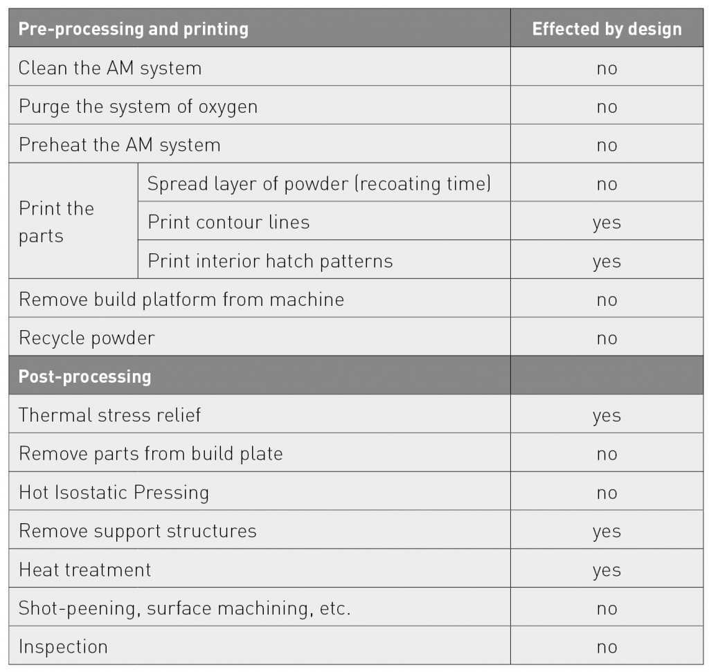
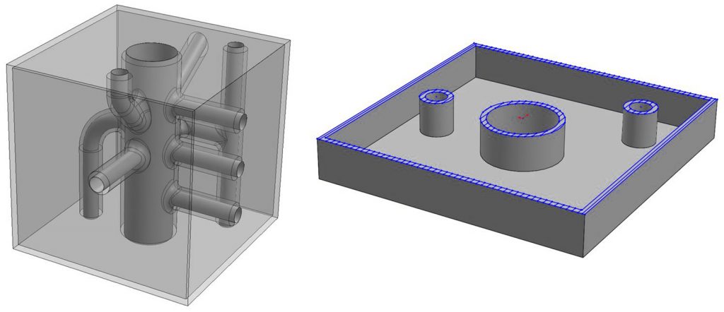
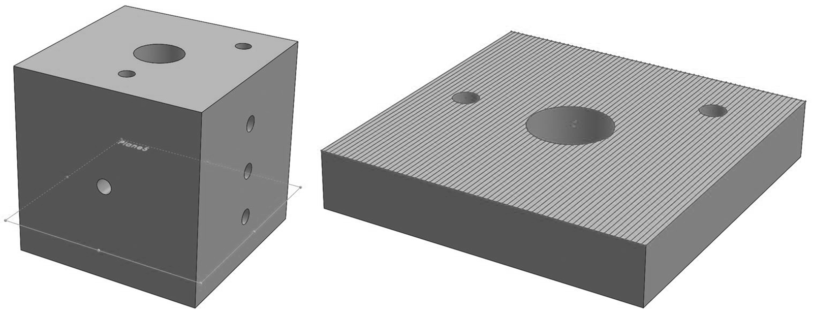
Suppose a hydraulic manifold is designed for conventional CNC machining. It may consist of a metal block into which many connecting holes are drilled to form interconnecting channels. These channels allow hydraulic fluid to flow to the ports, with valves and pressure sensors attached. The only way to conventionally manufacture internal connecting channels inside the block is to drill holes through from the outside of the block, and then plug them so that only the internal channels remain. If one were to produce such a manifold using AM, a layer of the manifold would look similar to a filled square with a few holes in it, as shown in Fig. 1.

Here, the scanning hatch pattern for each layer requires a long scanning distance. If the manifold measures 100 x 100 mm, and the hatch spacing is set to 0.1 mm, each square will require approximately 100 meters of scanning. In other words, the beam has to travel over 100 meters to create that layer of the part. To relate this to part cost, if the beam is travelling at 330 mm per second, it will take 300 seconds (five minutes), to hatch a layer of the part. In machine time, it would cost $5.41 at $65 per hour.
Reducing material use
In contrast, if the bulk of the material is removed from the same part by ‘shelling’ it to a specified wall thickness, the amount of scanning is greatly reduced, resulting in a faster print time (Fig. 2). If shell thickness is set to 2 mm and the same hatch spacing parameters are used as before, the total scan distance is about 4.5 meters — a scan distance reduction of more than 95%. If the beam is travelling at 330 mm per second, it will take 13.6 seconds to hatch that layer of the part; $0.24 in machine running cost
When the shelled part is finished, the internal cavities will be filled with unmelted powder, which can remain if weight is not an issue. If weight is a concern, openings can be added to provide access for removing the powder. If weight is not an issue, the interior of the part can be filled with support structures.
It is helpful to minimise large volumes of solid material when designing for AM. Similar to a consistent wall thickness in injection moulding, large masses of material usually offer little engineering advantage. They are likely to cause warping of the part and induce residual stress. In addition, they can greatly extend build times. Design techniques are available for eliminating large masses of material, including the shelling method described previously. Another is to fill solid regions with a honey-comb lattice, or porous build structure. Avoiding large masses of material can also reduce thermal stress relief (heat treatment) time. If a part has no large masses of material with a mostly regular wall thickness, it will contain less residual stress from the build process, thus reducing heat treatment time.

Build times and support structures
From a build time perspective, it is best to produce a part in an orientation in which build height is at its lowest. This will result in the fewest number of layers and the fastest build time. Build orientation also plays a role in the mechanical properties of a part, geometric accuracy, surface finish and support material, so these also need to be considered.
One of the important goals in designing for metal AM is to reduce the amount of support material required to build a part. With metal AM, support material is used to anchor the part to the build platform and help support and secure overhanging features. Most importantly, the support material transfers heat away from the part to minimise thermal distortion. In particular, it is important to avoid support material in any internal features, such as inside the manifold channels, as this can be difficult or impossible to remove.
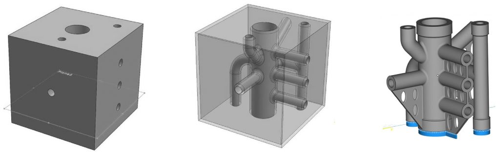
Fig. 3 shows three versions of the block manifold. On the left is a conventionally machined and drilled design, in the centre the manifold is shelled and designed for AM, but with substantial support structures, and on the right is a fully optimised design. The third version can be built with little support material, which anchors it to the build plate. This small amount of support material is relatively easy to remove. Table 2 shows the differing time, cost and weight of the three designs.
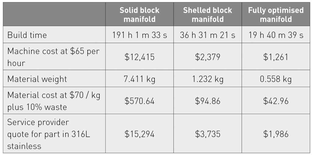
The manifold example illustrates the impact that machine cost has on AM part production. It is the most significant factor in overall cost, and can be reduced significantly by avoiding large masses of material and the extended hatching times that come as a result. It quantifiably demonstrates that even a simple strategy of replacing large masses of material with even wall thickness shells can have a substantial impact.
Authors
Olaf Diegel and Terry Wohlers Wohlers Associates, Inc.
Fort Collins
Colorado 80525
USA
LAST MONTH’S MOST-READ ARTICLES


