Case Study: Cooling channels for material testing applications using Laser Powder Bed Fusion
Additive Manufacturing continues to gain a reputation as a key technology that will have a major impact on all aspects of mechanical engineering. Under the guidance of Major Ryan O’Hara, the United States Air Force’s (USAF) Air Force Institute of Technology (AFIT), based in Dayton, Ohio, has expanded its AM-focused education and R&D capabilities with the purchase of a Laser Powder Bed Fusion system from Germany’s Concept Laser. In the following article, AFIT’s Benjamin Doane and colleagues highlight work done at the institute to develop AM testbed components to support a high-temperature testing programme. [First published in Metal AM Vol. 4 No. 1, Spring 2018 | 15 minute read | View on Issuu | Download PDF]
The Air Force Institute of Technology, the United States Air Force’s graduate school, recently purchased and installed its first metal Additive Manufacturing system. The addition of this Laser Powder Bed Fusion (LBPF) machine complements AFIT’s long history of using polymer-based Additive Manufacturing to enable defence-focused graduate research. As part of AFIT’s graduate education mission, it is imperative that students are able to work with cutting edge manufacturing technologies. By utilising the enhanced design benefits of AM, these graduate research students become familiar with the nuances of metal and polymer AM processes. As the private sector rapidly embraces AM, it is vital that government organisations focus on the newest developments in AM processes in order to successfully implement them in current defence applications.
AFIT researchers believe that a hands-on approach to gaining this understanding is required to fully realise the implications of AM technologies. AFIT is focused on process parameter optimisation, material property quantification and qualification, mechanical testing and functional implementation of metal AM. In this article, AFIT researchers present how metal AM components can improve upon currently implemented technology used in mechanical testing.

Motivation for the implementation of AM
In recent years, Additive Manufacturing has been adopted by many industries to enhance their ability to bring innovation to their product offerings. The aerospace and automotive industries now incorporate AM processes to enable capabilities in their products which were previously unfeasible. It has been shown that AM is an excellent technology for adding internal structures in parts to increase heat transfer [1]. While AM allows for parts with novel capabilities that cannot be replicated with traditional production methods, the consistency of the parts built cannot be guaranteed. It has been shown that AM materials’ properties may vary not only from machine to machine, but also from build to build [2]. It is crucial that these variations be identified and quantified. The tests used to quantify this variance include measuring a material’s mechanical performance in a variety of standard testing conditions. Material Test Systems (MTS) machines are used to perform these mechanical tests.
High-temperature mechanical creep testing
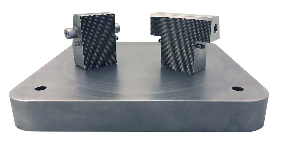
The Air Force Institute of Technology is particularly interested in the high temperature creep performance of Inconel 718 (IN718). Due to the high temperatures (700°C) associated with this testing, the standard steel wedges that are employed to grip tensile specimens have fractured. To enable high temperature mechanical creep testing, AFIT researchers designed wedges for production by Additive Manufacturing with internal cooling channels to maximise their performance compared to their traditional subtractive counterparts.
AM has enabled an active cooling system that reduces the wedge’s thermal stresses and prevents wedge fracture during creep testing. These wedges were successfully manufactured at AFIT using IN718. Commercial off-the-shelf Computational Fluid Dynamics (CFD) software and thermal imaging methods were used to analyse, compare and validate the performance of the AM optimised wedge versus a conventional wedge. The findings demonstrate that the AM wedge design is three times more efficient at heat transfer compared to the conventional wedge design.

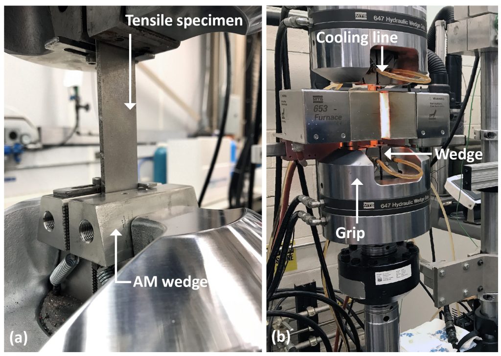
Tension and high temperature creep material tests have traditionally been completed with stainless steel grips in an MTS machine. During creep tests, the MTS machine uses two pairs of wedges to grip a tensile specimen (Fig. 2a). Simultaneously, a furnace heats the tensile specimen and a chiller flows coolant through the wedges to prevent fracture (Fig. 2b). Nevertheless, the coolant has failed to prevent wedge fracture during these tests. This study explores the effects of adding cooling channels to these mechanical wedges using Additive Manufacturing.
CFD analysis and thermal imaging have been used to compare the conventional wedge design with the AM optimised design. Theoretically, the cooling channels in the AM design will increase heat transfer and prevent wedge fracture during creep testing.
Design for AM
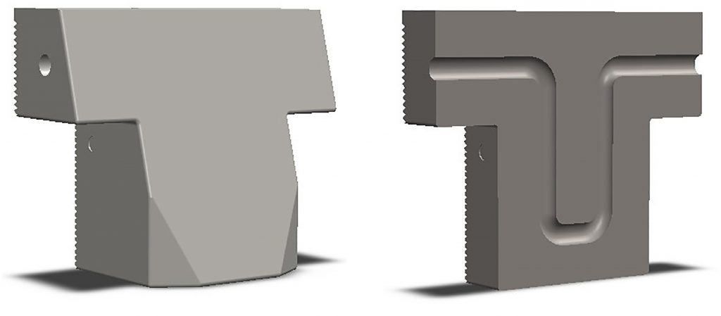
This project consisted of two design cycles. The initial design contained a triple loop interior cooling channel with a 3.0 mm diameter. However, the narrow channel in this design made it difficult to remove the powder from the interior and this powder subsequently prevented fluid flow (Fig. 3).
In the second and final iteration, a single loop replaced the triple loop and the diameter of the channel was increased to 5.0 mm. The build orientation was optimised to minimise the use of supports. This design allowed the powder to be removed from the interior channel and provided adequate fluid flow for experimental testing (Fig. 4).
Computational fluid dynamics to determine heat removal
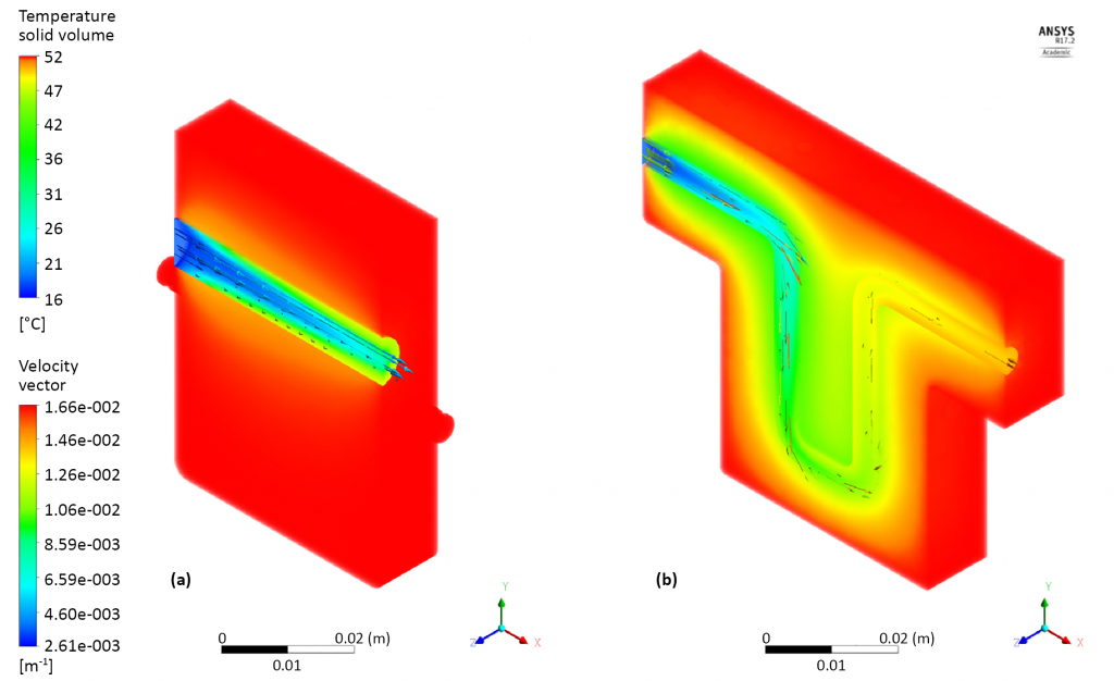
CFD analysis provides qualitative and quantitative prediction of fluid flows and thermal performance by means of mathematical modelling and numerical methods, based on fundamental momentum, energy and continuity equations. The ANSYS™ CFD package was utilised for the computational section of this research. The AM and conventional design files were meshed and imported into ANSYS™ Fluent. Flow conditions were characterised for internal pipe flow using the Reynolds number equation [3]. The Reynolds number identified whether the flow type was laminar or turbulent, which in turn determined the flow equation required for the CFD model. For the purpose of this research, fluid flow was found to be turbulent from the inlet [4] for both models. Table 1 shows the input parameters used in the CFD model. A no-slip condition is applied, which forces the fluid to have zero velocity relative to the solid boundary of the cooling passages.Utilising the results from the CFD analysis (Fig. 5), the total enthalpy at the inlet and outlet of each model was accounted for, where enthalpy is defined as the measurement of energy in a thermodynamic system. This is equal to the internal energy of the system plus the product of pressure and volume [5]. The change in total enthalpy indicates the amount of heat being removed from the system. With this information a quantitative comparison between the conventional and additive designs is possible.
Wedge fabrication using Laser Powder Bed Fusion
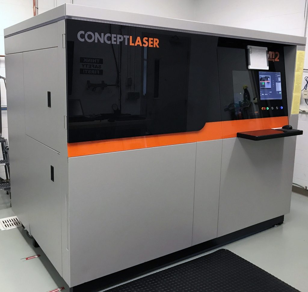
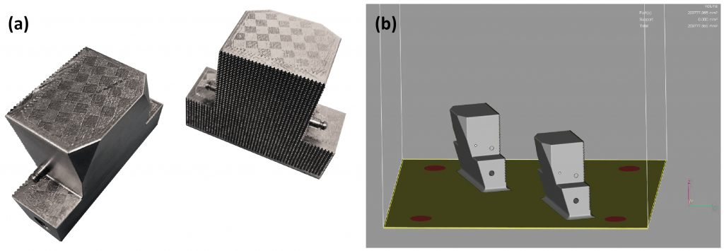
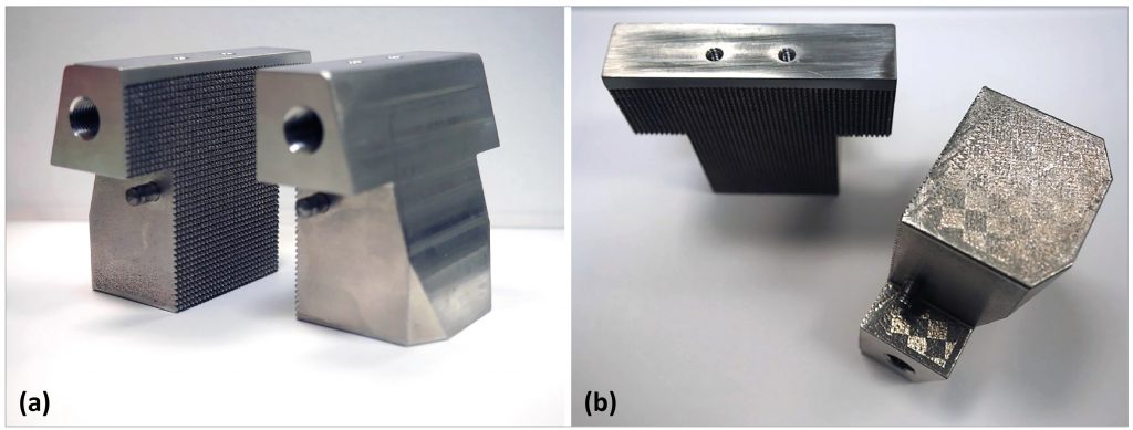
The AM wedge was printed at AFIT’s Additive Manufacturing Laboratory using an M2 Cusing metal Additive Manufacturing system from Concept Laser GmbH (Fig. 6). The LPBF process used in the M2 employs a combination of parameters to control the spot size, power and speed of the laser, which ultimately affect the surface finish and density of the printed parts. These laser settings vary depending on the metal powder being used. The laser scan strategy used for this project was the standard island and skin core parameters developed by Concept Laser GmbH for use with IN718. Fig. 7a shows the island scan pattern strategy on the finished part. This strategy randomly exposes sections of powder in a checkered pattern. Furthermore, the skin core strategy decreases print time by exposing the outer contours (the skin) on every layer and then the surface area (the core) of the part every alternate layer [6]. For this build, the print layer height was set at 0.025 mm with a powder dosage of 0.0375 mm per layer. Materialise Magics was used as the slicing software. Build orientation during the print using Magics software is visible in Fig. 7b.
A filleted 4 mm offset, as seen in Fig. 7a, was added to the base of the part to allow for extra space for post-processing purposes, as well as to provide additional material to assist with heat transfer and build plate adhesion. A one-inch thick steel plate was used as the build platform. All post-processing was completed at AFIT’s Model Fabrication Shop. Post-processing included using a wire-cut electrical discharge machine to remove the parts from the build platform, grinding critical surfaces, tapping and threading holes for attachments.
Experimental testing
The AM wedges were successfully utilised during a creep test at AFIT. The wedges were installed in a 22 KIP 810 MTS® machine on the lower grips (Fig. 2). An attached MTS 653 furnace was used as the heat source, deionised water was selected as the coolant and the grip pressure was set at 6.8 MPa (1000 psi). A constant force of 1000 N was applied to the tensile specimen and steady state was reached with a furnace temperature of 700°C, coolant flow velocity of 13.5 mL/sec and a coolant temperature of 22°C. A FLIR® SC7650 infrared camera was utilised to map the thermal profile of the AM and conventional wedge sets.

Regions of Interest (ROI) on the visible surface of the wedge sets were created using the FLIR® ExaminIR Pro software. The ROI was replicated on both wedge designs and the thermal images were acquired separately. However, it was observed that both the AM and conventional wedge had high percentages of IR reflection, due to the emissivity of the metal surface. Additionally, due to the setup of the MTS machine and attached furnace, it was difficult to observe the grip surface that was expected to receive the highest amount of heat transfer. Nevertheless, the initial experimental setup confirmed the viability of the AM design for use in high temperature creep tests on MTS machines.
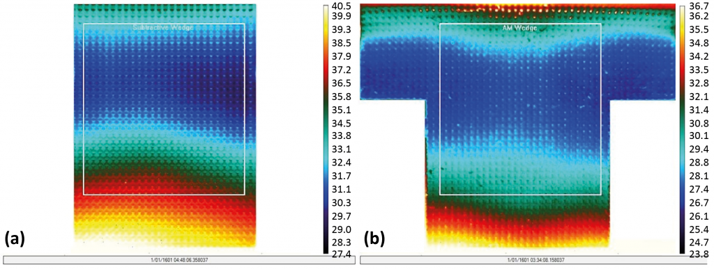
In order to accurately map the thermal profile of the wedges with an IR camera, the wedges were coated with Aeroglaze Z306. Aeroglaze Z306 has an emissivity value of 0.91, which means that it will emit most of the heat it absorbs. Coating the wedges mitigated the temperature reading errors caused by the IN718’s high IR reflectivity. Next, in order to view the grip surface most likely to experience the greatest amount of cooling, the wedges were removed from the MTS machine and a halogen lamp was used as an external heat source to simulate the furnace. Single AM and conventional wedges coated in Aeroglaze Z306 were heated separately with a halogen lamp, while coolant was passed through the interior channels from left to right at a constant velocity of 13.5 mL/sec and temperature of 16°C. Once steady state was reached, thermal images were acquired with a FLIR® SC7650 for both designs (Fig. 8).
Results and conclusions
CFD analysis revealed a higher enthalpy change in the AM design. Conduction and forced convections are the dominating heat transfer phenomena as any radiation effect is considered minimal. The forced convection between the fluid flow throughout the body of the wedge is represented using a heat transfer convection equation. As the water flows from the inlet to the outlet in a regenerative cycle, heat energy is transferred from the solid to liquid and taken out of the wedge by the presence of bulk fluid motion [7]. ANSYS™ analysis showed that the AM wedge design was more effective at transferring heat compared with the conventional wedge design and caused a change in enthalpy that was 2.87 times greater than the conventional design. The AM model had a total enthalpy change of 2.017 kJ/kg, while the conventional model had a total enthalpy change of 703 kJ/kg (Table 2).

The thermal images taken with the IR camera indicated that the cooling channel in the AM design removed more heat compared with the conventional design, resulting in a lower average temperature. The temperature of the conventional ROI had an overall average temperature of 31.7°C, while the AM ROI had an average temperature of 27.7°C.
Future work in this area could explore more complex interior channels, such as helical coils with protrusions in the channel that would cause a more turbulent environment and, in turn, increase fluid contact time and heat transfer. These designs could be scaled and applied to similar applications that require fluid cooling channels.
Acknowledgements
The authors would like to thank the AFIT model shop for their continued support through our numerous additive design adventures, as well as Travis Shelton and Gregory Cobb for their endless devotion to the metal arts.
Authors
B Doane, K Liu, R O’Hara and C Hartsfield
Aeronautics and Astronautics
Air Force Institute of Technology
Dayton, OH 45433
USA
Email: [email protected]
www.afit.edu
References
[1] Ugolotti M, Sharma M, Williams Z, Owen M, Balachandar S, Ouwerkerk J, et al. Cooling system for 0.1 kN thrust micro- engines: Concept design using Additive Manufacturing. In: 58th AIAA/ASCE/AHS/ASC Structures, Structural Dynamics, and Materials Conference; 2017. p. 1–20.
[2] Yadollahi A, Shamsaei N. Additive Manufacturing of fatigue resistant materials: Challenges and opportunities. International Journal of Fatigue 2017;98(Supplement C):14 – 31.
[3] Neale A, Derome D, Blocken B, Carmeliet J. CFD calculation of convective heat transfer coefficients and validation – Part 2: Turbulent flow. Kyoto; 2006.
[4] White FM. Viscous Fluid Flow. 3rd ed. New York: McGraw-Hill; 2006.p. 426–427.
[5] Zemansky MW, Dittman RH. Heat and thermodynamics: an intermediate textbook. McGraw-Hill New York; 1968.
[6] Carter LN, Martin C, Withers PJ, Attallah MM. The influence of the laser scan strategy on grain structure and cracking behavior in SLM powder-bed fabricated nickel superalloy. Journal of Alloys and Compounds 2014;615(Supplement C):338–347.
[7] Incropera FP, Dewitt DP, Bergman TL, Lavine AS. Principles of heat and mass transfer. 7th ed. Hoboken, New Jersey: John Wiley & Sons, Inc.; 2003.

LAST MONTH’S MOST-READ ARTICLES