


Additive Manufacturing at World PM2016: Advances in the processing of aluminium and magnesium alloys
The Additive Manufacturing of light alloys was the focus of three separate technical sessions at the World PM2016 Congress, held in Hamburg, Germany, from 9-13 October, 2016. The event, which was organised by the European Powder Metallurgy Association (EPMA), covered all aspects of metal powder processing technologies. This report reviews three of the key papers from these sessions, two relating to the AM of aluminium alloys and the third to the AM of a magnesium alloy. [First published in Metal AM Vol. 2 No. 4, Winter 2016 | 20 minute read | View on Issuu | Download PDF]
Investigations on aging behaviour of aluminium powders during a lifetime simulation for LBM
One of the seven designated Keynote Papers within the full PM2016 World Congress programme was presented by Dominik Bauer (Airbus Innovations, Munich, Germany). The paper was co-authored by Elisabeth Schwarzenboeck, Norbert Schupp and Frank Palm (also Airbus Innovations) and Ina Ludwig and Gerd Witt (University of Duisburg, Germany) [1].
The issues addressed, which act as current impediments to the building of aluminium alloy parts by AM techniques, include the susceptibility of these materials to hydrogen embrittlement and oxidation. Therefore, this reported work was motivated by the need to avoid the contamination of atomised aluminium alloy powders by oxygen and hydrogen during powder production, handling and storage, processing by powder bed Laser Beam Melting (LBM) and recycling of unmelted powder from the bed after the part build run.

Information from the published literature indicates that environmental conditions, especially temperature, humidity and pressure, play an important role in the appearance and composition of oxide and hydroxide layers on aluminium powders and these, in turn, affect defect formation in LBM parts. The effects of long term exposure to humidity must therefore be understood in more detail. In order to achieve high levels of mechanical properties in built parts, it is important to guarantee reproducible and high quality powder production, storage and processing.
Aluminium alloy powders produced and handled under dry conditions would be expected to be covered by a passive Al2O3 layer a few nanometres thick. However, in humid conditions, water reacts with the alumina layer, leading to AlOOH generation. Finally, the hydroxide is reduced by aluminium, generating hydrogen bubbles at the metal/oxide interface. As soon as the hydrogen pressure in the gas bubbles exceeds the oxide’s tensile strength, the passive layer fractures, exposing fresh reactive metal and further promoting surface layer formation.
Two different atomised powder grades were investigated in the study, the alloys AlSi7Mg0.6 (P2) and AlSi10Mg0.45 (P1). These powders were produced by Electrode Induction Melting Gas Atomisation (EIGA) with an inert gas as the atomising medium. All atomised powders were separated by air and then sieved to give a particle size distribution between 20 and 63 µm.

The chemical compositions of powders P2 and P1 are shown in Table 1 and these lie within the allowable limits defined in ENAC–43400 and ENAC–42200 respectively. The elemental analysis was carried out using Inductively Coupled Plasma Optical Emission Spectroscopy (ICP-OES), the silicon content was examined by gravimetric measurement and carrier gas hot extraction was used to analyse the amount of oxygen contamination in the powder. Both powders complied with the authors’ observations from earlier work that a high-quality LBM powder must be covered by a thin oxide layer and that the oxygen content should not be higher than 500 ppm.
![Table 1 Analysed chemical compositions of powders P2 and P1 [1]](http://www.metal-am.com/wp-content/uploads/sites/4/2016/12/t01-1024x697.jpg)
The values for particle size distribution were measured by laser diffraction and are shown in Table 2. Powder P1 had higher values for D10, D50 and D90, compared with powder P2. SEM observations indicated that both powder types were predominantly spherical in shape, but that powder P2 exhibited higher levels of agglomeration and satelliting.
![Table 2 Particle size distributions of the investigated powders [1]](http://www.metal-am.com/wp-content/uploads/sites/4/2016/12/t02-1024x183.jpg)
Powder aging due to handling and LBM process simulation was assessed using a climate chamber, comprising containers equipped with a moisture barrier. A salt solution in the container provides a nearly constant value of the moisture content for defined temperatures. To create defined moisture levels, potassium chloride and magnesium chloride were used for the aging investigations.
The chosen parameters for the series of aging trials are shown in Table 3. Parameter set A1 was chosen to mimic typical ambient conditions in the German summer period. Considering the LBM process, the temperature of the atmosphere in the build chamber climbs to ~50°C during a build job. Consequently, the parameter sets A3 to A6 in Table 3 were chosen to bracket this approximate temperature. The powder P1 (AlSi10Mg) was used for these aging simulations.
![Table 3 Parameters for the aging series of AlSi10Mg powder [1]](http://www.metal-am.com/wp-content/uploads/sites/4/2016/12/t03-1024x444.jpg)
SEM observations of the powder after the A1parameter set showed no visible differences from the starting powder and the same was true of the material subjected to parameter sets A2 and A3. The SEM micrographs in Fig. 2 show the results for aging parameter set A4. Around this parameter set, all particles show characteristics such as whisker growth on their surface. Fig. 2b shows, for a higher magnification around the marked area, a puckered structure for the surface and whiskers on the surface. Fig. 2c shows whiskers that have grown out from the particle surface and are thinner nearer to the surface.
![Fig. 2 SEMs of powder aged at parameter set A4 [1]](http://www.metal-am.com/wp-content/uploads/sites/4/2016/12/02-440x1024.jpg)
For the parameter set A5, Figs. 3a-c show that the formed whiskers are thinner and, compared with parameter set A4, they are formed homogenously and distributed evenly. The duration of aging for parameter set A5 was longer, but at a lower temperature and, because of this, the growth of the whiskers and grains was slower. Overall, it was concluded from these trials that the influences of humidity level and temperature on whisker growth are more significant than that of exposure time.
![Fig. 3 SEMs of powder aged at parameter set A5 [1]](http://www.metal-am.com/wp-content/uploads/sites/4/2016/12/03-440x1024.jpg)
The final powder characteristic assessed was flowability and this characteristic was dynamically measured with a Revolution Powder Analyser. In this test method, 100 ml of powder is filled in a drum between two glass fronts. Due to the rotation of the drum, the powder begins to form avalanches. These avalanches are then described by the average angle, as an indicator for the powder flowability. To ensure an initial homogenous state of each powder, 315 avalanches are generated before the test series. Then, each test series is carried with five test cycles, each with 150 avalanches. For each powder, the avalanche angle and avalanche time are measured and average angles and times are calculated based on all the test results.

The flowabilities of the P2 powder (AlSi7Mg0.6) were measured for the various conditions shown in Table 4. The climate conditions were chosen to generate no changes on the surface, such as the growth of whiskers, and to avoid oxidation of the particles. Powder samples C1, C3 and C5 were exposed to the same starting climate, followed by flowability measurement. Powder samples C2 and C6 were additionally exposed for 72 hours at room temperature and a humidity of ~85% rH. For powder samples C4 and C6, the powders had been dried under vacuum at a defined temperature of 25°C.
![Table 4 Climate atmosphere investigations for flowability of powder P2 [1]](http://www.metal-am.com/wp-content/uploads/sites/4/2016/12/t04-1024x436.jpg)
Fig. 4 shows the flowability test results for the powder samples C1 to C6. As anticipated, samples C1, C3 and C5 showed virtually the same values for average avalanche angle and average avalanche time. For the increasing humidity arising from condition C2 compared with C1, the avalanche angle and time increased significantly. This can be related to a higher agglomeration rate, caused by the higher moisture content and hydrogen bond. Due to the high number of fine particles, this powder material is sensitive to agglomeration. The average avalanche angle decreases slightly from condition C3 to C4, where the powder was only dried from the starting condition without exposure to a higher humidity. Powder condition C6 was dried after exposure to a higher humidity. Compared to condition C5, the average avalanche angle and average avalanche time were both lower and the flowability increased. The results of this investigation showed that the average avalanche time is more sensitive to moisture than the average avalanche angle.
![Fig. 4 Powder flowability measurements for powder P2 [1]](http://www.metal-am.com/wp-content/uploads/sites/4/2016/12/04-1024x485.jpg)
From these tests, the authors concluded that there is a potential to dry the powder and, consequently, recondition the flowability. Drying of the powder was also expected to reduce the agglomeration rate and to achieve a higher bulk density in the deposited powder.
Finally, the authors indicated that further work should be directed at investigating the direct influence of the various powder conditions on mechanical properties. There is a possibility that, for sensitive powders, defined storage conditions and an expiry date may have to be established.
Microstructural and mechanical properties of Al-Si-Ni alloy produced by Direct Metal Laser Sintering
In the study presented by Alberta Aversa (Politecnico di Torino, Italy) and co-authored by Sara Biamino, Paolo Fino and Matteo Pavese (also Politecnico di Torino) and Massimo Lorusso, Francesco Trevisan, Diego Manfredi, Flaviana Calignano and Elisa Ambrosio (Istituto Italiano di Tecnologia, Italy) the effects of the introduction of nickel on the microstructure and mechanical properties of aluminium alloy components, built by Direct Metal Laser Sintering (DMLS) were investigated [2].
The laser powder bed processing of aluminium based powder faces challenges related to a number of its physical characteristics, such as high reflectivity, high thermal conductivity and low powder flowability. From the broad range of available aluminium alloys, the AlSi10Mg casting alloy has emerged as the most attractive for AM processing, because of its high fluidity in the molten state and its narrow solidification range due to its near-eutectic composition.

The extremely high cooling rates that arise during laser powder bed processing (~106 K/s) allow the creation of fine and new microstructures and hence unique mechanical properties. To-date, however, there has been limited research activity aimed at taking advantage of this fast cooling to create novel microstructures, such as supersaturated solid solutions, metastable intermetallic phases and metallic glasses. Published studies, however, have reported that high strength can be achieved by the introduction of transition metals, such as nickel, to rapidly solidified Al-Si alloys. Therefore, this reported study was aimed at investigating the microstructure and mechanical properties of Al-Si-Ni samples processed by laser powder bed fusion.
An EOS M270 Xtended system was used to build all samples. This system uses an argon atmosphere with oxygen content lower than 0.1% and an ytterbium fibre laser with a power up to 200 W to melt thin layers of metal powder. An AlSi10Mg gas atomised powder, supplied by EOS GmbH, was mixed with a spherical pure nickel powder. The nominal chemical compositions of the powder batches are reported in Table 5. The mixing ratio for the Al-Si-Ni material was chosen to obtain a chemical composition close to the ternary eutectic (567°C at 4.9 wt.% Ni and 10.98 wt.% Si).
![Table 5 Nominal chemical compositions of the powder batches [2]](http://www.metal-am.com/wp-content/uploads/sites/4/2016/12/t05-1024x136.jpg)
The powders were dry mixed in ceramic jars for 48 hours without any grinding medium and were sieved using a 230 mesh sieve (63 μm) to eliminate the larger powder fractions. Cubic samples with 10 mm length were built using the EOS stripe scanning strategy by varying the main building parameters laser power (P) scan speed (v) hatching distance (hd) and stripe length (s) on a 100°C platform using a 30 μm layer thickness. The building parameters were varied in the range shown in Table 6.
![Table 6 Range of build parameters used [2]](http://www.metal-am.com/wp-content/uploads/sites/4/2016/12/t06-1024x290.jpg)
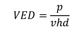
To select the most suitable building parameters, two main approaches were used. Firstly, the Volumetric Energy Density (VED) parameter, calculated using the equation below, was employed to select the minimum value that can generate a low porosity level.
Secondly, the Taguchi statistical approach was used to understand the effect of each building parameter on the consolidation. For the various parameters, the signal to noise values (SN) were calculated by means of the following equation, using the porosity as the quality factor:
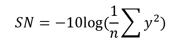
where y are the porosity values and n the number of trials.
The signal to noise values, based on the porosity data, are reported in Fig. 5. It is evident that P, v and hd have the most significant effects on sample consolidation. The porosity versus VED graph for the Al-Si-Ni samples is shown in Fig. 6. This material shows the expected trend, in that higher VED values lead to lower porosity levels. This type of trend is observed in most materials processed by powder bed fusion technology.
![Fig. 5 Signal to noise values [2]](http://www.metal-am.com/wp-content/uploads/sites/4/2016/12/05-1024x776.jpg)
![Fig. 6 Porosity versus VED graph for the Al-Si-Ni samples [2]](http://www.metal-am.com/wp-content/uploads/sites/4/2016/12/06-1024x591.jpg)
It was apparent that the introduction of nickel does not strongly influence the consolidation phenomena. In view of this and in order to have a more reliable comparison with the standard aluminium alloy, the build parameters were chosen to be the same as for the standard AlSi10Mg (P=195 W, v=800 mm/s, hd=0,17 mm, S=5 mm).
![Fig. 7 Optical micrograph of the Al-Si-Ni sample built with the optimised parameters [2]](http://www.metal-am.com/wp-content/uploads/sites/4/2016/12/07-1024x693.jpg)
The optical micrograph of the Al-Si-Ni sample cross section, shown in Fig. 7, demonstrates that the powder bed fusion process can produce dense and crack-free parts. A few pores and some precipitates could be recognised. The XRD pattern, shown in Fig. 8, indicates that the precipitates could be Al3Ni. From Fig. 8, it can be also noted that, for both powder types, most of the silicon is contained in solid solution in the aluminium phase.
![Fig. 8 XRD patterns of a) an Al-Si-Ni and b) an AlSi10Mg sample [2]](http://www.metal-am.com/wp-content/uploads/sites/4/2016/12/08-777x1024.jpg)
The FESEM micrographs of the samples, shown in Fig. 9, highlight the fact that an extremely fine microstructure was produced. The size and the distribution of the precipitates do not follow any pattern correlated with scanning strategy, suggesting that they could be due to the mixing process rather than to a build process issue. The EDX analyses (Table 7) indicate that, even in the presence of some Al3Ni agglomerates, the phenomena that arise in the melt pool, such as Marangoni flow and the recoil pressure effect, allow the dispersion of most of the nickel content within the aluminium alloy.
![Table 7 EDX data corresponding to the points shown in Fig. 8a [2]](http://www.metal-am.com/wp-content/uploads/sites/4/2016/12/t07-1024x205.jpg)
![Fig. 9 FESEM micrographs of the Al-Si-Ni sample cross section [2]](http://www.metal-am.com/wp-content/uploads/sites/4/2016/12/09-1024x342.jpg)
Vickers hardness tests, on the samples built with the optimised parameters, showed that the introduction of nickel into the alloy strongly increased the hardness level, from around 136 Hv to 180 Hv.
AM of magnesium alloy powders: Elektron® MAP+43 via Laser Powder Bed Fusion and Directed Energy Deposition
The final paper in this review moves from aluminium to magnesium alloys. Rajiv Tandon (Magnesium Elektron Powders, USA), Todd Palmer (Pennsylvania State University, USA) and Matthias Gieseke, Christian Noelke and Stefan Kaierle (all Laser Zentrum Hannover, Germany) reported on a study of the Additive Manufacturing, via both laser powder bed fusion and directed energy deposition, of the Magnesium Elektron powder grade, Elektron MAP+43, which was specifically developed for AM processing [3].
The low evaporation temperature and melting point of magnesium, coupled with its high vapour pressure, makes it challenging to process. The magnesium powder, used in both powder bed fusion and directed energy deposition processes, must be passivated during production to allow for safe handling. The resulting stable magnesium oxide layer on the surface of powder inhibits the wetting process and, therefore, influences the processing window.
Previously reported work on directed energy deposition using the rare earth containing alloy Elektron®MAP+43 has shown that it is possible to achieve a yield strength of 170 MPa, an ultimate tensile strength of 255 MPa and 7.9% elongation. These property levels compare favourably with those of a cast WE43B alloy in a T-6 heat treated condition.
The aim of the currently reported study was to present a few key aspects of the processing of rare earth containing alloy Elektron®MAP+43 using the Directed Energy Deposition (DED) and powder bed fusion processes.
Directed Energy Deposition
Directed Energy Deposition studies used a gas atomised spherical Elektron® MAP+43 powder (D10 = 50 μm, D50 =83 μm, D90 =133 μm). The deposition experiments were performed on a custom fabricated deposition system with build dimensions of up to 1000 mm L x 300 mm W x 450 mm H. The power source was an ytterbium fibre laser with a wavelength ranging from 1070 to 1100 nm. Powder was delivered using a custom designed four nozzle system. The substrate was placed approximately 10 mm from the nozzles. At this location, the laser beam was in a defocused position and had a measured beam diameter of approximately 4 mm. The process parameters investigated included varying the laser power between 1750 and 2250 W, travel speed between 0.85 and 1.27 cm/s, nozzle gas flow between 100 and 200 l/min and layer height step between 0.038 and 0.1 cm. The powder flow rate was set at 5 g/ min and the chamber oxygen level was between 80 and 110 ppm.
In this initial development work, five-pass wide and six-layer high deposits were fabricated as shown in Figs. 10a and b. The substrate used was wrought Elektron® 43. These builds were assessed in terms of microhardness, microstructure, grain size and porosity. The test results were ultimately used to select the processing parameters for building the final test geometry, which was 15.24 cm long, 5.08 cm high and 1.27 cm thick, as shown in Fig. 10c. The selected parameters used a laser power of 2250 W, travel speed of 1.06 cm/s and a step height of 0.062 cm. Some of the samples shown in Fig. 10c were Hot Isostatically Pressed following deposition. Tensile test specimens were machined in both the horizontal and vertical orientations and were in various conditions, including as-deposited, as-deposited + T5 (artificial aging at 250°C for 16 h), and as-deposited + T6 (a solutionising treatment at 525°C for 2 h followed by aging at 250°C for 16 h).
![Fig. 10 Test geometry for selecting process parameters (a) and (b), final test geometry (c) [3]](http://www.metal-am.com/wp-content/uploads/sites/4/2016/12/10-1024x193.jpg)
A high as-deposited relative density of >99% of theoretical was achieved by optimisation of the deposition parameters. As compared to the starting powder grain size of approximately 2 μm, the average grain size in the deposited samples ranged from 8 μm to 9.6 μm. The micro hardness of the deposited layers ranged from 76 HVN (Hardness Vickers Number) to 81 HVN (versus a micro hardness of 96 HVN for the starting powder). There was no gradient in the micro hardness in the vertical build direction and the microstructure consisted of small repeating isolated clusters of pores, as shown in Fig. 11. These pores were present mainly in the overlap zones between successive passes. The best results were obtained using a laser power of 2250 W with a scan speed of 1.06 cm/s and an overlap of 0.20 cm. Under these conditions, an optimum combination of small grain size (8 μm), small pore volume (0.70%) and high as-deposited micro hardness (81 HVN) was obtained.
![Fig. 11 Typical cross-section of an as-deposited sample showing overlapping layers, micro hardness variation along three build planes and microstructure with fine grain size and pore clusters [3]](http://www.metal-am.com/wp-content/uploads/sites/4/2016/12/11-1024x236.jpg)
The mechanical properties of the as-deposited, HIPed and heat treated samples are shown in Fig. 12. HIPing increased the overall ductility together with a slight improvement in UTS. The artificial age T-5 cycle did not result in any significant change to the as-deposited properties. In comparison, the T-6 treatment restored the aging response and improved yield, UTS and elongation. The overall mechanical properties obtained in the study compared favourably with those typical of a cast WE43B alloy.
![Fig. 12 Mechanical properties of Elektron®MAP+43 produced via directed energy deposition [3]](http://www.metal-am.com/wp-content/uploads/sites/4/2016/12/12-1024x336.jpg)
The HIPed + T6 heat treated microstructure is shown in Fig.13. No pores were observed in the HIPed samples. The elemental scan maps show the presence of Y, O and Nd. The yttrium rich phase did not completely dissolve in the 525°C/2 h solutionising cycle. It should be noted that the starting powder used in this investigation was passivated for safe handling and, therefore, the presence of Y2O3 was expected. In addition, yttrium has a greater affinity for oxygen than magnesium and it is possible that some yttrium oxide may have formed during the melting process through the reduction of MgO.
![Fig. 13 Microstructure and elemental scan maps of a Hot Isostatically Pressed and heat-treated sample [3]](http://www.metal-am.com/wp-content/uploads/sites/4/2016/12/13-1024x396.jpg)
During the investigation, magnesium vaporisation and powder dust was created inside the deposition chamber. The low density of magnesium powder could be a factor in dust creation and on-going efforts are being aimed at mitigating this effect, including studying the effects of optimised particle size distributions. Another on-going area of investigation is to reduce the occurrence of pore clusters, as shown in Fig. 11. Early results indicate that, by employing secondary re-melting techniques at lower power settings ranging from 500 W to 1500 W (between successive passes), it is possible to minimise as-deposited microporosity.
Although a relatively simple rectangular geometry with an overall volume of about 400 cm3 was deposited in these studies, the resulting properties have given the authors confidence that it should be possible to scale the DED process to more complex shapes.
Laser Powder Bed Fusion
Laser Powder Bed Fusion investigations were performed on an SLM 125HL machine with a 100 W fibre laser and a focus diameter of 70 μm, using gas-atomised Elektron®MAP+43 powder with a particle size distribution D10= 22.5 μm, D50=31 μm and D90=45 μm.
A 50 x 50 x 50 mm3 build volume was used along with high purity Ar as shielding gas. Parameter studies on varying laser power, scan speed and hatch distance were performed with the goal of obtaining high as-deposited density (>99%). The laser power was varied between 20 W and 100 W, the scan speed between 200 and 10,000 mm/s and the hatch distance between 15 μm and 120 μm. A layer thickness of 50 μm was used with a focal position of 0 mm. The initial builds used a cylindrical geometry of 6.5 mm dia. x 6.5 mm height. Once the processing window was selected, 6.5 mm dia. x 43 mm tall cylindrical specimens were fabricated, from which tensile specimens were machined.
The scan strategy played a significant role in the powder bed fusion process. A baseline or normal build strategy was developed, which resulted in a high build density of >99%. A slightly modified build strategy, called additional volume exposure, was investigated, in which a second powder deposition is incorporated after the first exposure without lowering the build platform. This process was performed at a significantly higher scan speed than the normal build strategy, but resulted in parts with better surface finish and finer grain size. Samples were HIPed and heat treated to a T-6 condition before machining. During tensile testing, some of the samples exhibited premature failure due to the presence of an inhomogeneous distribution of pores that acted as defect sites. Pore-free samples achieved a yield strength of 194 MPa, ultimate strength of 312 MPa and elongation of up to 14%. These values are superior to the Elektron®MAP+43 strength obtained via directed energy deposition and better than typical values for cast WE43.
The as-deposited microstructures using a normal scan strategy (PL =100 W, VS =75 mm/s, and Sh =95 μm) and using additional volume exposure (PL =90 W, VS =800 mm/s, and Sh =45 μm) are shown in Fig. 14. The lighter phases are the Y and Nd-rich phases that are very similar to those observed in the microstructures of the directed energy deposited samples.
![Fig. 14 As-deposited micrographs of the sample using a normal scan strategy (left), and using additional volume exposure (right) showing rare-earth enriched phases [3]](http://www.metal-am.com/wp-content/uploads/sites/4/2016/12/14-1024x502.jpg)
The authors concluded that, although the powder bed fusion process can be optimised to give a high deposited density of >99%, further process parameter development is necessary to achieve a high reliability of build without internal defects, especially in other tilt orientations. The mechanical properties using powder bed fusion were superior to those obtained via directed energy deposition.
Finally, further investigations are planned to compare the differences in microstructure between the DED and powder bed fusion processes.
References
[1] ‘Investigations on Aging Behaviour of Aluminum Powders During a Lifetime Simulation for the LBM Process’, D Bauer et al, as presented at the World PM2016 Congress, Hamburg, October 11-14, and published in the Proceedings by EPMA, Shrewsbury, UK.
[2] ‘Microstructural and Mechanical Properties of Al-Si-Ni alloy Produced by Direct Metal Laser Sintering’. A Aversa et al, as presented at the World PM2016 Congress, Hamburg, October 11-14, and published in the Proceedings by EPMA, Shrewsbury, UK.
[3] ‘Additive Manufacturing of Magnesium Alloy Powders: Investigations Into Process Development Using Elektron®MAP+43 Via Laser Powder Bed Fusion and Directed Energy Deposition’, R Tandon et al, as presented at the World PM2016 Congress, Hamburg, October 11-14, and published in the Proceedings by EPMA, Shrewsbury, UK.
Author
Dr David Whittaker is a consultant to the Powder Metallurgy industry.
Tel: +44 (0)1902 338498
Email: [email protected]
Proceedings
The proceedings of the World PM2016 technical sessions and poster program are published in digital format by the European Powder Metallurgy Association. For more information visit www.epma.com

LAST MONTH’S MOST-READ ARTICLES


