Metal Additive Manufacturing: A simulation provider’s perspective
Over the past few years, metal Additive Manufacturing has received a lot of attention, and with good reason: the technology has the potential to radically alter the design and production of components and products in many industries. Yet in spite of the excitement that surrounds AM, the prospect of wider industrial adoption continues to face significant challenges. Ansys Inc’s Dave Conover explains how simulation, traditionally the domain of product design instead of manufacturing, has swiftly gained recognition as a key technology which can be used to ease the transition from conventional to Additive Manufacturing. [First published in Metal AM Vol. 4 No. 3, Autumn 2018 | 10 minute read | View on Issuu | Download PDF]
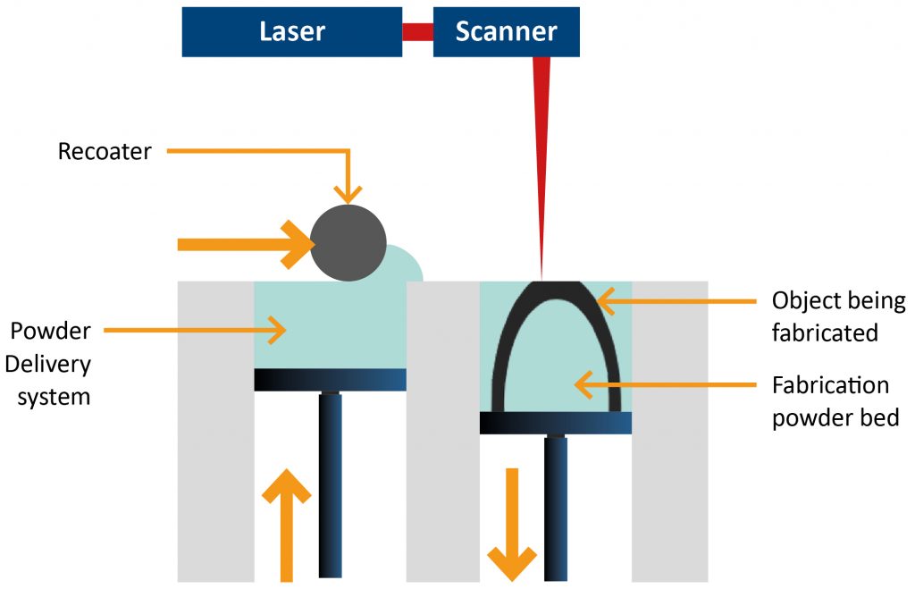
Powder Bed Fusion (PBF) is the most widely used metal Additive Manufacturing technology on the market today. In this process, a thin layer of metal powder is spread across the top of a build and exposed to a highly-focused laser or electron beam heat source to melt it in rapidly-solidifying layers corresponding to a 2D slice of the 3D design. This process is carried out repeatedly until the build is complete. (Fig. 1)
AM enables engineers to produce very complex shapes and typically results in a near net-shape part. This design freedom offers a wide range of creative opportunities for lightweighting, part consolidation and customisation. It is this capacity for weight and size reduction and customisation which has attracted the aerospace and biomedical communities to the technology as early adopters.
At Ansys, many of our customers are interested in metal Additive Manufacturing, but few have purchased machines and even fewer have more than several parts in actual production. As a result, the tremendous desire within the industry to take advantage of the opportunities afforded by Additive Manufacturing is not currently being realised in practice. There are more than a few reasons for this, with major factors being the cost of the machines, the staff required to run them, and the design and process changes required to take advantage of AM.
In terms of the Gartner hype cycle, the industry as a whole is past the point of ‘inflated expectations’. It has realised the reality and passed through the ‘trough of disillusionment’ stage, and is on the upward ‘slope of enlightenment’, moving slowly toward truly productive use of the AM process.
Challenges facing wide-scale adoption of AM
There are many other reasons adoption has been slow. The AM process involves very complex and chaotic physics which can be difficult to control, predict and measure. It also involves extreme scales, both in time (microseconds for laser heating, hours or days to build the part) and space (microns for the melt pool size, decimeters for the part size), while the variability in machines and processes can affect the final part quality.
Qualifying and certifying AM parts
The USA’s National Institute of Standards and Technology (NIST) defines qualification as “the collection of sufficient data to demonstrate that a material or process will function as expected.” Furthermore, the institute outlines three different paths that can be taken to qualification:
- Statistical-based qualification, rooted in extensive empirical testing
- Equivalence-based qualification, achieved through moderate testing to demonstrate that a new material or process is equivalent to a previously qualified material or process
- Model-based qualification, where a material or process’s performance is demonstrated in a computer model and verified with minimal testing.
Empirical testing (build and test) is expensive and time-consuming for the AM process. Using this method, it can take years to fully qualify a part and process, especially for the safety-critical parts used in many aerospace components. Using model-based qualification — simulation — is the quickest route to qualification and certification, and provides additional benefits compared to other methods. For example, understanding the impact of variability is one issue that can be cost-effectively solved using simulation. By creating a simulated or model process, the effects of machine parameters and material variation can easily be studied, along with build orientation and support design.
Of course, the design of the part itself also has an impact on the production quality. Quality is measured by two parameters: 1) the conformance of parts to the design geometry (distortion and the underlying residual stresses are endemic problems with metal AM), and 2) material properties of the as-built part.
Understanding and preventing distortion
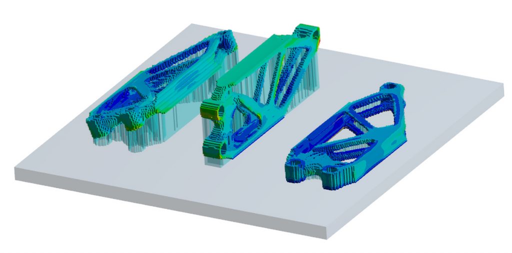
The layer-by-layer heating and cooling involved in PBF AM induce large thermal strains that cause plastic deformation in the part as it is built. Once removed from the build plate and its supports, the residual deformation can be quite large (Fig. 2), leading to unusable parts or parts requiring extensive machining operations to bring them into compliance. Large residual stresses and plastic strains are also present, requiring heat treatment to relieve the stress, which increases manufacturing cost and time.

While machine parameters such as build plate temperature and scan pattern play a role, the primary mechanism for controlling distortion is the orientation of the part and the support structures (Fig. 3).
Material properties
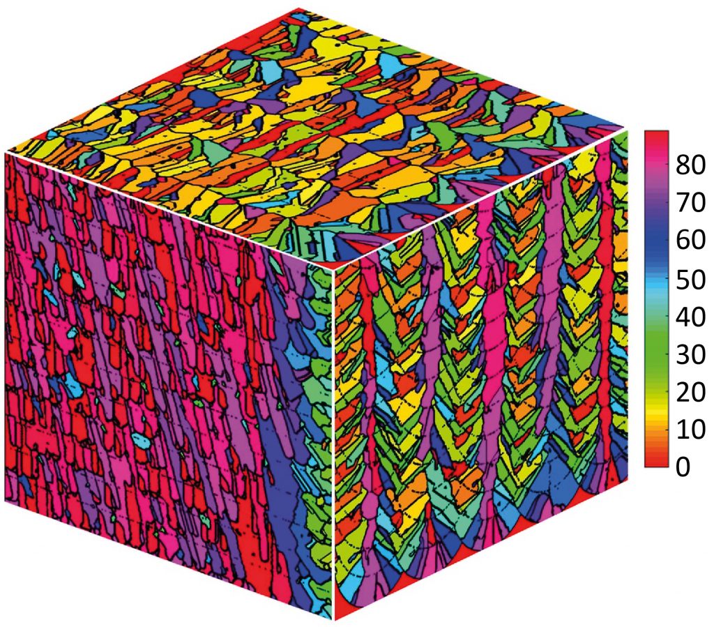
The PBF Additive Manufacturing process involves quickly heating a very localised area of powder (tens of microns in size) to melt it, followed by rapid solidification. This cooling rate is orders of magnitude faster than casting, causing unique and, in many cases, non-equilibrial microstructures to develop. Since the material is added layer-by-layer, the resulting microstructures are columnar in nature (Fig. 4) leading to a different stress-strain response in the build direction versus the transverse direction.
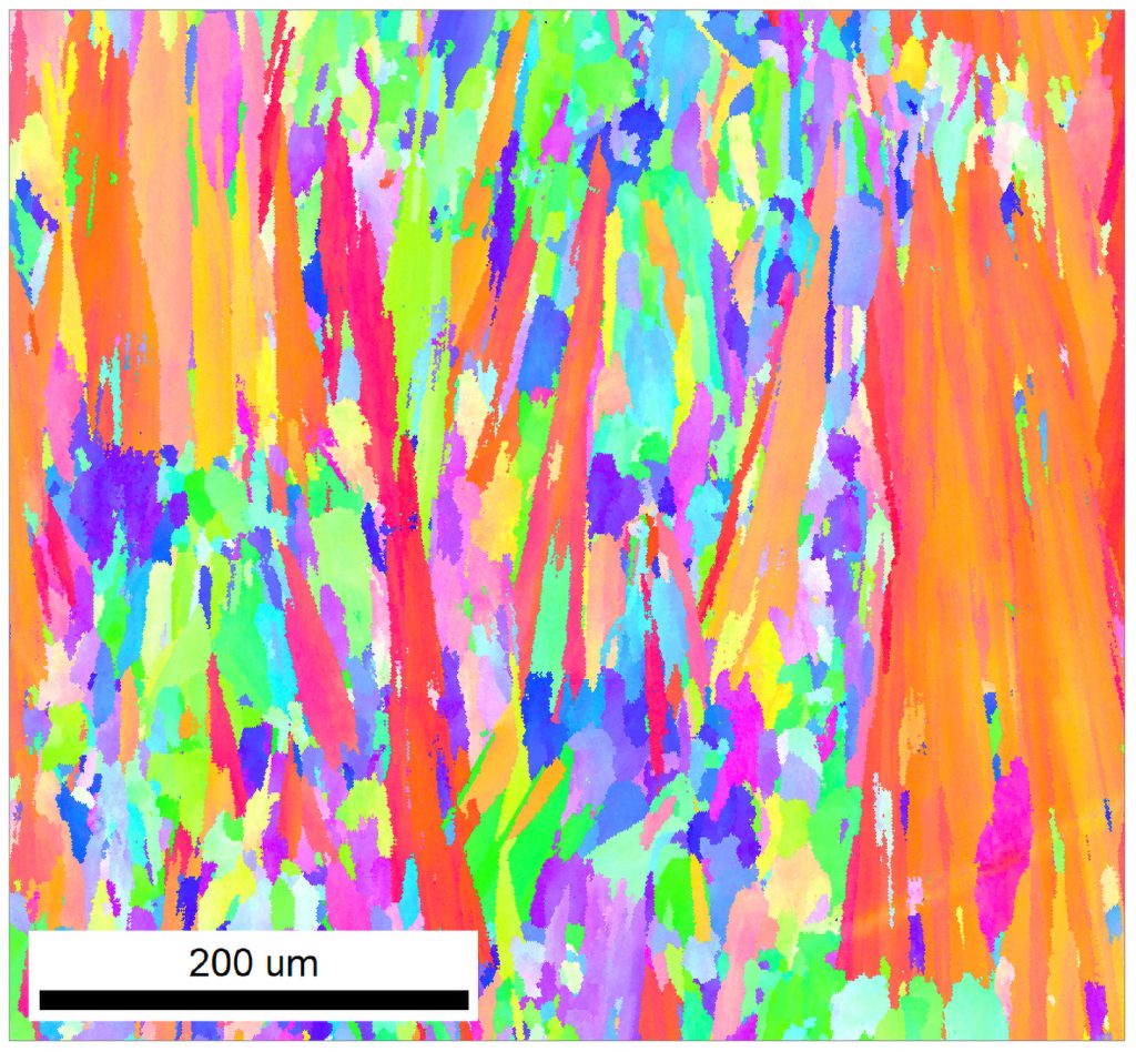
Scan patterns, part thickness variability, overhangs and the upward or downward sloping of a part face during the build can lead to variable microstructures, resulting in different engineering properties throughout the part. Heat treatment can alleviate this, but at the cost of an additional step in the manufacturing process. Porosity left behind during the process can also be a concern. Hot Isostatic Pressing (HIPing) is required for parts subject to any type of cyclic (fatigue) loadings.
In addition to the potential heat treating and HIPing operations mentioned above, manufacturers must also consider post-processing operations such as support removal, surface finishing and additional machining.
Simulation as an enabler
Given the issues outlined above, it is perhaps not surprising that companies have been slow to adopt and advance metal AM as a standard (i.e. qualified) manufacturing process alongside machining, casting, forging, etc.
Simulation of the Additive Manufacturing process has now evolved to the point where it can have a measurable impact on the design and production of quality parts. Design here means not only traditional product design (i.e. a product’s geometry) but also the design of the machine build parameters, part orientation, supports and post-processing steps.
This is not to claim we are at the point where simulation can completely replace trial and error builds, but it can certainly augment and significantly reduce the need for them. Additionally, simulation can be used to understand and quantify variability, providing valuable insight and direction that a single test build cannot provide. This allows companies to manage the risk of AM and achieve certification via model-based qualification. (Fig. 5).
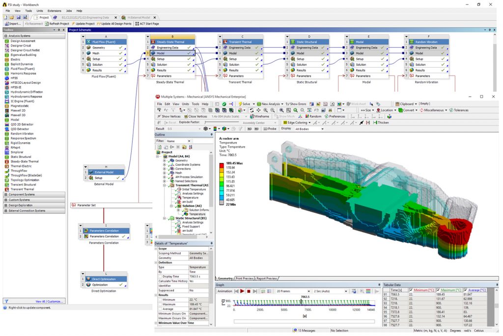
Ansys recognises that there are three roles involved in the path to quality: the product design team, the machine operator and the manufacturing specialist/materials engineer.
Product design
Simulation has long played a role in the product design cycle. Now, engineers are increasingly asked to design for the additive process. For effective Design for Additive Manufacturing (DfAM), they should ask:
- Is this design good for AM?
- Does it make use of its benefits (geometric complexity, part consolidation, unique cooling channels, etc.)?
- Will this part build correctly?
- Is distortion going to be a problem?
- How should I design the supports?
Many companies have found that upfront engineering is required for good support design — meaning adequate strength and sufficient support locations — rather than depending on geometry-based processors downstream to the design process.
Ansys Workbench Additive enables engineers to answer these questions. In addition to the usual simulation of how a part works in the field, designers can also simulate the build process to look at distortions and residual stresses and how orientation and support design will affect them, including their optimisation. Workbench Additive also includes topology optimisation, a generative design tool which lays out part geometry based on the loads encountered, leading to shapes that can be produced easily by the AM process.
Machine operator
The operator of an AM machine receives a design (typically in STL format) from the design group, and their job is to successfully build it. Success means one build job, with minimal distortion (conforming to the desired geometry), minimal residual stress, minimal build time and minimal supports (since these take time and material to produce).
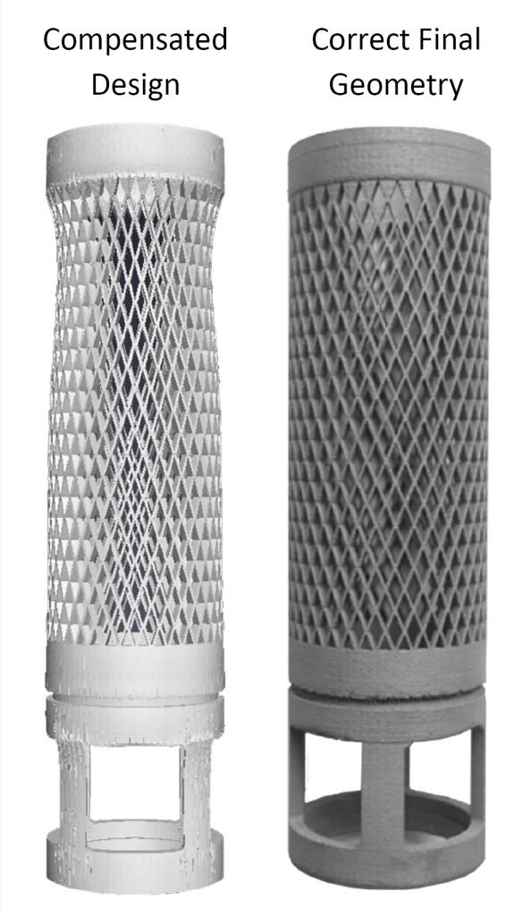
Ansys Additive Print enables the operator to investigate the best options for a part build. It uses simulation ‘under the hood’, but the interface is geared toward a technician rather than an engineer. Additive Print allows the operator to investigate orientations and optimise support sizing to achieve a successful build first time. Additionally, the operator can have the software modify the STL file that is input to the AM machine so that when the built part does distort, it distorts to its as-desired shape (Fig. 6).
Manufacturing specialist
The manufacturing specialist provides the ‘recipe’ — the machine parameters, including laser power and speed, hatch spacing, scan patterns, etc. — to the operator in order to meet the desired part quality. They also supply design guidelines to the product design group. Historically, this knowledge is built up through experience of many test builds, starting from single beads, to cubes and pads, to canonical geometries, to prototype parts. Testing this way offers good insight but is insufficient for qualification without prior months or even years of data acquisition.
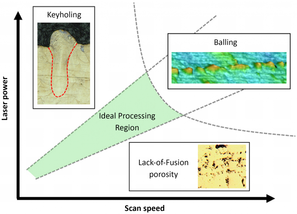
Ansys Additive Science provides insight into machine parameters and materials. It allows the manufacturing specialist and the materials scientist to answer such questions as how machine parameters like power and speed affect melt pool size and porosity. The laser power-speed process map (Fig. 7) can be found experimentally for a given machine and material. However, simulation provided by Additive Science lets the manufacturing specialist explore these boundaries to understand how variability in, say, laser power degradation over time, affects the built part.
Additive Science can also provide detailed microstructure output to explore material variability due to scan strategies and part location (Fig. 8).
An important output from full-part simulation is sensor readings, which allow correlation with actual sensor outputs. Having a simulation model of the expected sensor readings — a ‘digital twin’ of the actual build process — allows understanding and correction of builds during the process.
Future trends
Because AM is a rapidly evolving field, the future is difficult to predict with certainty, but there are some overarching trends. New machine manufacturers are appearing, along with new and significant upgrades to existing machines. These machines are becoming more reliable. As one customer stated, “they are becoming industrial machines and not prototypes”. Multiple lasers and enhanced scan patterns are leading to more even heating on a layer, reducing distortion and providing more even microstructure.
Novel alloy development will accelerate, taking advantage of the fact that, in AM, the material is built as well as the part. Mixing powder chemistries and taking advantage of non-equilibrial cooling rates will lead to the development of materials unthought of today.
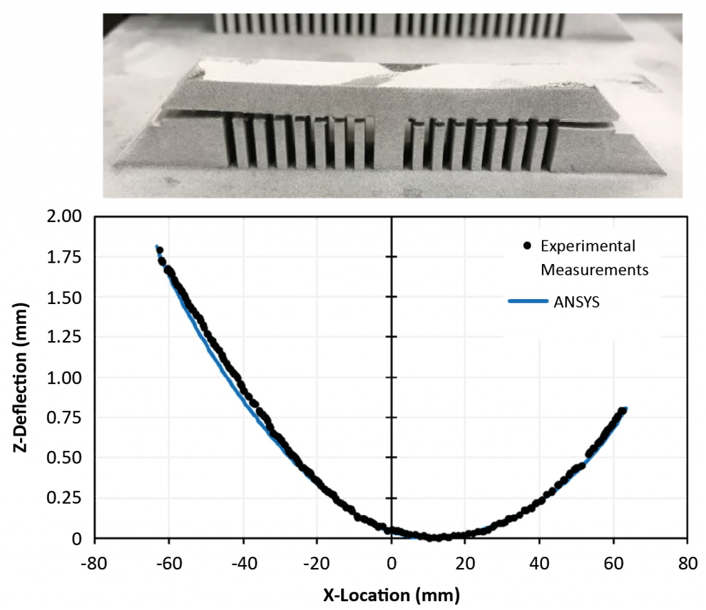
Software — from design to simulation to build preparation to machine interfacing — is maturing and consolidating, providing a more even user experience. Simulation software in particular is maturing, as researchers advance the state-of-the-art and users gain experience. Ansys provides a Validation Manual with its software (Fig. 9) which not only gives users confidence in their AM simulation, but also insight into the usage and best practices of simulation. More automation and optimisation, such as orientation, support design and sizing, and even setting of machine parameters, will evolve in simulation software, leading to a ‘push-button’, right-first-time Additive Manufacturing experience.
Final words
The last few years have been quite a ride for metal Additive Manufacturing. While the promises of metal AM are great, the reality of investment cost and qualification continues to limit its growth. Simulation, though, can smooth and accelerate the road to adoption and acceptance.
Author
Dave Conover
Chief Technologist, Mechanical Products
Ansys, Inc.
Southpointe
2600 ANSYS Drive
Canonsburg, PA 15317
USA
Email: [email protected]
www.ansys.com


