


Design for Additive Manufacturing presents opportunities for software developments
Designing a component for AM whilst taking advantage of all the opportunities that the technology presents can result in many variables. Even a group of experienced Design for Additive Manufacturing (DfAM) experts will end up with significantly different build strategies for an identical part. In the following article, Olaf Diegel and Terry Wohlers consider how software innovations could further streamline the AM process, from part positioning and stress management to surface finish considerations and quality control. [First published in Metal AM Vol. 4 No. 2, Summer 2018 | 10 minute read | View on Issuu | Download PDF]

After a part has been designed for Additive Manufacturing, it must be prepared for production on an AM system. This is usually done using software provided by the system manufacturer or with generic AM file preparation software. The steps include setting up the part orientation on the build platform and generating the support structures, also referred to as anchors, for the part, as well as selecting build parameters and nesting multiple parts on the platform to make the build as efficient as possible. If you do not, the cost per part can become unaffordably high.
With any AM process, the decisions made during the file preparation process can have a vast impact on the surface quality, part cost and mechanical properties of the part. Also, they can affect the amount of manual post-processing that needs to be undertaken after the part has been manufactured. Due to the very high thermal stresses acting on a metal part during the build process, choosing the best build orientation, support material strategy or process parameters can prevent machine crashes and disastrous results.

Today, the software used to prepare a metal AM component for production relies on the knowledge and experience of the operator to set up a part in the best possible way. This means achieving the best surface finish, best mechanical properties, shortest print time and easiest support removal method. The removal of support material involves cutting and grinding away metal that is welded to the part. If three different machine operators set up the same part for a build, the results are three different part qualities because they will each likely use a different approach.
This state of affairs is one of the factors which adds a level of difficulty to metal AM and impacts its adoption by industry. Even so, it represents a great area of opportunity for software developers to create more intelligent software which streamlines and automates as much of the AM file preparation process as possible. Although the examples presented here refer to metal Powder Bed Fusion (PBF), many of the principles apply equally to other AM processes.
Automatic part positioning
It should be possible to analyse a part and, based on a number of factors, automatically orient it in a way that makes production as reliable and low-cost as possible. The decision on how to best position a part on a build plate is critical and is driven by the following factors:
Anisotropic direction
An anisotropic part is one with mechanical properties of varying values in different directions. This must be taken into account when positioning a part in an orientation that results in the highest possible strength for the features that require it most. This is usually the horizontal position, or as close to horizontal as possible. The orientation is often a compromise, because a part may have features in multiple directions.
Feature quality
Holes that are printed horizontally are usually not round, but slightly elliptical, and suffer from a ‘stair step’ effect caused by the layer-upon-layer build process. Also, because of the stair step effect, gently curving surfaces can vary in quality, especially when a surface is nearly horizontal. The quality of other features, such as text, can differ substantially depending on the build orientation. Such decisions could serve as good input for software that automatically suggests the best orientation of a part.

Surface quality
With AM, down-facing surfaces usually suffer from poor quality, compared to up-facing surfaces. Surfaces that are the most critical can play a role in making decisions about part orientation. This decision, however, is not always obvious. In some cases, the down-facing surfaces will need to be machined, so it would make sense to position the most critical surfaces downward, thus guaranteeing the best surface finish with machining.
Residual stress
Residual stress can occur whenever metal is cooling. Large masses of metal in a part, or sudden changes in the cross-sectional area of a part, can especially affect part quality. This is because the thicker parts cool down slower than thinner parts, and can distort the part or create a weakness within it. Residual stress is also one of the main reasons why parts are usually heat-treated after printing. Proper heat treatment will relieve the built-up stresses.
Suppose all design precautions have been taken into account to minimise residual stress, such as minimising large masses of materials. In the case of laser-based PBF, the main parameter that a user can control to reduce residual stress is the laser scan strategy. In a part with large surface areas, the laser hatching can have a profound effect on residual stress. A ‘chessboard’ pattern, for example, creates less residual stress than a large ‘meander’ pattern, although the chessboard pattern builds more slowly. Rotating the scan directions for alternating layers, usually by 67°, can also help to prevent residual stress in a single direction.
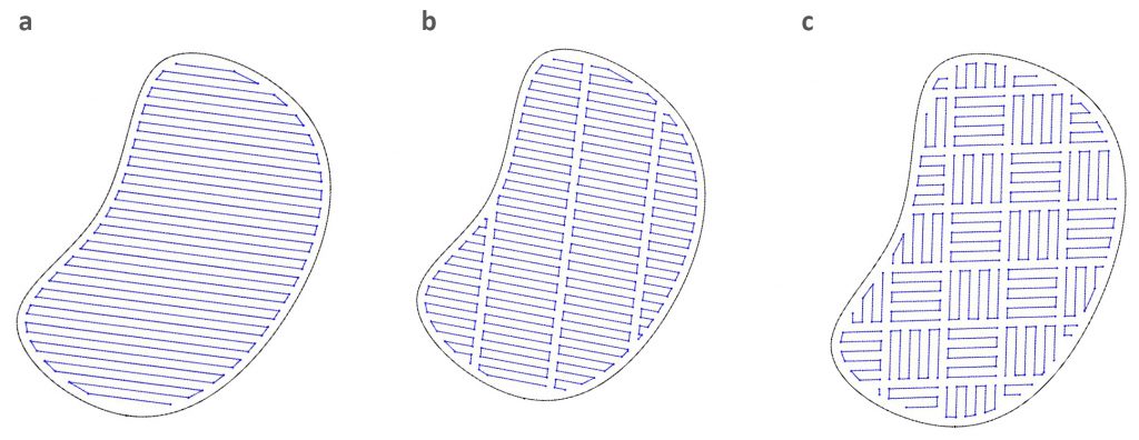
Fig. 2a shows a meander hatch pattern, which offers a high build rate but high residual stress. This is suitable for small and thin parts. Fig. 2b is an example of a stripe hatch pattern. This offers a medium build rate and medium residual stress and is suitable for medium-sized parts. Fig. 2c shows a chessboard hatch pattern, which builds more slowly but offers the lowest residual stress of the three. It is most suitable for large parts.
Maximum build speed is always desirable, and improved software could help. Based on analysis and predictive results of the residual stress, the print preparation software would dynamically change the laser scan hatch pattern to best minimise the residual stress for each feature of a part.

Large horizontal areas
When building large horizontal surfaces on most AM systems, the build material tends to curl upward and detach from the support material. This can result in the formation of cracks. Rotating a part by 10–45° will reduce the size of large cross sections, although it can greatly increase print times. Changing the laser scan strategy for the hatch pattern can minimise the problem, presenting the opportunity for part preparation software to automate the process.
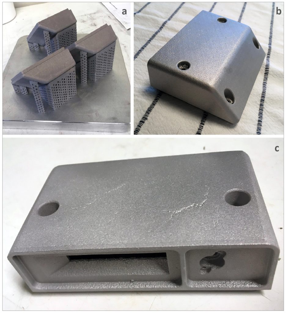
Fig. 3 shows an electronics enclosure measuring 99 x 80 x 33 mm. The surface is good when printed at a 45° angle. The time to build three parts at this orientation is 54 hours. Fig. 3c shows the enclosure printed horizontally. Three copies of the part took only 22 hours to produce, but cracks developed on the bottom surface.
Support material requirements
Any surfaces below a certain angle, often 45°, require support material that needs to be removed. This support material also serves as a heat sink to help prevent distortion of the part and its features. The supports also serve to resist the mechanical force of the powder spreading mechanism, which might otherwise push and move the part. For this reason, it is critical that the part be well-anchored to the build platform, with the support material helping to prevent thin vertical sections of the part from being bent or knocked over.

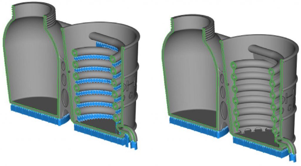
Additional software improvements related to the generation of support material are possible. One interesting DfAM technique is to replace support material with a wall that becomes a permanent feature of the part. Consider the distillery design in Fig. 4. The blue sections represent support material which allows the transfer of heat down to the build plate. One option is to replace the support material between the coils with permanent walls, which serve the same function but do not need to be removed after production. This could be automated through software by giving the user the option to choose between supports or permanent walls.
Quality assurance
Many system manufacturers now offer in-situ process monitoring options that produce a digital image of each layer of the build. Currently, they offer little intelligence, leaving it to the user to review the images manually to identify why a defect has occurred. This is another opportunity for software automation. Image processing systems have been available for many years and are currently being used in a number of industries to automatically identify flaws in products. One can imagine future AM systems analysing and drawing a conclusion from each image as it is taken. If an error occurs, such as unintended porosity, the software would make the decision to reprocess that area and/or pinpoint the problem and alert the person responsible for the machine.
Future software developments
Improved software could also help in other areas of metal AM. For example, it is possible to consolidate two or several parts into one, digitally, and then build a much more complex part. Airbus, GE and many other companies have done this successfully and serve as inspiration for a growing number of organisations that are adopting metal AM. However, part consolidation requires experience and skill. New software tools could help the designer by suggesting which parts could be combined into one, making the process easier and more streamlined.
Another area is the use of topology optimisation and lattice, mesh and cellular structures to reduce material and weight while producing strong parts. Many software tools that offer these capabilities have been commercialised, but most are stand-alone and not seamlessly integrated into the design and AM work flow. The AM industry has the opportunity to use generative design and cloud computing to further streamline the product development and manufacturing process and intelligently suggest new designs based on a number of inputs and parameters. The integration of AM design rules and guidelines would also help designers reduce the costly and time-consuming process of trial and error to a minimum.
These examples of the automation of important process steps through software only scratch the surface of the challenges and opportunities of manufacturing good metal AM parts. However, they identify some of the areas in which intelligent software could make metal AM easier to use as a technology, and thus help to increase its industrial adoption. Software tools for part consolidation and other methods of design could be fully integrated into the AM work flow and greatly assist designers. These needs are significant and greatly impact the economics of metal AM, so request and watch for these capabilities in the future.
Authors
Olaf Diegel and Terry Wohlers
Wohlers Associates, Inc.
Fort Collins
Colorado 80525
USA
LAST MONTH’S MOST-READ ARTICLES


