


How process parameters drive successful metal AM part production
A number of factors drive the selection of process parameters in Laser Powder Bed Fusion (LPBF). In this invaluable resource Marc Saunders, Renishaw plc’s Director of Global Solutions Centres, details how these parameters define the ‘operating window’ in which AM users must work, and offers advice on identifying the ideal process parameters for metal AM parts. The sensitivity of the process to changes in part geometry is also considered, along with how this may drive part developers towards application-specific parameter choices. [First published in Metal AM Vol. 4 No. 2, Summer 2018]
To ensure the successful production of metal components by Laser Powder Bed Fusion, it is important to carefully consider the processing parameters used to melt and solidify the metal powder on the powder bed to the desired shape. Because the thermal response of an alloy affects both its integrity and strength, the correct parameters must be selected to suit the material in question and the requirements of the as-built component. This becomes especially important in the context of series production, where the repeatability of the AM build process is key to avoiding quality issues further down the line.
In the LPBF process, a powerful ytterbium fibre laser beam is focused onto a small spot that contains sufficient energy intensity to fully melt a thin layer of metal powder. To direct the laser energy, a pair of articulating galvanometer mirrors are combined to move the spot across the powder bed. The result is a track of solid metal securely welded to its neighbour and the layer below. A shielding gas flow then passes across the build plate to safely remove process emissions while protecting the heated metal from oxidation.

Each weld track is somewhat wider than the laser spot (by as much as 2–3 times the spot diameter), as the heat from the laser is conducted into the surrounding powder particles, incorporating them into the moving melt pool. Multiple melt tracks are joined together and overlapped to create a solid layer corresponding to a slice through the component. The melt track must also be sufficiently deep to partially re-melt the layer below to form a fully-dense solid structure. In this way, the component is built up slice by slice.
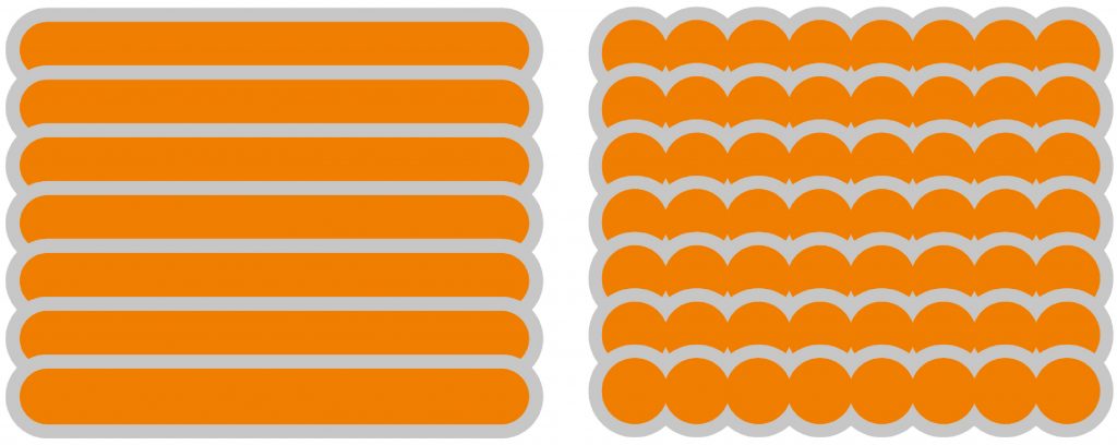
Two main techniques are used to melt powder – continuous and modulated scanning (Fig. 2). In continuous mode, as the name suggests, laser energy is delivered continuously to melt the powder by guiding the laser beam to and fro across the surface of the powder bed to solidify the metal. The scan lines overlap, so that each successive pass of the laser partially re-melts the previous scan line, creating a solid mass of welded material.
In modulated mode, the lasers operate in a slightly different way. Here the laser is turned on and off, creating a series of exposures, with a short (10–20 microsecond) pause between them. Each exposure partially overlaps with the previous one. These can be formed into similar scan lines that move efficiently across the powder bed to solidify the bulk of the component.
Process parameter basics
- The way in which laser energy is transferred into the powder bed is governed by process parameters. These define how much energy is applied and how fast. The critical parameters are:
- Laser power: the total energy emitted by the laser per unit time
- Spot size: the diameter of the focused laser beam – this may be fixed or programmable depending on the focusing system on the machine
- Scanning velocity: the speed at which the spot is moved across the powder bed along a scan vector – this is defined by point distance and exposure time on a modulated laser system
- Hatch distance: the spacing between neighbouring scan vectors, which is designed to allow a certain degree of re-melting of the previous weld track to ensure full coverage of the region to be melted
- Layer thickness: the depth of each new powder layer to be melted.
- Each of these parameters can be adjusted independently, making parameter selection a multi-variable problem.

Finding the operating window
The first consideration when choosing the parameter is to achieve a consistent, fully-dense component. Part density is a key indicator of melting quality – if the part is porous, it is unlikely to exhibit the strength, ductility and fatigue / creep performance that we need. But with so many parameters to play with, how do we choose the right combination?
Simplifying things helps. For any given build, the powder chemistry and particle size distribution are fixed. We are also likely to fix the layer thickness based on the resolution and surface finish that we need for our component. If we also fix the laser spot size (which cannot be varied mid-build on many machines) then we are left with power, speed and hatch distance.
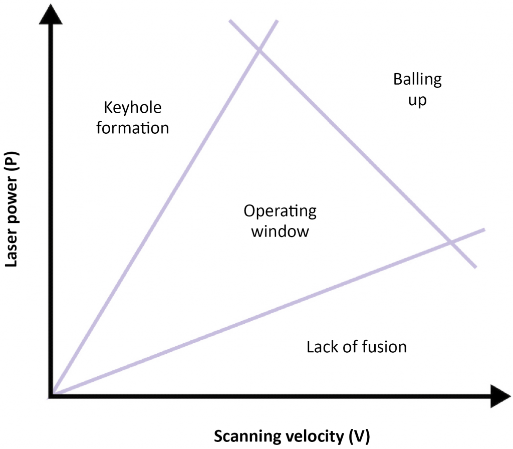
The explanation below is adapted from work by Robert M Suter and colleagues at the Stewardship Science Academic Programs (SSAP) Symposium in Chicago, April 2007 [1]. A helpful way to think about this is to plot our parameter choices in P-V space, plotting laser power (P) against scanning velocity (V). Our choice of parameters will affect the process outcome, as shown in Fig. 3. If we scan too fast with too little power, then we will see regions of the part which do not fully melt, leading to ‘lack of fusion’ porosity. By contrast, if we apply too much power for the chosen speed, then we may overheat the melt pool, causing deeper energy penetration and leading to an effect known as ‘keyhole formation.’
Between these two extremes lies an operating window where we will achieve good part density. Here, the energy from our laser is sufficient to fully melt the powder and underlying metal without penetrating too deeply. Fig. 3 suggests that we can increase both power and speed together to build faster, and to an extent this is true. However, there is a limit to how hard and fast we can go, beyond which the weld pool behaviour becomes unstable and we get a beading effect known as ‘balling up.’ We also tend to see an increase in spatter formation at higher laser power.
Processing in the operating window
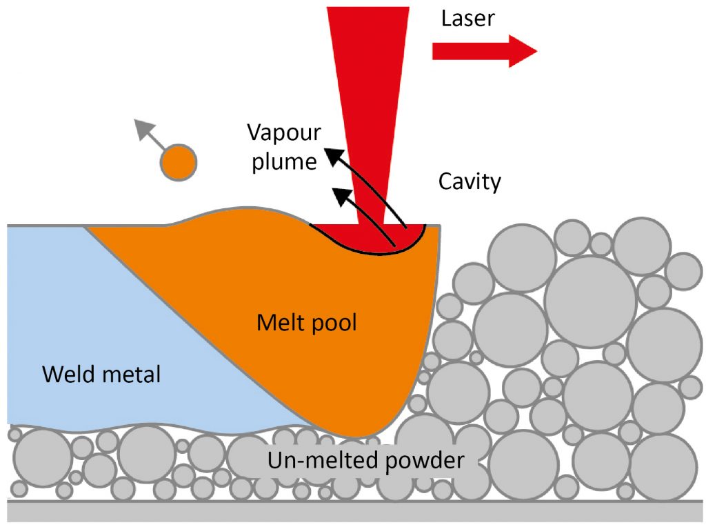
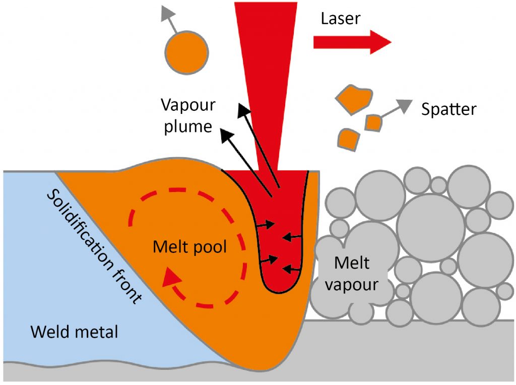
The central operating window on the P-V diagram in Fig. 3 is where the right combination of speed and power generates a stable melt pool of the optimum size. It is where the laser energy is being efficiently absorbed by the powder, creating a melt pool of sufficient depth to fuse strongly with the layer below whilst avoiding excessive re-melting.

In this processing zone, the laser recoil pressure creates a shallow cavity. The laser heats the front face of this cavity as it moves, creating a metal vapour plume that is ejected normal to the surface – i.e. upwards and backwards. The shallow cavity does not allow for internal reflections, so no additional melting occurs. Heat energy is conducted into the melt pool, which experiences a degree of turbulent flow due to the high temperature gradients within it and the surface tension. This flow will result in some matter being ejected in the form of weld spatter.
The moving vapour plume creates an environment around the melt pool that is analogous to a weather system. It can entrain powder from next to the weld track, drawing it towards the laser beam through the Bernoulli effect and then ejecting it outwards. Some of this material will be heated as it passes through the laser, while other material is blown around by the induced gas flow in the form of ‘winds’ adjacent to the laser beam.
Lack of fusion
If we use less power for a given speed, then the melt pool will be smaller. This means that it is likely to experience less turbulence and generate less spatter as it solidifies more rapidly. The vapour plume will also be less vigorous and so entrainment of neighbouring powder will also be reduced.
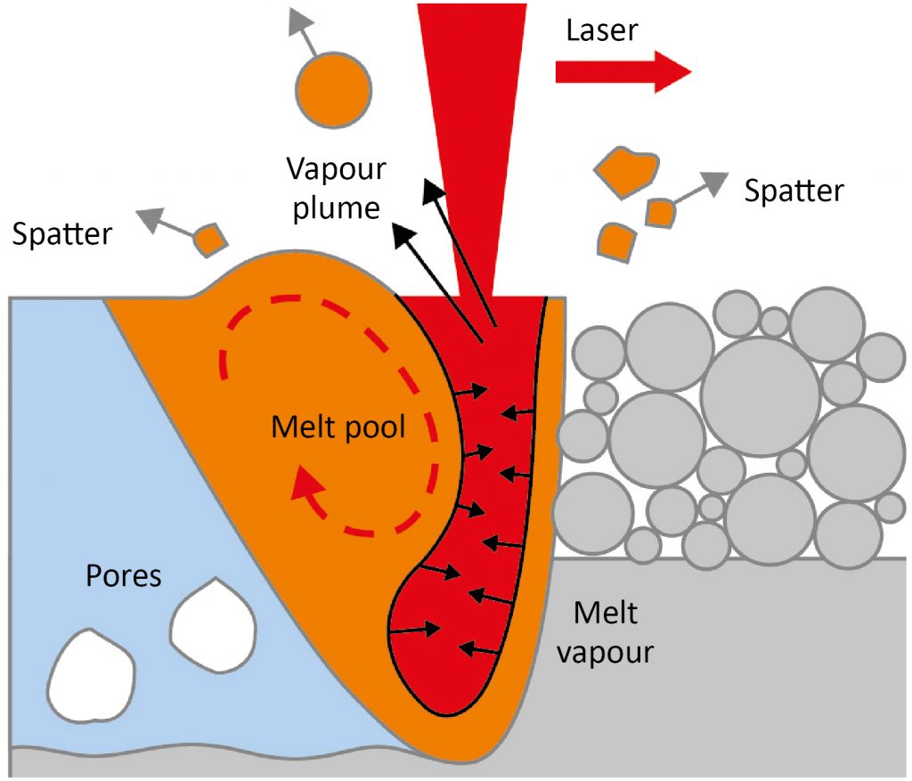
The bad news is that now the lower laser energy may not penetrate deeply enough to fully melt the powder layer and the top surface of the solid metal below. This leaves unmelted powder beneath the melt pool, resulting in excessive porosity and risk of delamination as illustrated in Fig. 5.
Keyhole formation
When too much power is used for a given speed, we see excess penetration of the laser into the metal under the layer of powder, forming a keyhole (Fig. 6). This deep melt cavity in the surface sees metal vapour being ejected more vertically than before. Internal reflections of the laser energy within the cavity trap more heat deeper in the material, leading to a deeper, longer-lasting melt pool. This increase in energy input will increase melt pool turbulence and spatter formation, whilst a stronger ‘weather system’ will lead to more powder entrainment.
Where the keyhole becomes unstable (affected by power, scan velocity and melt pool dynamics), the melt pool can collapse in on the cavity to form a pore of inert gas at the base. Such pores may not close up as the melt pool solidifies, generating sub-surface porosity in the welded metal. A greater degree of re-melting of the layers below will also occur, affecting the microstructure of the solidified material (Fig. 7).
Experimental evidence from the National Institute of Standards and Technology (NIST) illustrates the impact of parameter choices on melt pool size (Fig. 8) [2]. Measuring an Inconel melt pool from above using an infrared camera, NIST observed that the melt pool length is roughly constant for different scanning speeds at the same laser power. However, the melt pool width, and hence area, increases as the speed reduces. In this case, at 200 W laser power, the length of the melt pool is approx. 0.6 mm at speeds varying from 200 mm/sec to 800 mm/sec. The wider (and thus deeper) melt pool created at slower scan speeds contains more thermal energy and so takes longer to solidify – up to 3 ms in the most extreme case.
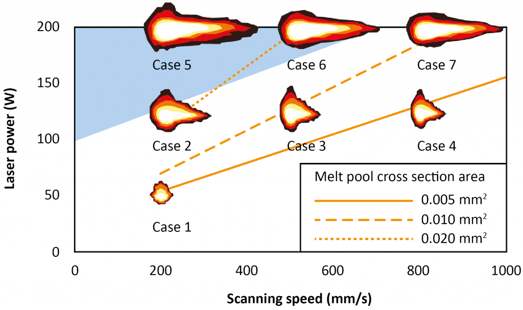
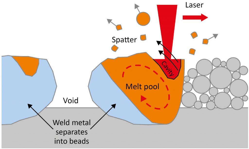
At higher speeds, the melt pool can become unstable. High surface tension gradients can lead to the formation of voids behind the laser beam that expand as the laser moves on, causing the melt pool to break apart into separate islands that solidify as beads (Fig. 9).
Solidification and microstructure
So far, we have considered the melting aspects of the LPBF process and their effect on part density. It is, however, the solidification process that is most critical to establishing the performance characteristics of the metal component. Solidification defines microstructure, which in turn drives material properties.
Many alloys are complex and can exist in multiple phases at different temperatures and compositions, and so solidification does not happen all at once. Nor does it happen uniformly within a typical weld track. Cooling is most rapid where the heat can escape and most of the heat is conducted out of the melt pool and into the surrounding solid metal. Relatively little heat is lost into the neighbouring unmelted powder, or via radiation up into the chamber.

As the molten metal cools, the outer regions of the melt pool fall below the liquidus temperature and one or more phases of the alloy will start to solidify. Cellular-dendritic crystals form at the outer edge of the melt pool, growing in towards the centre. The remaining liquid phases are trapped between these primary dendrites, only solidifying once their lower melting points are reached. Opposing cellular-dendritic growth fronts form the individual grain boundaries where the remaining liquid phase can also accumulate.
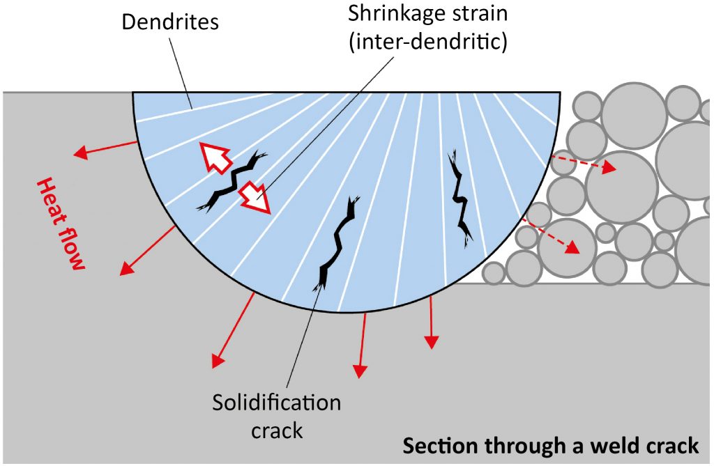
The cooling process places strains on these cellular and grain boundary regions, which can result in unwelcome porosity through a process known as ‘hot tearing’ or solidification cracking in some materials (Fig. 10). This is worst where there is a large difference between the temperatures at which the different phases solidify.
As we can see, the size, duration and cooling rate of the melt pool is important, as it governs the thermal response of the material. A longer-lasting melt pool that cools more slowly will produce a coarser microstructure, with larger grains and thicker dendrites. By contrast, smaller melt pools will cool more rapidly, creating a finer microstructure.
A deeper melt pool will also cause more re-melting of the previously-solidified metal, as well as affecting its microstructure. Higher laser power correlates with the formation of longer columnar vertical grains, each spanning multiple layers. Since a deeper melt pool has a larger contact area with the solid metal below, more heat is conducted downwards, increasing the vertical alignment of grains. This can result in a greater difference between mechanical properties in directions perpendicular to and parallel with the build direction (Fig. 11).
The ideal operating window
So, we are looking for a combination of speed and power that creates a melt pool of the optimum depth, width and duration. This means putting the optimal amount of energy into our part. When we get this right, we achieve a combination of low porosity with a microstructure that yields our desired material properties and achieves an acceptable level of productivity.
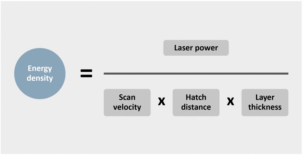
One way to think about this is in terms of energy density; the amount of energy that we apply to the material per unit volume. For a constant energy density, laser power and scanning velocity are inversely related to one another, so, in P-V space, energy density contours radiate from the origin, with the density being related to the gradient of the contour.
For our chosen material and layer thickness, there will be an optimum energy density at which it will process most efficiently and deliver the microstructure that we are looking for. When choosing our process parameters, we want to be as far along this contour as we can reach with the laser and focusing optics available on our AM machine, without venturing too far towards the ‘balling up’ region. This will give us the best material properties, combined with the best productivity.
Hatch distance
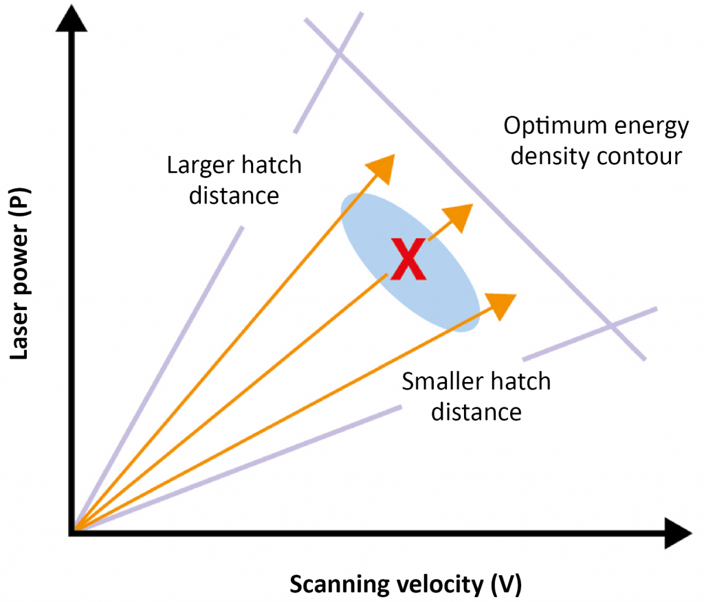
The analysis shown above is missing one crucial factor: hatch distance. Our graph assumes that the hatch distance is fixed, so that energy density is governed only by laser power and scan velocity. Of course, hatch distance can be varied independently of power and speed and it also affects the energy density. It is therefore possible to maintain the same energy density along a range of P-V contours by varying the hatch distance. We can put the same total amount of energy into the layer in many different ways (Fig. 13).
All three contours shown by the orange arrows in Fig. 14 have the same energy density. For instance, if we adopt a higher power-to-velocity ratio (i.e. we choose a steeper contour that is closer to the keyhole formation zone) we can keep the energy density constant by increasing the hatch spacing. This makes sense – if we create a wider, deeper melt pool with a more penetrative laser beam, then we can afford to space them further apart whilst still fusing them to one another.
However, by doing this we will see a drop-off in material properties for the reasons outlined above. By venturing close to the keyhole formation zone, we are also reducing the safety factor in our process, which may limit the applicability of these parameters to certain geometries. It is important to pick a hatch distance that keeps us on a central P-V contour that is well away from both the lack of fusion and keyhole formation zones.
Whilst parameters in the blue zone in Fig. 14 should provide acceptable results, the ideal operating point is still that defined by ‘X’. Since most of the energy from the laser beam is absorbed within the laser spot in the centre of the melt track, a hatch distance that is similar to the spot size (or approximately half the width of the melt track) is generally most effective.
Layer thickness
In the above discussion, layer thickness was fixed. What if we vary this too? If we are not too concerned with surface finish, can we increase the layer thickness to increase build rates? The answer is yes – up to a point. Clearly, thicker layers require deeper penetration of the laser energy to ensure complete fusion to the metal below. To achieve the optimum volumetric energy input to fully melt the material, as we increase the layer thickness, we must also increase the energy input per layer. Our energy density contour therefore becomes steeper.
Increasing layer thickness pushes the ‘lack of fusion’ region on Fig. 15, narrowing the gap between it and the keyhole formation zone. The keyhole formation zone itself may not vary much with layer thickness, since this behaviour is governed by the intensity and speed of the laser spot and how this interacts with the material.
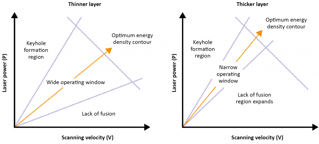
The operating window is therefore closing and eventually we reach a layer thickness where we cannot penetrate deep enough whilst maintaining a stable melt pool and sufficient fusion to the metal below.
The practical layer thickness that gives us a reasonable operating window varies with material, but generally falls in the range of 30 to 90 microns for laser spots of 70 to 100 microns in diameter for laser powers up to 500 W. Thicker layers can be accommodated by increasing the spot size to reduce the spot intensity at higher laser powers. However, this change is accompanied by a loss of fidelity, an increase in melt pool size and spatter formation, and may also affect the microstructure and material properties.
Why do we need a safety factor?
The reason that we want to process in the middle of a wide operating window is that we will not always face constant thermal conditions in all regions of the build. As each new layer is added, heat is conducted down into the previously built layers below. How well this heat is dispersed will depend on the local geometry of the component and the material properties.
Where there is a good thermal connection to the substrate below, heat will dissipate effectively (Figs. 16a, 16b). By contrast, if the part geometry involves thinner walls, or if there is a bulky region immediately above a much thinner section, then heat will not be able to flow down so easily, resulting in more heat being retained near the top of the part. This effect is most marked in materials with a relatively low thermal conductivity, such as Ti6Al4V.
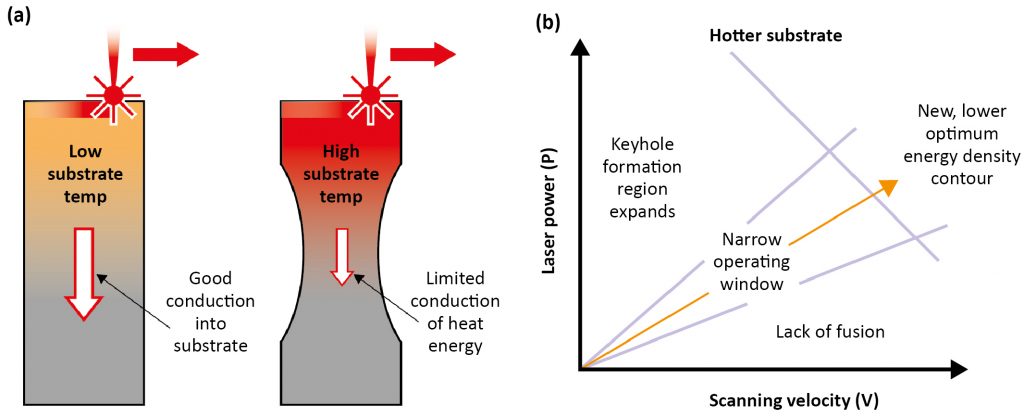
In these conditions, the substrate and the powder are preheated and thus require less energy input to create the same melting effect. The impact of this preheating on the melting process is to expand the keyhole formation region, reducing the power at which keyhole porosity will occur. The new optimum energy density contour is lower than before, and the operating window is narrower.
One possible remedy is to use simulation to identify the regions of the part that are most likely to overheat, and to reduce the laser energy input in these regions to offset this pre-heating effect.
Combining this point with the previous one on layer thickness leads to the conclusion that building thin-walled parts in thicker layers will be particularly challenging.
Nominal and specific parameter sets
So far, we have concentrated on finding the ideal bulk processing parameters for a material, enabling us to produce good metal as quickly as we can. But a working parameter set requires more than just one setting, as we encounter different melting and cooling conditions in different regions of our component. To deliver functional parts, we need to complement our bulk parameters with specialised settings for the various geometries that we are producing.
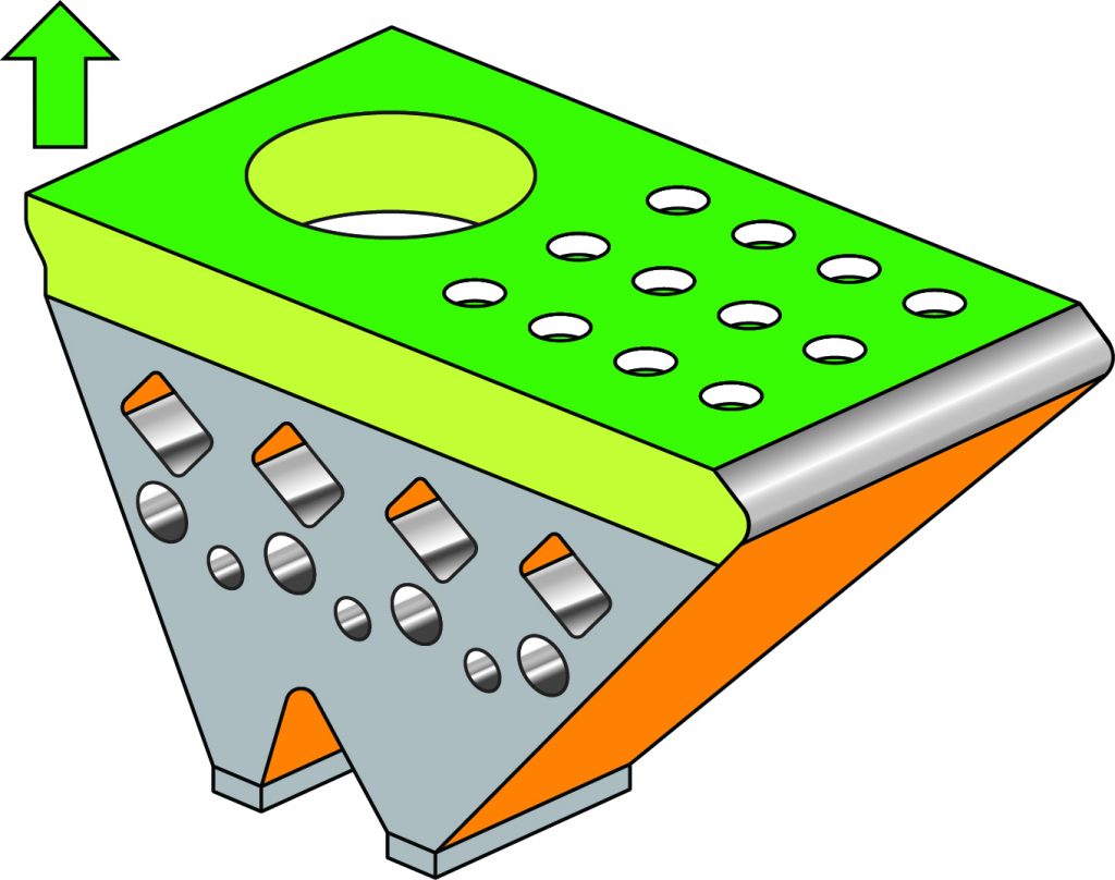
Every component will comprise both bulk regions and surfaces orientated in various directions. In the bulk regions we want high density, rapid build and good material properties. Our priorities for borders will be different – surface finish may be our biggest concern, or it may be suppression of surface defects that could lead to damage during post-processing. Down-skin surfaces typically cool more slowly, as they lack a solid substrate below, and here we are trying to avoid distortion and dross (Fig. 17).
We typically deploy quite different parameters in these regions and so even nominal parameter sets include a range of settings and scan strategies for different regions of the part. To achieve the optimum quality in all regions of the part, it may be necessary to develop more application-specific parameters.
Summary
Process parameter selection is critical to the success of our AM build, as it governs how the material will melt and solidify to form our component. Since each alloy powder absorbs laser energy, transmits heat, flows and solidifies in different ways, our choices must be tailored to the characteristics of the alloy that we are melting.
We must work within the capabilities of our AM machine to find an operating point in the middle of a wide operating window. This provides a safety margin to accommodate a range of local melting conditions. Even so, some part geometries may demand modified parameters to accommodate variations in retained heat. Borders and down-skin regions will also require different processing parameters and scanning strategies to deliver the required surface quality.
References
[1] Robert M Suter, He Liu and A D (Tony) Rollett, Towards optimal processing of additive manufactured metals for high strain rate properties’, SSAP Chicago, April 12-13, 2017
[2] J.C. Heigel, B.M. Lane, Measurement of the melt pool length during single scan tracks in a commercial laser powder bed fusion process, ASME 2017 12th International Manufacturing Science and Engineering Conference, June 4-8, 2017, Los Angeles, USA (MSEC2017-2942)
Contact
Marc Saunders
Renishaw Plc
Stone Business Park
Brooms Road
Stone, Staffordshire
ST15 0SH, UK
Tel:+ 44 1785 285 000
[email protected]
For further information, a hub to educate and inform AM users and the wider engineering community using videos, case studies, feature articles and opinion pieces has been created by Renishaw.

LAST MONTH’S MOST-READ ARTICLES


