

Eplus3D and Delta Racing develop AM wheel carrier for Formula Student race series
Eplus3D, Hangzhou, China, has showcased its Additive Manufacturing technology when the company collaborated with the Delta Racing Team of Mannheim University of Applied Sciences to optimise a racing car for the Formula Student series, an engineering design competition in which teams of students design and build their own race car to compete at number of international race tracks.
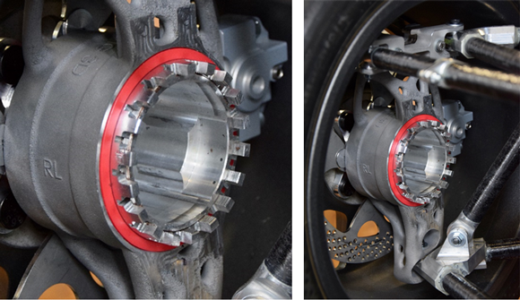
Under the collaboration, the chassis was improved with the addition of additively manufactured wheel carriers which were built on Eplus3D’s EP-M250Pro AM machine. Resulting in a weight saving of over 50%, the wheel carriers were reported to provide a significant increase in performance compared to the original CNC-milled component.
In racing, weight plays a key role in performance and driving behaviour of the vehicle. The wheel carrier is the central element for absorbing and transmitting forces, and designing for AM opened new possibilities for shape thanks to the design freedom it offers. Tools such as topology optimisation by finite element method (FEM) were used, where the software analyses the predominant loads of the component and calculates an optimised component geometry. This data is incorporated into the design process allowing different manufacturing processes to be compared and to avoid costly part changes.
In order to calculate the total forces which are applied to the component, the different predominant load cases were determined. For this purpose, all existing vehicle data were taken into account and evaluated with the help of numerical calculation software.
The following load cases were analysed:
- Maximum vertical impact
- Extreme braking with pitch compensation
- Extreme approach with pitch compensation
- Extreme cornering (dynamic calculation)
- Inside cornering wheel
- Outer cornering wheel
- Braking in pothole
- Braking in reverse
- Impact of track boundaries
- Deflection into the limit stop.
All vehicle data such as aerodynamic downforce, tyre operating field, kinematic pitch compensation, etc., were included in the calculation of real conditions. The aspired operating state is grip with a slight slippage, as this allows the maximum transmission of longitudinal and transverse forces.
Topology optimisation
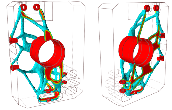
A working space model was created considering all geometric and kinematic boundary conditions. Important features were installation surfaces, fittings as well as functional clearances of the chassis kinematics. In order to not restrict the optimisation algorithm in advance, all possible freedoms were used. The geometry was divided into design areas (red) and non-design areas (grey). The design areas are mainly limited by peripheral components. Non-design areas are mostly bearing or connection points.
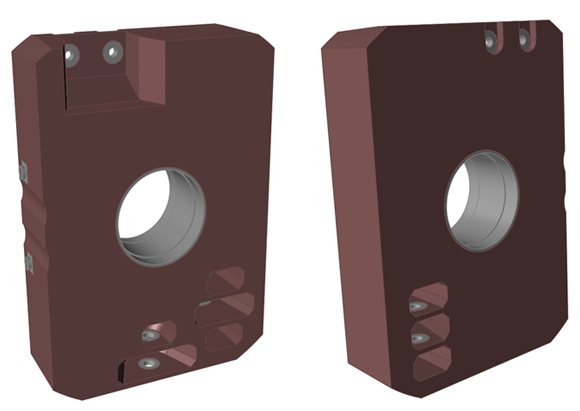
This split allows a finer meshing of the geometry regarding certain forces, resulting in a faster and more accurate simulation result. A high-strength and corrosion-resistant aluminium alloy AlSi10Mg was used that has a good strength-weight ratio.
The model was then meshed by finite elements. Tetrahedron elements with a second-order attachment function were used and the load cases with the previously calculated forces were applied. By using so-called ‘RBE-3 elements’, the force introduction point can be chosen to be the connection between wheel and street. These elements connect several independent nodes to a dependent node via a rigid binding and thus pair their degrees of freedom. This does not stiffen the geometry unnecessarily. Furthermore, the contact zone of the screwed-on fixtures is defined which results in a repeatable setting of the zone of the lintel adjustment.
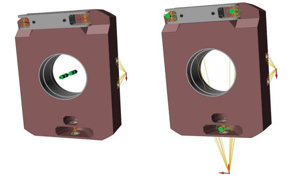
In the image above, two different considerations are examined: applying forces through the landing gear nodes (left); applying forces through the connection point of wheel and street on the bearing surfaces (right). The aim of topology optimisation is to achieve the medium yield with a more definite mass reduction. The software will ultimately be given the level of filling restriction, which describes the ratio of the output mass and target mass in the design volume.
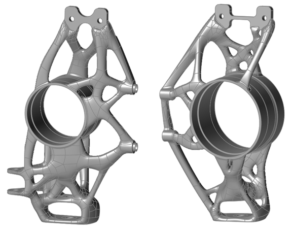
The mean yield was formed from a total of eighteen load cases and their respective importance as well as a safety factor. With the help of Altair’s OptiStruct, the optimal solution was calculated and further refined over several iterations. The created structures were then re-modelled by the designer. For this purpose, polygon meshes were generated around the proposed geometry which is freely customisable afterwards.
The new design was examined for its strength with stress analyses of all load cases. In order to obtain a better overview of all load cases, the result of overlapped stress results was considered, which overlays all maximum values of the load cases. When evaluating the simulation results, it was noticeable that elevated stresses occurred in hardly any area which was said to be due to the topology optimisation and safety factor used.
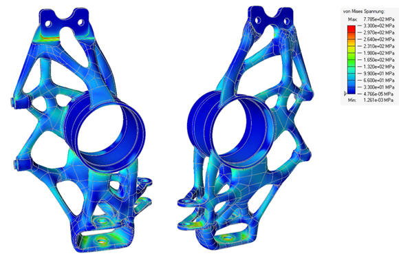
In the area of the lower chassis connection of the rear axle and in the contact area of the bracket of the front axle, singularities occurred in isolated load cases. This resulted in a few elements on sharp edges with increased tension. However, to obtain a meaningful result, the surrounding stresses were considered at a sufficient distance from the singularities. In a closer look, the Von Mieses comparative stresses of each load case were below the material yield limit.
Design for manufacturing
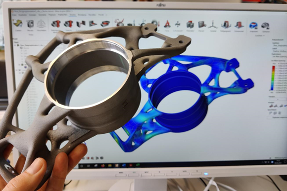
In order to ensure smooth production of the components, several optimisations were carried out to ensure the manufacturability of the topology-optimised component. These were developed by an Eplus3D consulting team together with participants of the Delta Racing e.V., and the machining specialist Klaeger Präzision GmbH & Co. KG. A rapid prototype was additively manufactured in PLA using the Fused Filament Fabrication (FFF) process for the consideration of all stakeholders.
The final parts were additively manufactured on Eplus3D’s EP-M250Pro Laser Beam Powder Bed Fusion (PBF-LB) AM machine. The parts were then annealed in a vacuum furnace to reduce part stress and with the help of a wire eroding machine, was separated from the build platform and the support structures removed. This was followed by sandblasting the surface as well as the machining of functional areas on a 5-axis CNC milling machine before quality control was carried out.

It was important for intrinsic stresses generated through the AM to be eliminated by stress annealing of the components. In order to keep the deformation through such residual stresses as low as possible from the beginning, the angles of the rods connecting the functional surfaces were lowered. After re-verification by the simulation tool, the changes could then be applied to the design.
The rod-like construction of the component and the few possible clamping surfaces favour vibrations during the machining post-processing, which lead to chatter marks. These changes make it possible to manufacture the entire component in one clamping process on a 5-axis CNC milling machine and thus to comply with all required shape and position tolerances.
The end result
The topologically optimised AM wheel carriers represent a further milestone in Delta Racing’s car development. In the pre-season, CNC milled wheel carriers were installed. With the bionic design, the potential of lightweight construction could be exploited, and the weight of the previous year’s wheel carrier reduced by 50%.
The new wheel carriers, therefore, weigh about 550 g per piece. All masses around the wheel belong to the unsprung masses, which act directly on the vehicle and are not delayed by the springs and dampers. Unsprung masses thus have a factor of 7 to the total moving mass. The drastic reduction of the unsprung masses makes the driving behaviour significantly more agile.