

PRIMES releases ScanFieldMonitor 2D for AM laser calibration

Laser beam diagnostic company PRIMES, headquartered in Pfungstadt, Germany, has released the ScanFieldMonitor 2D (SFM 2D), developed to meet the requirements of laser-scanner applications in remote welding and Additive Manufacturing machines.

The SFM 2D is the latest version of the company’s ScanFieldMonitor, first launched in 2018, with the updated system now enabling laser beam characterisation of the entire scan field to be completed within seconds. The device uses a novel measurement principle based on detecting the scattered laser light on a structured glass plate.
Development of the ScanFieldMonitor technology
Laser scanners can play a vital role in metal Additive Manufacturing, where both precision and speed are essential. The scanners’ performance depends on precise and accurate calibration to correctly direct the focus. The current standard for calibrating laser scanners involves measuring patterns inscribed on anodised aluminium plates using high-precision coordinate measuring machines.
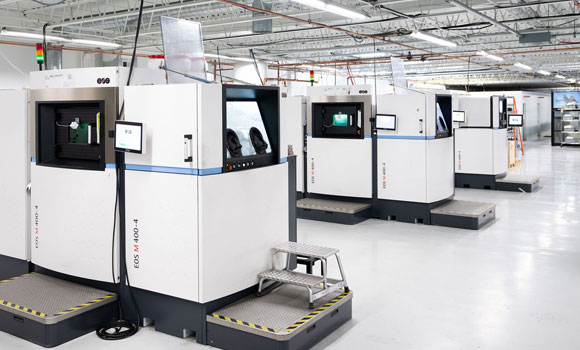
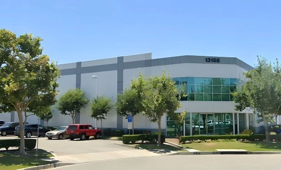
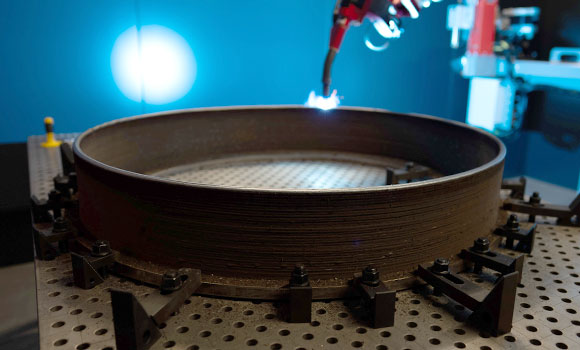
Article: Inside Nikon’s metal AM strategy
Part 2: Scaling industrial production in Long Beach
| Read now |
This process can be time-consuming, labour-intensive, and susceptible to errors due to the need for transporting and storing large and heavy plates. Additionally, the marking process employs very different laser parameters than the desired process – in particular, much lower laser power. Therefore, thermal focus shift of the optics and other laser-power induced effects are not considered. These issues can make calibration a major challenge for scanner manufacturers and users, which could lead to its omission.
Even when done, inaccurate calibration can lead to defects, compromised mechanical properties, and even complete failure of the manufactured parts. Factors such as temperature fluctuations, wear and tear, or contaminated optics can alter the calibration over time, necessitating regular verification. Scanners should therefore be recalibrated regularly, or at least undergo frequent calibration checks.

To meet these requirements, PRIMES developed the ScanFieldMonitor SFM 2D. It employs ultrashort pulse laser-engraved scattering structures in a transparent glass substrate. These structures enable the measurement of the moving laser beam across the entire scan field under process laser parameters. When the laser beam traverses the structured glass, the engraved features scatter the incident light, producing a characteristic signal detected by photodiodes.
Analysing the time-dependent scattering signal enables for a real-time calculation of all relevant geometrical and laser-related parameters of the scanner system, including position, velocity, direction, and beam diameter at the position of the scattering structure.
The SFM 2D’s glass plate measures 245 mm x 245 mm, and contains 225 individual 5 x 5 mm scattering structures. They are distributed such that they extend to within 10 mm of the edge of the machining area, where the largest errors typically occur. When the position of the laser beam is measured at all of these positions, a comparison of the target position and the actual position delivers a calibration dataset for the scanner. Such a calibration measurement over an entire scan field takes typically 20 seconds.
After the measurement, the result is immediately available. With the option of machine integration, the calibration data is calculated in-situ and can be transferred directly to the scanner.
Demonstrating the SFM 2D
To showcase the new SFM 2D, PRIMES performed measurements with a scanner at a focal length of 450 mm, leading to a scan field of 200 mm x 200 mm. The company used a laser at 1070 nm with a raw beam diameter of 15 mm and a power 750 W.
The calibration measurement was performed in the focal plane, where the beam shows a d4σ diameter of 86 µm. Initially, the company used a very rough scanner calibration, sufficient to ensure that the beam hit all measuring structures of the SFM 2D, but is not optimised for the current application.
At each of the measuring positions, the company averaged over ten vectors in the x and y directions. After the full scan field measurement, it calculated the difference between the target positions and the measured positions, finding correction values between 55 µm and 2.2 mm. This calibration dataset was then transferred to the scanner, where a full scan field measurement was repeated as a verification.
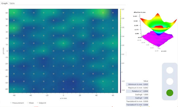
PRIMES found a maximum deviation of the position of 23 µm at the very edge of the scanfield and a mean deviation of 18 µm. This mean deviation only represents 20% of the beam diameter and therefore has negligible influence on the process results.
For the next step, a plane field correction can be performed by utilising the machine’s z-axis. This involves conducting a full caustic measurement at any position within the scan field. Therefore, measurements are conducted at multiple z-planes surrounding the focal position of the laser beam, with the beam diameters determined at each plane. Due to the 10 µm-wide measurement structures, small beams with diameters down to 50 µm are said to be suitable for characterisation.
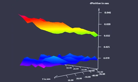
By performing individual curve fits to the caustic measurements, an accurate focal position can be determined for each location in the scan field. Based on these data, a plane field correction is applied to compensate for deviations in the z-position from the target position. This correction enables the laser focus to align precisely with the workpiece surface, regardless of deflections caused by beam steering. When measurements are performed at process power, including thermal focus shifts, the results are directly applicable to the actual production environment, facilitating accurate transfer of calibration data.
In the company’s example measurement, it obtained an inclination of the focal plane of 5.2 mrad. This inclination is due to the fact that in our laboratory the optical table on which the SFM 2D stands and the scanner platform are floating and have no rigid connection to each other. However, this misalignment can be compensated for by means of an appropriate calibration. The inclination was calibrated prior to measurement. The full measurement at eleven different z-levels was said to have taken fewer than four minutes.
Multi-laser machine calibration
Many modern Laser Beam Powder Bed Fusion (PBF-LB) Additive Manufacturing machines feature at least four individual scanner units to enable higher processing speeds. This configuration often results in multiple scanner units working simultaneously on a single large component.
To ensure the dimensional accuracy of the component, the overlap and alignment of the scanners are of critical importance. Specifically, all scanners must converge at the same point on the processing plane, both in the horizontal (x-y) plane and vertically along the z-axis. This condition must be satisfied across the entire scan field.
The measurement principle of the SFM 2D enables the precise assessment of these parameters, with each scanner unit directing its laser beam at the same measurement point on the SFM 2D. By performing a relative comparison of the spatial deviations among the scanner units, the lasers can be well aligned.